901.13 Lighting Proposed by Other Political Subdivisions on State Highways

This lighting policy, which was approved and adopted by the Missouri Highway and Transportation Commission, has been revised to set forth the guidelines governing lighting projects proposed by other political subdivisions for installation on state maintained highways.
All roadway lighting proposals and "Dusk-to-Dawn" lighting proposals within the scope of this policy may be approved by the district office. Special cases that are not covered by this policy shall be submitted to Traffic for approval. Policy guidelines are as follows.
1) Lighting Permits. Permits for lighting will be granted only to a political subdivision, which includes public utilities. The installation, operation and maintenance of highway lighting projects proposed by other political subdivisions shall be at the expense of the political subdivision.
When any lighting installation or system ceases to be maintained or operated for a period of 30 calendar days, notice shall be given in writing to the political subdivision to whom the permit for installation was issued. The notice will advise the political subdivision that if the lighting is not restored or work begun to restore in 15 calendar days from the date on the notice, such lighting will be considered a hazard and subject to removal by state forces with all materials and equipment removed becoming the property of the department for disposal or other use as deemed appropriate.
2) Continuous Versus Intersection Lighting. Roadway lighting proposals shall abide by the criteria described herein for either the continuous or intersection classification.
Typically, intersection lighting is utilized at isolated intersections and is allowable where a proposed intersection installation is at least 500 ft. from an existing lighting installation or cross-street intersection.
Continuous lighting shall be provided when the proposal includes the lighting of two or more intersections less than 500 ft. apart, typically in urban or suburban areas. Where an intersection is not involved, continuous lighting can be considered if the length of roadway to be lighted is at least 500 ft.
For proposals involving diamond interchanges or at-grade intersections on divided highways, it is not permissible to light only one ramp terminus or outer road intersection. If it is desirable to light the intersection of outer road and cross-street, lighting at both ramp terminals (diamond interchange) or at-grade intersection is first required.
901.13.1 Required Illumination and Uniformity Ratio
901.13.1.1 Maintenance Factor. When computing average maintained intensity for continuous or intersection lighting, use a maintenance factor of 0.7 for all mounting heights.
901.13.1.2 Continuous Lighting.
901.13.1.2.1 Average Maintained Intensity. Continuous lighting installations along freeways, urban arterials, expressways and ramp connections thereto shall provide an average maintained intensity of not less than 0.6 footcandle and a minimum intensity of not less than 0.2 footcandle. Continuous lighting installations on existing roadways, not including freeways, urban arterials, expressways or ramp connections thereto, must provide an average maintained intensity of not less than 0.4 footcandle and a minimum intensity of not less than 0.2 footcandle.
901.13.1.2.2 Uniformity Ratio. The uniformity ratio is the ratio of average footcandles of illuminance on the pavement area to the footcandles at the point of minimum illuminance on the pavement. Continuous lighting must provide a uniformity ratio of 4:1 or better for 45-ft. mounting heights and 6:1 or better for 30-ft. mounting heights.
When ornamental lighting is proposed, the veiling luminance ratio of 0.3:1 is required. This is the maximum ratio of veiling luminance to average pavement luminance.
901.13.1.2.3 Intersection Lighting. Luminaires at intersections shall be located to furnish silhouette discernment lighting unless raised islands or medians are present at which time direct reflectance illumination shall be used. Basic lighting at intersections and interchanges must provide an average maintained intensity of not less than 0.6 footcandle.
901.13.2 Lamp Rating
The following establishes the minimum acceptable initial lamp rating by roadway classification.

901.13.2.1 Expressway and Freeway Lighting and Continuous, Basic Interchange, Ramps and Cross Street Lighting. Lamps shall have an initial rating of 9,500 lumens or greater for 30-ft. mounting height. Lamps shall have an initial rating of 21,000 lumens or greater for 45-ft. mounting heights. Refer to Lamp Data, Figure 901.13.4, for possible lamp wattages and mounting heights to meet this criteria.
901.13.2.2 All Other Highways for Continuous or Intersection Lighting. Lamps shall have an initial rating of 7,950 lumens or greater for 30-ft. mounting heights. Lamps shall have an initial rating of 21,000 lumens or greater for 45-ft. mounting heights. See Lamp Data, Figure 901.13.4, for possible lamp wattages and mounting heights to meet this criteria.
901.13.3 Horizontal Location of Luminaires
Luminaires are to be positioned within 3 ft. at the 30-ft. mounting height and 5 ft. at the 45-ft. mounting height from the edge of the nearest traffic lane. This applies to either continuous or intersection lighting.
901.13.4 Lighting Style, Luminaire Type and Mounting Height
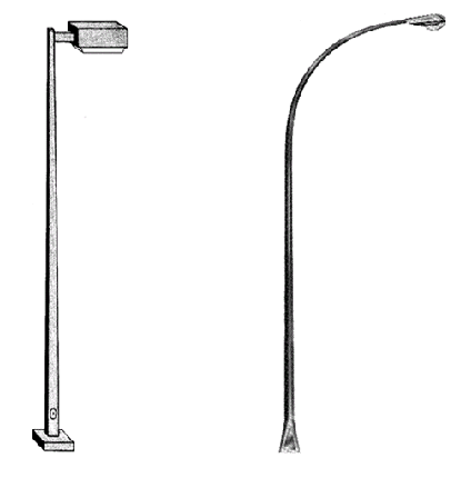
901.13.4.1 Roadway Luminaires. The “cobrahead” or “horizontal” luminaire designs are recommended for all highway lighting installations. Lamp data, recommended luminaire type and mounting heights for these types of luminaires can be found in Lamp Data, Figure 901.13.4.
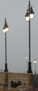
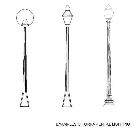
901.13.4.2 Ornamental Lighting. Ornamental lighting requests are very popular in historic areas. However, there are few manufacturers that actually make ornamental fixtures for roadway lighting. When the intent of ornamental lighting fixtures is to light the roadway, they must meet the illumination and uniformity ratio as well as the veiling luminance criteria established in 901.13.1. Computer calculations must be submitted with the proposal. If they do not meet this criteria, these fixtures may be allowed for lighting of sidewalks and pedestrian areas only.

901.13.4.3 Architectural Street Lighting. Architectural street lighting may be allowed if the design conforms to the required illumination and uniformity ratio for continuous lighting as established in EPG 901.13.1. Computer calculations must be submitted with the proposal.

901.13.5 Pole Location
Lighting poles shall be located at the least hazardous location with respect to traffic and the least obstructive for maintenance operations. The American Association of State Highway and Transportation Officials (AASHTO) clear zone guidelines from the Roadside Design Guide are used to determine the desired distance for pole installation. Clear zone information is available.
When determining the required clear distance, first check whether a clear zone has been previously established for the route by Design. If a clear zone has not already been established then the higher of either the posted or 85th percentile speed is the determining factor. This will provide the greatest margin of safety.
If poles cannot be placed at or outside of the clear zone distance, the pole may be placed within the clear zone if the poles have the appropriate breakaway device. However, the minimum distance a pole can be placed is 2 ft. behind the face of the curb or shoulder point.
Wood poles or poles without the breakaway feature are acceptable only when located beyond the distance required by the clear zone guidelines or where several other non-breakaway obstacles are located in the vicinity of the proposed installation. In the latter case, it is recommended to send all proposals and district recommendations to the division office for approval.
Poles may be located behind existing guardrail if protected from all directions of travel. If located behind guardrail, poles shall be offset sufficiently to allow for deflection of the guardrail under impact, see MoDOT Standard Drawing 606.00 for offsets.
If proposals are sent to the division office for review, all locations shall be field checked by district personnel and photographs and plans of the proposed location shall be submitted.
901.13.6 Safety Bases and Material Composition of Poles
Proposed lighting projects must utilize steel or aluminum poles with acceptable safety bases when within the clear zone. Safety bases shall be certified as meeting the breakaway criteria and structural requirements as set forth by the current AASHTO specifications. The applicant may use fiberglass poles provided that the manufacturer certifies the poles meet AASHTO criteria for breakaway features. This certification must be included in the submittal. A fused slip connector assembly shall be required wherever safety bases are required. Refer to MoDOT Standard Drawing 901.02.
A proposed extension or addition to a lighting facility previously installed by the state should utilize material similar to the existing lighting poles.
901.13.7 Wiring
Where breakaway bases are required, overhead wiring will not be permitted. In cases where wood poles or poles without the breakaway feature are permissible, overhead wiring will be permitted. Where overhead wiring is permitted, cable crossings will not be permitted from pole to pole on a staggered pole arrangement. Only normal cable crossings will be permitted to complete circuit wiring.
901.13.8 Typical Designs for Intersection Lighting
Refer to 901.1 for typical design of intersection lighting.
901.13.9 Typical Designs for Continuous Lighting
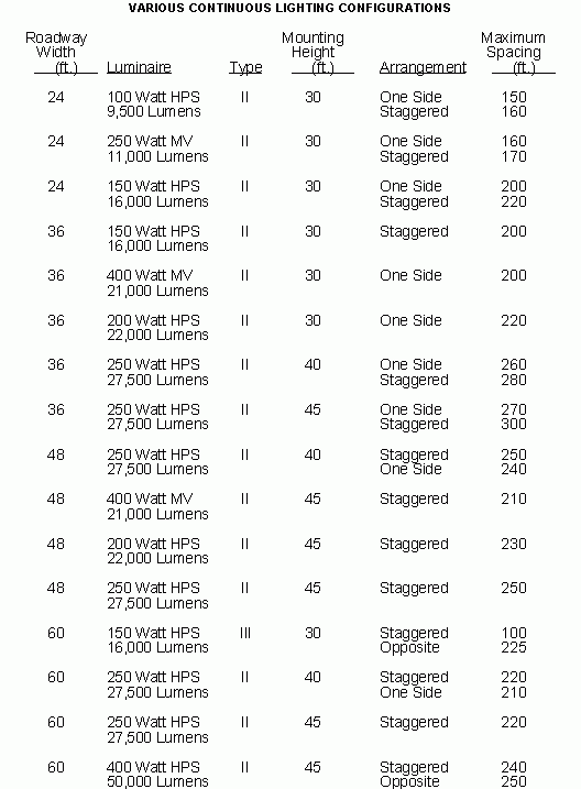
The tables below and in figures in 901.11.1.1 list typical continuous lighting designs for different roadway width, luminaire and mounting height combinations. Various brands of luminaires perform slightly different; therefore, these tables are to be used as a guide.
If proposals differ from the examples, computer calculations shall be submitted to justify luminaire, type, mounting height and/or spacing.

901.13.10 Submittal
Applicants must provide two complete sets of plans to the district office. Plans must be drawn to scale showing proposed lighting installation(s), width of pavement and shoulders, right of way limits, traffic islands, guardrail, power poles and other non-movable obstacles. The applicant is also to fill out Part A of the Permit Request Form for Highway Lighting, Figure 901.13.10.
The district must conduct an on-site investigation of the proposed installation to verify applicant's plans and completed Part B of the “Permit Request Form For Highway Lighting”. If the proposal meets the policy outlined in this article, the district may approve the request and a permit may be issued for the installation. All plans, photos and permit request forms shall be filed with the permit.