751.39 Pile Footings
751.39.1 Dimensions
Long, narrow footings (length to width ratio ≥ 2.0) supporting individual columns are not desirable, and care should be taken to avoid their use unless space constraints or eccentric loading dictate otherwise.
 |
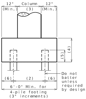 |
| (1) | Min. = 1/8 x (Distance from top of beam to bottom of footing.) | |||||||||||||
| (2) | 3'-0" (Min.) & 6'-0" (Max.) for steel HP piles, 14" CIP piles. 3D (Min.) and 6D (Max.) for 16”, 20" and 24" CIP piles. (D = pile diameter) | |||||||||||||
| (3) | Indicates column diameter, or column length or width on a hammer head pier. | |||||||||||||
| (4) |
| |||||||||||||
| Note: For column diameters 4'-0" and greater use a 4'-0" min. footing thickness. If SDC A SD1 ≥ 0.1, provide seismic details similar to SDC B. | ||||||||||||||
| (5) | 12" for seismic design category A and 18" for SDC B, C, & D. If SDC A SD1 ≥ 0.1, provide seismic details similar to SDC B. | |||||||||||||
| (6) | Use 18" for steel HP piles and 14" and 16” CIP piles. The distance from the side of any pile to the nearest edge of the pile cap shall not be less than 9 inches. |
 |
STAGGERED PILE (7 Pile Footings shall not be used.) |
* The maximum pile spacing is 4'-0".
** 3'-0" (Min.) & 6'-0" (Max.) for steel HP piles, 14" CIP piles. 3D (Min.) and 6D (Max.) for 16”, 20" and 24" CIP piles. (D = pile diameter)
751.39.2 Limit States
The following limit states shall be considered for pile footing design:
- STRENGTH – I
- STRENGTH – III
- STRENGTH – IV
- STRENGTH – V
- SERVICE – I
- EXTREME EVENT – II
See LRFD Table 3.4.1-1 and LRFD 3.4.2 for Loads and Load Factors applied at each given limit state.
751.39.3 Pile Design
General
Design the number, size and spacing of piles based on the guidance provided in EPG 751.36 .5.1 Design Procedure Outline, EPG 751.36.5.8 Additional Provisions for Pile Footings and the guidance provided herein.
For friction piles situated in soft cohesive soils or in cohesionless soils underlain by a soft cohesive layer, the pile group shall be checked for block failure in accordance with LRFD 10.7.3.9. Soft cohesive soils are defined as soils with average undrained shear strength less than 1 ksf. For additional guidance refer to FHWA GEC 012: Design and Construction of Driven Pile Foundations - Volume 1, Section 7.2.2.3.
The pile group shall be checked for horizontal loads in accordance with LRFD 10.7.2.4. Soil-structure interaction shall be considered for full depth of pile. The lateral load shall be checked with the minimum and maximum pile axial loads determined from the procedure outlined in EPG 751.36.5.8 Additional Provisions for Pile Footings for the Strength-III, Strength-V and Extreme Event-II limit states. A step by step design procedure for laterally loaded pile groups using lateral single pile analysis is presented in FHWA GEC 012: Design and Construction of Driven Pile Foundations - Volume 1, Section 7.3.7.6.
751.39.4 Concrete Footing Design
Shear Line
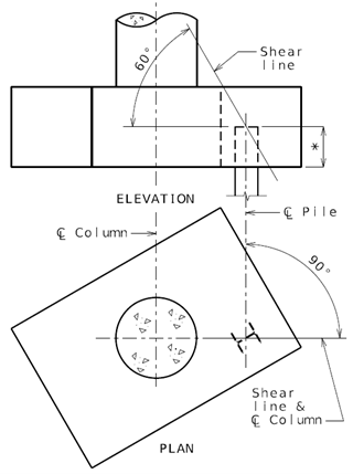
If the shear line is within the column projected, the footing may be considered satisfactory for all conditions and standard #6 hairpin bars shall be used.
If the shear line is outside of the column projected, the footing must be analyzed and reinforced for flexure and checked for shear.
Footing depths may be increased, in lieu of reinforcement, if an increase would be more economical. (6'-0" Maximum depth, with 3" increments.)
* 12 inches or 18 inches (see EPG 751.39.1 Dimensions)
Flexure
The critical section for flexure shall be taken at the face of the columns (concentric square of equivalent area for round columns).
The factored moment shall be taken as the sum of the factored pile reactions multiplied by their respective distance from the critical section. Only piles located outside the critical section should be considered.
The reinforcement shall be as indicated in EPG 751.39.5 Reinforcement, except that the standard #6 hairpin bars may be used for small footings if they provide sufficient steel area.
Distribution of Reinforcement
Reinforcement in Bottom of Footing
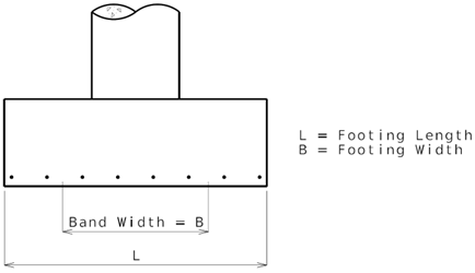
Reinforcement shall be distributed uniformly across the entire width of footing in the long direction. In the short direction, the portion of the total reinforcement given by LRFD Equation 5.12.8.5-1 shall be distributed uniformly over a band width equal to the length of the short side of the footing, .
the ratio of footing length (long side) to width (short side) = L/B
- area of steel in the band width (in.2)
- total area of steel in short direction (in.2)
The remainder of the reinforcement required in the short direction shall be distributed uniformly outside the center band width of footing.
Reinforcement in Top of Footing
Reinforcement in the top of the footing shall be provided based on a seismic analysis for Seismic Design Categories B, C and D or where seismic details are required. This reinforcement shall be at least the equivalent area as the bottom steel in both directions. The top steel shall be placed uniformly outside the column reinforcement.
Shear
(LRFD 5.7.3 or 5.12.8.6)
The shear capacity of footing in the vicinity of concentrated loads shall be governed by the more severe of the following two conditions. For excessive shear, increase footing depth.
One Way Shear
Critical Section at distance from face of column.
- factored shear resistance
- nominal shear resistance
- 0.9
- nominal shear resistance of the concrete (kip)
- factor indicating the ability of diagonally cracked concrete to transmit tension and shear.
- 2.0
- effective shear depth (in.)
- width of footing (in.)
- design concrete compressive strength (ksi)
sum of factored pile reactions located outside the critical section (kip)
Two Way Shear
Critical Section at distance from face of column.
- the perimeter of the critical section for shear (in.)
- effective shear depth (in.)
- design concrete compressive strength (ksi)
sum of factored pile reactions located outside the critical section (kip)
Notes: 1) f’c for footing is typically 3.0 ksi and matches f’c of column. Column and footing f’c may be increased to 4.0 ksi with approval from SPM or SLE.
- 2) For simplicity, when calculating , the maximum pile reaction may be assumed to act on all piles located outside the critical section.

|

|
(1) Piles to be considered for shear. Center of piles are at or outside the critical section.
751.39.5 Reinforcement
Unreinforced Footing - Use only in Seismic Design Category A
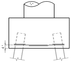
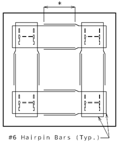
The term “unreinforced footing” is used for footings where only #6 hairpin bars are required.
Do not use unreinforced footing if SDC A, SD1 ≥ 0.1.
Unreinforced footings shall only be used when the shear line for all piles is within the column projected, or where additional flexural steel is not required by design (not typical).
 |
 |
(4 Pile Footing) |
(4 Pile Footing) |
* See EPG 751.5.9.2.8.2.
Notes: Use Class B lap splice of deformed bars in tension.
- Use for all types of piling.
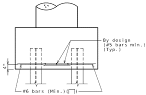
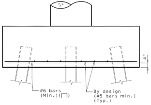
Reinforced Footing - Seismic Design Category (SDC) A
If SDC A, SD1 ≥ 0.1, provide seismic details similar to SDC B.
 |
 |
 | |
* See EPG 751.5.9.2.8.2
Notes: Use Class B lap splice of deformed bars in tension.
- The minimum bar size for flexural steel that meets all design requirements is preferred. Straight bars are preferred to hooked ends.
Reinforced Footing - Seismic Design Categories B, C & D
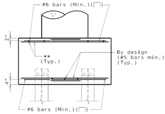 |
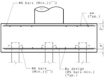 |
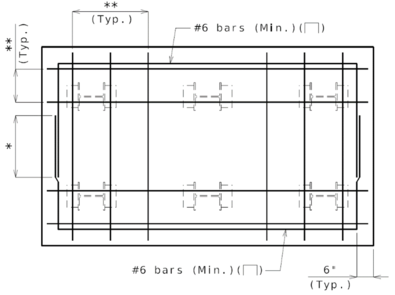 |
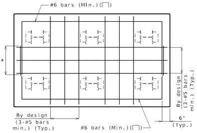 |
For anchorage of piles for seismic details for SDC B, C and D, see EPG 751.36.4 Anchorage of Piles for Seismic Details.
* For reinforcement in top of the footing and bottom of footing, See EPG 751.5.9.2.8.2 for lap splice.
- Note: Use Class B lap splice of deformed bars in tension.
**Place the top reinforcement uniformly outside the column reinforcement. Use same area of steel in the top of the footing as is required for the bottom.
Notes: When complete seismic analysis is required per bridge seismic design flowchart, Joint shear reinforcement shall be provided in accordance with AASHTO Guide Specifications for LRFD Seismic Bridge Design (SGS) 6.4.5.Unreinforced footings shall not be used in seismic performance categories B, C & D.
751.39.6 Seal Course
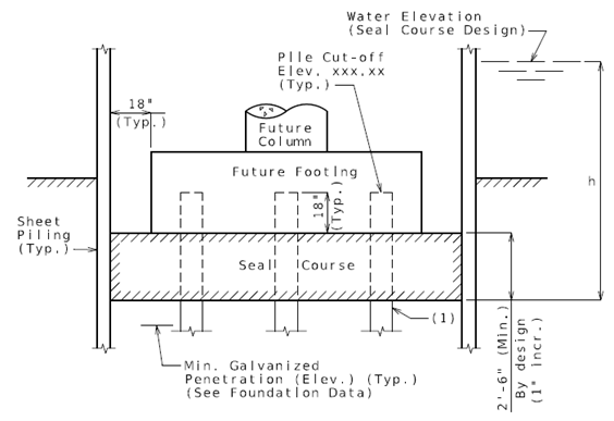
|
(1) All pile shall be vertical. |
751.39.6.1 General Requirements
Water elevation is to be determined for the site conditions by the preliminary design section; generally, less than the average of high and low water.
Determine the factored uplift load per pile by deducting the weight of the seal course and friction between seal course and sheet piling of cofferdam from the uplift force produced by the hydrostatic head "h".
Use a friction value between the seal course and the sheet piling of 2 lbs./in2 acting on (perimeter x depth) of seal course.
Factored uplift load per pile =
- Load factor for uplift x (Uplift force of water – Weight of seal course – Friction between seal course & sheet piling) / No. of piles
751.39.6.2 Pile Pull-out Force
Maximum factored resistance per pile shall be determined by the minimum of:
- (1) Factored resistance for skin friction = Geotechnical resistance factor for skin friction x Nominal skin friction resistance
- Calculate nominal skin friction resistance of pile (without tip resistance).
- Geotechnical resistance factor for skin friction, φup. from LRFD Table 10.5.5.2.3-1
- Use φup = 0.2 from LRFD table 10.5.5.2.3.-1 for single pile unless higher resistance factor can be justified based on soil type and test method.
- (2) Factored resistance for pile tension = Structural resistance factor for pile tension x Yield strength of steel x Steel area of pile.
- Note: Since CIP pile is not filled at this stage, use steel pipe pile area without concrete to determine the factored resistance for pile tension. ASTM 252 allows “the wall thickness at any point shall not be more than 12.5% under the specified nominal wall thickness. For steel pipe pile area computation consider 87.5% of wall thickness.
- Structural resistance factor for pile tension, φy = 0.25
- (3) Factored resistance for 10 psi adhesion = structural resistance factor for 10 psi adhesion x 10 psi x Pile perimeter x Depth of seal course
- Structural resistance for 10 psi pile adhesion, Φ3 = 1.0
- For HP pile perimeter use 2*(Depth + Width) of HP shape.
Plan Reporting
Seal Course size shall be shown on the plans as designed.
Seal Courses are typically designed for one footing only. They may be designed for uplift loads developed under more than one footing or where there is economy of scale in constructing a larger cofferdam, for example:
- (1) where individual seal courses are proximate and costlier than considering one large seal course under more than one footing, and
- (2) where removal of an existing footing requires a larger cofferdam to be constructed enclosing both existing and new locations of footings with the result that a larger than usual seal course size may be less costlier than individually constructed cofferdams.
Where a seal course is to be designed to resist the uplift loads resulting from the proposed construction of more than one footing, the plans should show or indicate that more than one footing was considered in designing the seal course and the pay item adjusted accordingly.
Seal Course size shown on plans should not be allowed to be resized as in combining adjacent seal course(s) or lessening thickness without approval from either the Structural Project Manager or Structural Liaison Engineer and an official change order request from district Construction and Materials Division.
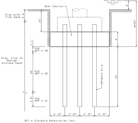
751.39.6.3 Example: LRFD Seal Course Design
Check if Seal Course design is adequate.
Given
- Concrete Strength f'c= 3000 psi
- Pile spacing = 3'-0"
- 12 - HP 10 x 42 piles
- Area of an individual HP 10 x 42 Pile = A = 12.4 in2
- Depth of HP shape = 9.7 inch
- Width of HP shape = 10.1 inch
- Yield strength of steel Fy = 36 ksi
- Maximum axial load Py = Fy (A) = 36 ksi (12.4 in2) = 446.4 kips
- Hydrostatic head h = 19'
- Seal Course = 12' x 15' x 3'
- Pile embedment below seal course = 15'
Solution
Factored uplift load per pile:
| Uplift force of water | = 12'(15')(19')(0.0624 kips/ft3) = 214 kips |
| Weight of seal course | = 12'(15')(3')(0.15 kips/ft3) = -81 kips |
| Friction of sheet pile | = (15'+12')(2)(3')(144)(0.002kips/in2) = -47 kips |
| Net uplift of piles | = 86 kips |
| Factored uplift load per pile | = 86 kips/12 piles = 7.17 kips/pile |
Maximum factored resistance:
Use the minimum of:
- (1) Factored resistance for skin friction = Geotechnical resistance factor for skin friction x Nominal skin friction resistance:
- Nominal skin friction resistance of pile is 53.97 kips.
- Geotechnical resistance factor for skin friction = 0.2 for uplift resistance of single pile from LRFD 10.5.5.2.3-1 (Conservatively assumed 0.2),
- Factored resistance for skin friction = 0.2 x 53.97 kips = 10.79 kips
- (2) Factored resistance for pile tension
- = 0.25 x Fy x Steel area of pile
- = 0.25 x 36 x 12.4
- = 111.6 kips
- (3) Factored resistance for 10 psi adhesion = Structural resistance factor for 10 psi pile adhesion x 10 psi x Pile perimeter x Depth of seal course
- Structural resistance for 10 psi pile adhesion, Φ3 = 1.0
- = 1.0 x 10/1000*2 x (9.7+10.1) x 3 x 12
- = 14.26 kips
Minimum from (1), (2) & (3):
Maximum factored resistance = 10.79 kips
Factored uplift load per pile = 7.17 kips
7.17 kips ≤ 10.79 kips, O.K.
Try seal course depth = 2'-6"
Factored uplift load per pile :
| Uplift force of water | = 12'(15')(18.5')(0.0624 kips/ft3) = 207.8 kips |
| Weight of seal course | = 12'(15')(2.5')(0.15 kips/ft3) = -67.5 kips |
| Friction of sheet pile | = (15'+12')(2)(2.5')(144)(0.002 kips/in2) = -38.9 kips |
| Net uplift of piles | = 101.4 kips |
| Factored uplift load per pile | = 101.4 kips/12 piles = 8.45 kips/pile |
Maximum factored resistance:
Use the minimum of:
- (1) Factored resistance for skin friction
- = Geotechnical resistance factor for skin friction x Nominal skin friction resistance
- = 0.2 x 53.97 kips = 10.79 kips
- (2) Factored resistance for pile tension = 111.6 kips
- (3) Factored resistance for 10 psi pile adhesion = Structural resistance factor for 10 psi pile adhesion x 10 psi x Pile perimeter x Depth of seal course
- Structural resistance factor for 10 psi pile adhesion, Φ3 = 1.0
- = 1.0 x 10/1000*2 x (9.7+10.1) x 2.5 x 12
- = 10.88 kips
Minimum from (1), (2) & (3):
Maximum factored resistance = 10.79 kips
Factored uplift load per pile = 8.45 kips
8.45 kips ≤ 10.79 kips, O.K.
(Using a depth of 2'-6" is an economical design.)
