642.9 Sidewalk Ramp and Curb Ramp Design Criteria
| Additional Information |
| ADA Standards Section 4.8.5 |
| Sec 608 |
| Standard Plan 608.10 |
| Standard Plan 620.00 |
642.2.1 Slope and Rise of Sidewalk Ramps
When the running slope, or grade, of a sidewalk exceeds 5% it is a ramp. If the sidewalk is adjacent to the street or separated by a narrow planting strip, the sidewalk grade may be equal to the grade of the street and not be considered a ramp. Ramps typically occur on an accessible route leading to a facility or otherwise separated from the street.
The cross slope for all ramps is to be 1%, but a maximum of 2.0% is allowed by ADA standards. Although the maximum running slope of a ramp in new construction is 1V:12H (8.33%), as discussed before, all sidewalks are to be designed with the least running slope possible. In an alteration project if it is technically infeasible to meet the running slope requirement, every effort should be made to flatten the slope as much as possible and provide landings where necessary. Clear documentation of any exceptions should be kept in the project file.
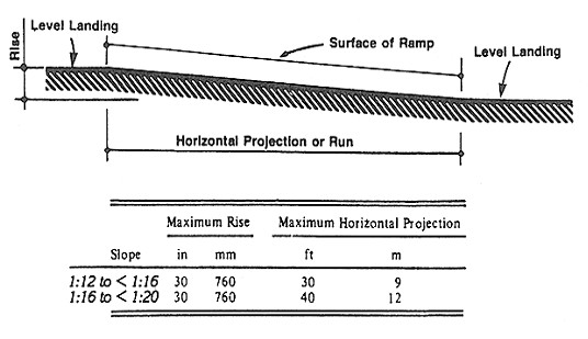
The maximum rise in any run will be 30 in. Examples of various slopes and ramp lengths are shown in Figure 642.2.1.


A landing will be located at the top and bottom of all ramps and between segments that have a 30 in. rise. The landing will be at least the width of the ramp with a minimum length of 60 in. If a turn is required the landing must be 5 ft. x 5 ft. For example, a segment with a running slope of 1V:12H, or 8.33% will require a 5 ft. x 5 ft. landing every 30 ft. if it is part of a switchback access route.
For shorter distances, exceptions are allowed in alteration projects when the allowable grade cannot be obtained:
- A slope between 1V:10H and 1V:12H (10% - 8.33%) is allowed for a maximum rise of 6 in.
- A slope between 1V:8H and 1V:10H (12.5% - 10%) is allowed for a maximum rise of 3 in.
- A slope steeper than 1V:8H (12.5%) is not allowed.
A vertical rise greater than 6 in. will require a handrail. Handrails must be compliant with ADA standards, Section 4.8.5 (http://www.ada.gov/reg3a.html#Anchor-19425)
Edge protection will be provided on ramps and landings with drop-offs and shall have curbs, walls, railings, or projecting surfaces that prevent people from slipping off the ramp. Curbs shall have a minimum height of 2 in.
642.2.2 Curb Ramps
Curb ramps will be provided wherever a sidewalk crosses a curb. Curb ramps should not be installed where there are no sidewalks as they may mislead a person with disabilities to an area where an accessible pedestrian pathway is not provided. However, if there is a committment to install sidewalks in the near future, approximately 1 year or less, curb ramps should be installed with a current project if it results in more efficient construction and lower cost. Curb ramps should be installed at each end of an accessible route to allow access onto the route.
The design and construction of curb ramps require thought and planning. The curb ramp must be designed to meet the existing topographical and physical constraints, and the requirements for curb ramp slope, cross slope, landings and connection to the street.
Curb and sidewalk ramps will be designed in accordance with the standard plans, or varied to fit the needs at a particular location. Situations that do not fit the standard plans are to be identified on a field check. If a particular curb ramp differs from the standard plans, the ramp will be detailed on the plans. The exact location of the curb ramps and crosswalks for intersections will be shown on the plans.
The following criteria apply to all curb ramp situations:
- Width - curb ramps in new construction will have a clear width of 5 ft., exclusive of flared sides. In an alteration, the width will be the same as the adjoining sidewalk or a minimum of 4 ft.
- Cross slope - The cross slope on all curb ramps will be a minimum of 1%, up to 2.0% maximum.
- Running slope - The least possible running slope will be used for all ramps. The minimum running slope for drainage purposes is 1%. In new construction, the maximum slope allowed by ADAAG is 8.33% (1V:12H). Consideration should be given to construction accuracy and future settlement. In an alteration project when the maximum slope cannot be met due to technical infeasibility, a steeper slope between 1V:10H and 1V:12 (10% and 8.33%) may be used for a maximum rise of 6 in., or a slope between 1V:8H and 1V:10H (10% and 12.5%) may be used for a maximum rise of 3 in. A slope greater than 12.5% is not allowed.
- Grade breaks - Grade breaks at the top and bottom of perpendicular curb ramps shall be perpendicular to the direction of ramp run. Grade breaks shall not be permitted on the surface of curb ramps, blended transitions and landings within the pedestrian access route. Surface slopes that meet at grade breaks shall be flush.
- Landings - Curb ramps: A minimum 5 ft. x 5 ft. level landing with a minimum of 1% and no more than 2.0% cross slope in any direction will be provided wherever two sidewalks cross, or a turn may be required. Perpedicular curb ramps may require a pedestrian to choose a direction from a landing at the top of the ramp. Parallel curb ramps require a landing at the bottom so that a pedestrian can turn to enter the streeet. A diagonal ramp requires a landing at the top and a 4 ft. x 4 ft. clear space at the bottom protected within the crosswalk markings.
- Detectable warnings, or truncated domes - Detectable warnings must be placed at all public streets and signalized intersections. They will be located at the bottom of each ramp a maximum of 5 ft from the curb face, or 6 to 8 in. from the curb face if the distance to the bottom of the ramp is greater than 5 ft. Additional information may be found in EPG 642.2.3 Detectable Warnings.
- Islands and medians - Raised islands and medians in crosswalks will be cut through level with the street and include a level passing space of 5 ft. x 5 ft. The cut through width will meet the requirement of an accessible route. Median cut through length is to be 4 ft.min. Detectable warning will be provided at each entrance to the street.
- Steps - Sidewalk ramps will be provided at locations where steps occur, such as at the ends of bridges having sidewalks across the bridge or at pedestrian grade separations.
- Obstacles - No obstacles (grates, utility covers, etc.) should be within a ramp. If they cannot be avoided, they will have stable, firm and slip resistant surfaces, have flush transitions, and meet the change in level requirements. Storm drain inlets are to be designed outside of the ramp area, but located so as to minimize water runoff or pooling of water at the bottom of ramps.
- Parking - Curb ramps will be located or protected to prevent their obstruction by parked vehicles.
- Crosswalk markings - Curb ramps at marked crosswalks will be wholly contained within the markings, excluding any flared sides. The minimum crosswalk is 6 ft.
- Pay items - The designer will estimate the square yardage for curb ramp and include it with the estimate for sidewalks and the quantity will be shown on the 2B sheet(s). A separate pay item is included for detectable warnings since they are not required on all ramps, and in many cases, are required to be retrofitted on existing curb ramps.
- See the Sec 608, Standard Plan 608.10 and EPG 642.1.4 for additional information.
642.2.2.1 Curb Ramp Alignment
 |
 |
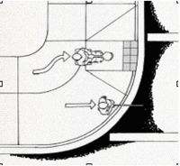
The accessible route should be perpendicular to the curb being crossed to provide a level cut for wheelchairs and directional cues for the visually impaired. By placing curb ramps perpendicular to the curb, grade changes are at right angles that will allow all four wheels of a wheelchair to be in contact with the ground at all times. Curb ramps located at the tangent point provide the shortest pedestrian crossing. Alignment of curb ramps, crosswalks and raised islands is an important consideration in providing a safe crossing for the visually impaired.
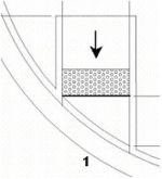
For large radii, it is often not possible to both place curb ramps perpendicular to the curb and in-line with the pedestrian crossing. Ramps may be set back from the curb to provide a grade break that is perpendicular to the ramp slope and a landing or blended transition will continue to the curb. If the bottom of the ramp is more than 5 ft. from the curb, detectable warnings are placed at the back of the curbline. Parallel ramps are often useful in this situation.
642.2.2.2 Flares on Ramps
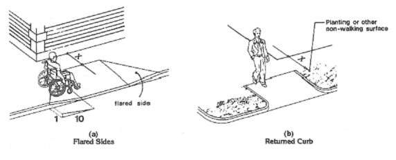
If a curb ramp is located where pedestrians may walk across the ramp, or the ramp is not protected by handrails, guardrails, or a permanent obstacle, and the landing or the sidewalk at the top of the ramp is 4 ft. or wider, the flared sides of the ramp will have a maximum slope of 1V:10H (10%). If, due to a technical infeasibility, the sidewalk is narrower than 4 ft., the maximum slope will be 1V:12H (8.33%). The sidewalk width, X in Figure 642.2.2.2, must be at least 3 ft. A parallel ramp may be more appropriate in some situations.
Vertical curbs or flares greater than 1V:10H are allowed where the pedestian path will not cross the ramp. Refer to Figure 642.2.2.2. Handrails are not required on curb ramps.

642.2.2.3 Gutters
The gutter slope is parallel to the ramp and perpendicular to the curb. Because the slopes of adjacent gutters and streets significantly affect the overall accessibility of curb ramps, the rate of change of grade between the gutter and the ramp imust not exceed 13% over a 2 ft. interval. The cross slope of the road or gutter surface immediately adjacent to the curb ramp must not exceed 5%.
The transition between the ramp and gutter is to be smooth and flush. For new construction, transitions from curb ramps to sidewalks, gutters or streets must be flush and free of abrupt changes. For existing locations where a smooth transition cannot be acheived, changes in level between ¼ in. and ½ in. must be beveled with a slope no greater than 1V:2H, and changes in level greater than ½ in. need to be removed or ramped. Maximum slopes adjoining a curb ramp must not exceed 1V:20H (5%).
It is improtant to ensure that water does not puddle at the curb opening. Where drainage crosses the opening and may enter the ramp, or landing area, a maximum 8.33% slope may begin at the face of the curb, resulting a ½ in. rise at the back of the curb in a 6 in. curb opening.
642.2.2.4 Landings
Landings at curb ramps allow people with mobility impairments to move completely off of the ramp and onto the sidewalk. They provide a level area for resting, turning, or reaching pedestrian signal buttons. The slope for all landings must be between a minimum of 1% for drainage and a maximum of 2.0% for pedestrian stability in all directions.
A minimum 5 ft. x 5 ft. landing must be provided wherever two sidewalks cross, or a turn may be required. Perpedicular curb ramps may require a pedestrian to choose a direction from a landing at the top of the ramp. Parallel curb ramps require a landing at the bottom so that a pedestrian can turn to enter the streeet. A diagonal ramp requires a landing at the top and a 4 ft. x 4 ft. clear space at the bottom protected within the crosswalk markings.
For retrofit projects, where geometric or right of way restrictions exist, the landing width may be reduced to 4 ft. MoDOT policy will be 5 ft. x 5 ft. to coincide with sidewalk widths and passing space. If landings are reduced below 4 ft., the reasons need to be documented. Please note that requirement for ramps differ from those of curb ramps in that ramps must have the same width as the approaching sidewalk and a minimum length of 5 ft.
642.2.2.5 Types of Curb Ramps and Design Applications
Curb ramps at intersections need to be designed on an individual basis. The location and type of the ramps are to be shown on the plans to ensure all details of the ramps have been taken into consideration and are constructable to MoDOT standards. Determining pedestrian pathways early in the design process is essential. The best ramp configuration for a given location may impact the location of utilities, traffic signals, light poles, storm drainage and other roadside features. It is recommended that the sidewalk and ramps be laid out early in the preliminary plans and in coordination with other roadside features.
There are a variety of curb ramp types. The pattern to be used depends on the location, type of street and existing design constraints. Curb ramps are normally categorized by their position relative to the curb line. The three most common configurations are perpendicular, parallel and diagonal. See EPG 642.3 Curb Ramp Applications and Standard Plan 608.10 for more details.
642.2.3 Detectable Warnings
ADAAG defines a detectable warning as “a standardized surface feature built in or applied to walking surfaces or other elements to warn visually impaired people of hazards on a circulation path.” Detectable warnings are provided on curb ramps at side streets and signalized driveways, such as at a mall or major outlet/discount store. Truncated domes are never to be installed on ramps for residential driveways.
Detectable warnings on walking surfaces are required to be truncated domes with a diameter of 0.9 in., a height of 0.2 in., and a center to center spacing of 1.65 in. to 2.35 in. in each direction. The truncated dome panel is to contrast visually with adjoining surfaces, either light-on-dark or dark-on-light. (Refer to Standard Plan 608.10). The preferred color contrast is red for concrete and yellow for asphalt surfaces.
The truncated dome surface area is a minimum length of 2 ft. covering the entire width of the ramp or curb opening, excluding the flare sides. The width of the truncated domes may be shortened by 2-3 in. on each side if recommended by the manufacturer for durability. The truncated domes are aligned on a square grid in the predominate direction of pedestrian travel to permit wheelchair wheels to roll between the domes. They are to be placed at the bottom of a ramp perpendicular to the path of travel, and parallel to the grade break, or 6-8 in. from the front of the curb depending on the type and location of the curb ramp.
On large curb radii, one edge of the truncated dome surface area may be placed at the back of the curb to minimize the distance of the other edge from the curb. If either corner of the detectabe warning is more than 5 ft. from the back of the curb the detectable warnings should be placed in a radial pattern 6-8 in. from the face of the curb.
Detectable warnings are also provided at cut-throughs in islands and medians. Where islands or medians must be less than 4 feet in length, the detectable warnings are to extend across the full length of the cut through, island or median. At islands and medians the detectable warnings are to be placed at the curbline.
Where truncated domes are placed at the bottom of a ramp, the path between the domes shall be parallel to the path of travel on the ramp. At a blended transition or on a landing, the direction of the path between the domes may vary.
Where a sidewalk crosses a railroad track, the detectable warning surface shall be located so that the edge nearest the rail crossing is 6 ft. minimum and 15 ft. maximum from the centerline of the nearest rail. The rows of truncated domes in a detectable warning surface shall be aligned to be parallel with the direction of wheelchair travel.
642.2.4 Side Streets and Driveway Crossings
A defined walkway is required across all driveways. The defined walkway will consist of a paved area 3 ft. wide, at minimum, with a cross slope of 1% (2.0% maximum) to meet ADA standards. It does not have to be marked, but will provide and accessible path between the adjoining sidewalks or ramps. The running slope will 5% or less, or at the same grade as the roadway. Where possible, keep the entrance and sidewalk at the same grade, eliminating the need for ramps. When designing these pathways across entrances, it will be necessary to adjust the approaches to the defined pathway to prevent bottoming out of vehicles transversing the defined pathway.
642.2.5 Crosswalks
Crosswalks are a critical part of the pedestrian network. A crosswalk is defined as “the portion of a roadway designated for pedestrians to use in crossing the street” and may be either marked or unmarked. However, marked crosswalks are the most effective and are recommended where there are traffic signals. Marked crosswalks provide warning to motorists and assist pedestrians, especially pedestrians with low vision, in maneuvering across the street. Marked crossings are delineated in materials or markings that provide a visual contrast with the surface of the street and meet, at minimum, the dimensions shown on Standard Plan 620.00.
Crosswalk placement requires balancing several goals that sometimes compete.
- Curb ramps must be placed within the crosswalk.
- When a diagonal curb ramp is at an intersection, a 4 ft. x 4 ft. clear landing space is provided within the crosswalk to allow persons in wheelchairs enough room to maneuver into the desired direction while maintaining a safe distance from moving vehicles.
- The crosswalk lengths are kept to a minimum to limit the time to cross the roadway and the time people are in the crosswalk.
- Setback of crosswalks are to be kept to a minimum to reduce out-of-direction travel and to provide good sight lines between pedestrians and motorists.
In some situations, signage may be warranted in addition to a marked crosswalk. For example, at non-signalized, high speed intersections, drivers do not recognize a marked crosswalk quickly enough to react to pedestrians in the crosswalk. In-roadway lights or pedestrian crosswalk signs are treatment that may be used to increase pedestrian safety. Another case is at signalized intersections with islands and free right turns where pedestrian crosswalk signs along with the marked crosswalk remind motorists to yield to pedestrains.