616.6 Temporary Traffic Control Zone Devices (MUTCD 6F)
616.6.1 Types of Devices (MUTCD 6F.01)
Guidance. The design and application of Temporary Traffic Control (TTC) devices used in TTC zones should consider the needs of all road users (motorists, bicyclists and pedestrians), including those with disabilities.
Support, MoDOT policy requires that all roadside appurtenances such as traffic barriers, barrier terminals and crash cushions, bridge railings, sign and light pole supports, and work zone hardware used on the National Highway System (NHS) and all state funded roadways and/or projects meet the crashworthy performance criteria contained in the National Cooperative Highway Research Program (NCHRP) Report 350, Recommended Procedures for the Safety Performance Evaluation of Highway Features. The FHWA website identifies all such hardware and includes copies of FHWA acceptance letters for each of them. In the case of proprietary items, links are provided to manufacturers’ websites as a source of detailed information on specific devices. The website also contains an “Ask the Experts” section where questions on roadside design issues can be addressed.
Crashworthiness and crash testing information on devices described in AASHTO’s Roadside Design Guide (see EPG 900.1.11).
As defined in EPG 900.1.13, “crashworthy” is a characteristic of a roadside appurtenance that has been successfully crash tested in accordance with a national standard such as the NCHRP Report 350, “Recommended Procedures for the Safety Performance Evaluation of Highway Features.”
EPG 616.27 Product Requirements for Temporary Traffic Control Devices, Pavement Marking and Delineation provides guidance on many TTC products and which NCHRP 350 test level category that a product must be considered crashworthy. Category 2 & 3 products shall indicate the compliance of NCHRP 350 Test Level 3 (TL-3). For contract or permit projects, documentation from the contractor or permittee shall be furnished to the engineer. For maintenance work, all products should be crashworthy based on statewide bids and purchasing documents.
Standard. Traffic control devices shall be defined as all signs, signals, markings, and other devices used to regulate, warn, or guide road users, placed on, over, or adjacent to a street, highway, private roads open to public travel (see definition in EPG 900.1.13), pedestrian facility, or bikeway by authority of a public body or official having jurisdiction.
All traffic control devices used for construction, maintenance, utility, or incident management operations on a street, highway, or private road open to public travel (see definition in EPG 900.1.13) shall comply with the applicable provisions within MoDOT’s EPG.
616.6.2 General Characteristics of Signs (MUTCD 6F.02)
Support. TTC zone signs convey both general and specific messages by means of words, symbols, and/or arrows and have the same three categories as all road user signs: regulatory, warning and guide.
Standard. The colors for regulatory signs shall follow the Standards for regulatory signs in EPG 903.5 Regulatory Signs. Warning signs in TTC zones shall have a black legend and border on an orange background, except for the Grade Crossing Advance Warning (W10-1) sign which shall have a black legend and border on a yellow background, and except for signs that are required or recommended in EPG 903.6 Warning Signs to have fluorescent yellow-green backgrounds. Colors for guide signs shall follow EPG 903.7 Conventional Road Guide Signs and EPG 903.8 Freeway and Expressway Guide Signs, except for guide signs as otherwise provided in EPG 616.6.55.
Standard. All signs used at night shall be either retroreflective with a material that has a smooth, sealed outer surface.
Option. Signs may be made of rigid or flexible material.
Guidance. Where the color orange is required, the MoDOT fluorescent orange color should be used, unless specifically stated in the plans.
Support. The fluorescent version of orange provides higher conspicuity than standard orange, especially during twilight.
616.6.2.1 Existing Sign Use
Option. Existing warning signs that are still applicable may remain in place. The temporary traffic control plan (TTCP) is to contain details showing the location of each work zone sign. All existing signs within the project limits are shown on the traffic control plan with a descriptive note indicating "UIP" (use in place), "cover" or "remove".
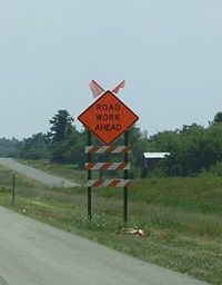
To ensure maximum visibility, existing signs and other physical features (trees, sidewalks, billboards, commercial signs, etc.) must be considered when locating work zone signs.
In order to maintain the systematic use of yellow or fluorescent yellow-green backgrounds for pedestrian, bicycle, and school warning signs in a jurisdiction, the yellow or fluorescent yellow-green background for pedestrian, bicycle, and school warning signs may be used in TTC zones.
616.6.2.2 Flags, Advance Warning Rail System and Warning Lights on Signs
During daytime hours, all active signs within the first advance warning area shall be enhanced with flags. Active signs provide information to the traveling public, signs covered or laying down are not deemed active. Flagger Ahead (WO20-7a) and TRUCK CROSSING (WO8-6) shall have flags regardless of the location within the work zone. Additional signs within the work zone may be enhanced with flags at the district’s discretion, although such practice should be infrequent.
All flag assemblies mentioned above must be quantified in the plans and paid for as Pay Item 616.10.09, Flag Assembly, per each.
The “Advance Warning Rail System” (AWRS) shall consist of three barricade rails used to enhance the target value of certain signs on long-term stationary operations. The AWRS is only installed on the first occurrence of the ROAD/BRIDGE WORK AHEAD (WO20-1) signs on the mainline roadway. The following are, but are not limited to, ways to install the AWRS:
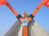
- 1. The three barricade rails may be attached to U-channel, wood or PSST posts, according to the minimum sign area (sign and rails) as located in Table B of Standard Plan 616.10.
- 2. A crashworthy skid-mounted sign and rail assembly.
- 3. The sign and three-rail system may be mounted as separate crashworthy devices. The rail system shall be located directly in front of the sign with 7 ft. to 10 ft. separating the two devices.
Flashing warning lights may be used in conjunction with signs.
Standard. When standard orange flags or flashing warning lights are used in conjunction with signs, they shall not block the sign face.
616.6.2.3 Sign Dimension
Work zone warning signs are typically be 48 in. x 48 in., diamond-shaped, black on orange signs with MoDOT fluorescent orange sheeting. Work zone regulatory signs are identical to permanent regulatory signs with MoDOT Type 3 sheeting. Work zone guide signs are generally rectangular in shape and have a black legend on orange background with MoDOT fluorescent orange sheeting; but may come in different sizes, shapes, colors and sheeting depending on type and purpose of the signing. Sometimes a plate or plaque is affixed to a work zone sign or mounted below it to customize the sign. For additional discussion on enhancements, refer to EPG 616.6.2.2 Flags, Advance Warning Rail System and Warning Lights on Signs.
Sign dimensions for contract projects are located in Standard Plan 616.10 and for maintenance projects are located in the MGS-04-01 Roll-up Signs. Maintenance projects may require other signs, NO CENTER LINE, SHOULDER DROP-OFF, UNEVEN LANE, BUMP, etc., which dimensions are located in standard plan 616.10. Non-standard work zone signs (i.e., legends or sizes not shown on Standard Plan 616.10) are to be designed with the assistance of Traffic. Correspondence with Traffic on this design is to indicate these are work zone signs. The non-standard work zone signs are to be detailed in the plans and listed under “Miscellaneous Signs” on the D-2BS sheet.
616.6.3 Sign Placement (MUTCD 6F.03)
616.6.3.1 Sign Location
Guidance. Signs should be located on the right-hand side of the roadway unless otherwise provided in the EPG. Examples of signs located on both the left-hand and right-hand side of the roadway is divided highways. Sign location information is located in EPG 616.8 Typical Applications and EPG 903 Highway Signing.
616.6.3.2 Sign Height
Support. The provisions of this Section regarding mounting height apply unless otherwise provided for a particular sign elsewhere in the EPG.
Standard. Rural Undivided Highways: The minimum height, measured vertically from the bottom of the sign to the elevation of the near edge of the pavement, of signs installed at the side of the road in rural areas shall be 5 ft. (see Standard Plan 616.10).
Urban or Rural Divided Highways: The minimum height, measured vertically from the bottom of the sign to the top of the curb, or in the absence of curb, measured vertically from the bottom of the sign to the elevation of the near edge of the traveled way, of signs installed at the side of the road in business, commercial, or residential areas where parking or pedestrian movements are likely to occur, or where the view of the sign might be obstructed, shall be 7 ft. (see Standard Plan 616.10).
The minimum height, measured vertically from the bottom of the sign to the sidewalk, of signs installed above sidewalks, bicycle facilities, or areas designated for pedestrian or bicycle traffic shall be 7 feet.
Guidance. Further guidance for the above Rural Undivided Highway and Urban or Rural Divided Highways paragraphs. For long-term duration projects, post or type 1 portable sign supports should be 5 ft. or 7 ft. depending on rural or urban applications. For short-term duration projects (up to 3 days), signs may be mounted on type 2 portable sign supports and should have a minimum height of 12 inches. Additional mounting heights for signs located on barrier and vehicles is located in Standard Plan 616.10.
Option. The height to the bottom of a secondary sign or plaque mounted below another sign may be 1 foot less than the height provided as shown in Standard Plan 616.10.
Guidance. Neither portable nor permanent sign supports should be located on sidewalks, bicycle facilities, or areas designated for pedestrian or bicycle traffic. If the bottom of a secondary sign that is mounted below another sign is mounted lower than 7 ft. above a pedestrian sidewalk or pathway (see EPG 616.4.2), the secondary sign should not project more than 4 in. into the pedestrian facility.
Standard. Where it has been determined that the accommodation of pedestrians with disabilities is necessary, signs shall be mounted and placed in accordance with Section 4.4 of the “Americans with Disabilities Act Accessibility Guidelines for Buildings and Facilities (ADAAG)” (see EPG 900.1.11).
Signs mounted on barricades and barricade/sign combinations shall be crashworthy (EPG 616.6.68).
616.6.3.3 Sign Mounting and Payment
Standard. Sign mounting shall be crashworthy. Standard Plan 616.10 and Standard Plan 903.03 show the following: sign mounting requirements, post size and quantities requirements, and post installation details. The standard drawings show detail information for use of signs on posts, barrier, vehicles, and barricades. Where large signs having an area exceeding 50 sq. ft. are installed on multiple breakaway posts, the clearance from the ground to the bottom of the sign shall be at least 7 feet.
Support. If alterations are made to specific traffic control device supports that have been successfully crash tested in accordance with NCHRP Report 350, the altered supports might not be considered to be crashworthy.
The sign mounting method is dependent upon the contractor’s operations and is not to be dictated on the plans. See Standard Plan 616.10 for mounting methods and Standard Plan 903.03 for post installation requirements. Sign relocation is only paid for post-mounted signs. MoDOT does not pay for temporary or portable sign relocations. If the designer judges post-mounted signs will be used on a project, a pay item for Relocated Signs (616-10.10) is to be included in the contract documents. Sign quantities are tabulated on the plans and are paid for by the square foot. The tabulation and any notes concerning the signs shall be consistent throughout the traffic control plan.
If the sign cannot be mounted by a method specified by EPG 903.4 Overhead Guide Sign Mounting, Standard Plan 616.10 or Standard Plan 903.03, the mounting method is also to be specified in the plans.
616.6.4 Sign Maintenance (MUTCD 6F.04)
Guidance. Signs should be properly maintained for cleanliness, visibility and correct positioning.
Signs that have lost significant legibility should be promptly replaced.
EPG 616.19 Quality Standards for Temporary Traffic Control Devices provides examples of sign maintenance.
Support. Sec 1063 contains information regarding the retroreflectivity of signs, including the signs that are used in TTC zones.
616.6.5 Regulatory Sign Authority (MUTCD 6F.05)
Support. Regulatory signs inform road users of traffic laws or regulations and indicate the applicability of legal requirements that would not otherwise be apparent.
Standard. Regulatory signs shall be authorized by the public agency or official having jurisdiction and shall conform with EPG 903.5 Regulatory Signs.
616.6.6 Regulatory Sign Design (MUTCD 6F.06)
Standard. TTC regulatory signs shall comply with the Standards for regulatory signs presented in EPG 903.5 Regulatory Signs and in the FHWA’s Standard Highway Signs and Markings book (see MUTCD 1A.11).
Support. Regulatory signs are generally rectangular with a black legend and border on a white background. Exceptions include the STOP, YIELD, DO NOT ENTER, WRONG WAY and ONE WAY signs.
616.6.7 Regulatory Sign Applications (MUTCD 6F.07)
Standard. If a TTC zone requires regulatory measures different from those existing, the existing permanent regulatory devices shall be removed or covered and superseded by the appropriate temporary regulatory signs. This change shall be made in compliance with applicable ordinances or statutes of the jurisdiction.
Support. Regulatory sign information is available in the below table. EPG links and MUTCD section info are located within the table. Additional information of regulatory signs used in TTC applications are located after the table.
Table 616.6.7
| Sign | Title | Sign No. | EPG Article | MUTCD section |
|---|---|---|---|---|
| STOP | R1-1 | 903.5.4 | 2B.05 | |
| YIELD | R1-2 | 903.5.5 | 2B.11 | |
| TO ONCOMING TRAFFIC (Plaque) | R1-2a | 903.5.5 | 2B.11 | |
| ALL-WAY (Plaque) | R1-3 | 903.5.4 | 2B.05 | |
| SPEED LIMIT XX | R2-1 | 616.12 & 903.5.7 | 2B.13 | |
| No Right Turn (Symbol) | R3-1 | 903.5.11 | 2B.18 | |
| No Left Turn (Symbol) | R3-2 | 903.5.11 | 2B.18 | |
| NO TURNS | R3-3 | 903.5.11 | 2B.18 | |
| No U-Turn (Symbol) | R3-4 | 903.5.11 | 2B.18 | |
| LEFT LANE MUST TURN LEFT | R3-7L | 903.5.12 | 2B.19 | |
| RIGHT LANE MUST TURN RIGHT | R3-7R | 903.5.12 | 2B.19 | |
| DO NOT PASS | R4-1 | 903.5.16 | 2B.28 | |
| PASS WITH CARE | R4-2 | 903.5.17 | 2B.29 | |
| KEEP RIGHT (Horizontal Arrow) | R4-7a | 903.5.19 | 2B.32 | |
| KEEP LEFT (Horizontal Arrow) | R4-8a | 903.5.19 | 2B.32 | |
| DO NOT ENTER | R5-1 | 903.5.20 | 2B.37 | |
| WRONG WAY | R5-1a | 903.5.21 | 2B.38 | |
| ONE WAY ARROW (Left) | R6-1L | 903.5.23 | 2B.40 | |
| ONE WAY ARROW (Right) | R6-1R | 903.5.23 | 2B.40 | |
| ONE WAY (Left) | R6-2L | 903.5.23 | 2B.40 | |
| ONE WAY (Right) | R6-2R | 903.5.23 | 2B.40 | |
| STOP HERE ON RED (45⁰ Arrow) | R10-6 | 903.5.30 | 2B.53 |
R1-1 (STOP). STOP signs in work zones are used where a side street connection is currently under stop control is temporarily relocated. Due to temporary changes in geometrics or traffic patterns, multi-way STOP signs may be needed.
R1-2a (TO ONCOMING TRAFFIC). The TO ONCOMING TRAFFIC plaque is used to supplement the YIELD sign for one-lane, two-way operations. See EPG 616.3.10.
R2-1 (SPEED LIMIT XX). SPEED LIMIT signs are used in work zones to set enforceable speed limits through the work zone. Work zone speed limits are based on guidelines in EPG 616.12 Work Zone Speed Limits.
Speed Limit and Strobe Light Assembly. This assembly consists of signs R2-1 (SPEED LIMIT XX), S4-4 (WHEN FLASHING), G023-1 (WORK ZONE) and two strobe lights arranged as shown on Standard Plan 616.10. This assembly is used on multilane high volume roadways when construction operations are not permitted during peak hours. All normal travel lanes must be available and normal speed permitted through the work zone during peak volume hours. The speed limit designated on the assembly is only enforceable when the strobe lights are operating. This assembly is a substitute for normal advance signing required to reduce speed through the work zone and eliminates covering or removing the speed control signs during non-working hours. The assembly is only to be used in long-term stationary work zones with restrictions on working hours. The SPEED LIMIT XX AHEAD sign is not used in advance of the speed limit and strobe light assembly. This assembly is paid per each and includes all signs, strobes, posts and installation.
R4-1 (DO NOT PASS). The DO NOT PASS sign may be used on a two- or three-lane roadway at the beginning of and at intervals within, a work zone where passing is restricted, or in conjunction with the WORK ZONE FINE sign. A typical application of this sign is on a temporary two-lane, two-way operation on a normally divided highway.
R4-2 (PASS WITH CARE). The PASS WITH CARE sign is to only be used in conjunction with the “WORK ZONE FINE” sign set-up.
R10-6 (STOP HERE ON RED). This sign may be used at signalized intersections to supplement the pavement stop bar. This sign is typically used with the signal or automatic flagger assistance device controlled one-lane, two-way operations.
616.6.8 ROAD CLOSED Sign (R11-2) (MUTCD 6F.08)

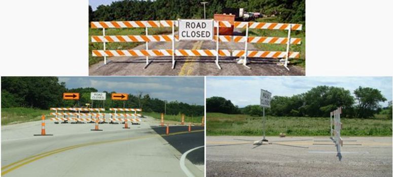
Guidance. The ROAD CLOSED (R11-2) sign should be used when the roadway is closed to all road users except contractors’ equipment or officially authorized vehicles. The R11-2 sign should be accompanied by appropriate warning and detour signing (see Fig. 616.8.8 - MT and Fig. 616.8.9 - MT).
Guidance. The ROAD CLOSED sign should be installed at or near the center of the roadway on or above a Type 3 Barricade that closes the roadway (see EPG 616.6.68 Type 1 or 3 Barricades).
Standard. The ROAD CLOSED sign shall not be used where road user flow is maintained through the TTC zone with a reduced number of lanes on the existing roadway or where the actual closure is some distance beyond the sign.
616.6.9 Local Traffic Only Signs (R11-3a, R11-4) (MUTCD 6F.09)
 |
 |
Guidance. The Local Traffic Only signs should be used where road user flow detours to avoid a closure some distance beyond the sign, but where local road users can use the roadway to the point of closure. These signs should be accompanied by appropriate warning and detour signing (see Fig. 616.8.8 - MT and Fig. 616.8.9 - MT).
In rural applications, the Local Traffic Only sign should have the legend ROAD CLOSED XX MILES AHEAD, LOCAL TRAFFIC ONLY (R11-3a).
In urban areas, the legend ROAD CLOSED TO THRU TRAFFIC (R11-4) should be used.
616.6.10 Weight Limit Signs (R12-1, R12-2, R12-5) (MUTCD 6F.10)
 |
 |
 |
Standard. A Weight Limit sign , that shows the gross weight or axle weight that is permitted on the roadway or bridge, shall be consistent with state or local regulations and shall not be installed without the approval of the authority having jurisdiction over the highway.
When weight restrictions are imposed because of the activity in a TTC zone, a marked detour shall be provided for vehicles weighing more than the posted limit.
616.6.11 STAY IN LANE Sign (R4-9) (MUTCD 6F.11)
MoDOT does not use this sign.
616.6.12 Work Zone and Higher Fines Signs and Plaques (MUTCD 6F.12)
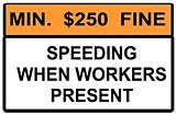 |
Standard. A WORK ZONE (G20-5aP) plaque shall be mounted above all SPEED LIMIT signs, except on the SPEED LIMIT signs at the end of the work zone to return traffic to the normal posted speed. These plaques shall be mounted above all DO NOT PASS and PASS WITH CARE signs. These signs shall be used on the above signs regardless of whether the WORK ZONE FINE sign is used.
WORK ZONE FINE sign and SPEEDING/PASSING (plate) information and guidelines is available in EPG 616.12 Work Zone Speed Limits.
616.6.13 PEDESTRIAN CROSSWALK Sign (R9-8) (MUTCD 6F.13)

Option. The PEDESTRIAN CROSSWALK (R9-8) sign may be used to indicate where a temporary crosswalk has been established.
Standard. If a temporary crosswalk is established, it shall be accessible to pedestrians with disabilities in accordance with EPG 616.4.2.
616.6.14 SIDEWALK CLOSED Signs (R9-9, R9-10, R9-11, R9-11a) (MUTCD 6F.14)
Guidance. SIDEWALK CLOSED signs should be used where pedestrian flow is restricted. Bicycle/Pedestrian Detour (M4-9a) signs or Pedestrian Detour (M4-9b) signs should be used where pedestrian flow is rerouted (see EPG 616.6.59).
The SIDEWALK CLOSED (R9-9) sign should be installed at the beginning of the closed sidewalk, at the intersections preceding the closed sidewalk, and elsewhere along the closed sidewalk as needed.
The SIDEWALK CLOSED, (ARROW) USE OTHER SIDE (R9-10) sign should be installed at the beginning of the restricted sidewalk when a parallel sidewalk exists on the other side of the roadway.
The SIDEWALK CLOSED AHEAD, (ARROW) CROSS HERE (R9-11) sign should be used to indicate to pedestrians that sidewalks beyond the sign are closed and to direct them to open crosswalks, sidewalks, or other travel paths.
The SIDEWALK CLOSED, (ARROW) CROSS HERE (R9-11a) sign should be installed just beyond the point to which pedestrians are being redirected.
Support. These signs are typically mounted on a detectable barricade to encourage compliance and to communicate with pedestrians that the sidewalk is closed. Printed signs are not useful to many pedestrians with visual disabilities. A barrier or barricade detectable by a person with a visual disability is sufficient to indicate that a sidewalk is closed. If the barrier is continuous with detectable channelizing devices for an alternate route, accessible signing might not be necessary. An audible information device is needed when the detectable barricade or barrier for an alternate channelized route is not continuous.
Further guidance is located in EPG 616.4 Pedestrian and Worker Safety and EPG 616.24 Traffic Control for Non-Motorized Traffic.
616.6.15 Special Regulatory Signs (MUTCD 6F.15)
Guidance. Special regulatory signs may be used based on engineering judgment consistent with regulatory requirements. All special regulatory sign shall be designed with the assistance of Central Office Traffic Division. Special regulatory signs should comply with the general requirements of color, shape and alphabet size and series. The sign message should be brief, legible and clear.
616.6.16 Warning Sign Function, Design and Application (MUTCD 6F.16)
Support. TTC zone warning signs notify road users of specific situations or conditions on or adjacent to a roadway that might not otherwise be apparent.
Standard. TTC warning signs shall comply with the Standards for warning signs presented in EPG 903.6 and in FHWA’s Standard Highway Signs and Markings book (see EPG 900.1.11). Except for incident management warning signs, TTC warning signs shall be diamond-shaped with a black legend and border on an MoDOT fluorescent orange background, except for the W10-1 sign which shall have a black legend and border on a MoDOT Type 3 yellow background, and except for signs that are required or recommended in EPG 903 to have fluorescent yellow-green backgrounds. MoDOT has special specifications of fluorescent sheeting.
The letter “O” is added to the TTC sign designation of WO, GO, EO, MO, etc. to represent the color orange, which provides a separate nomenclature from the permanent warning signs.
Option. Warning signs used for TTC incident management situations may have a black legend and border on a fluorescent pink background (see EPG 616.9 Control of Traffic Through Traffic Incident Management Areas).
Mounting or space considerations may justify a change from the standard diamond shape (see Fig. 616.2.4).
In emergencies with coordination with district work zone coordinators, available warning signs having yellow backgrounds may be used if signs with orange or fluorescent pink backgrounds are not at hand.
Guidance. Where any part of the roadway is obstructed or closed by work activities or incidents, advance warning signs should be installed to alert road users well in advance of these obstructions or restrictions.
Where road users include pedestrians, the provision of supplemental audible information or detectable barriers or barricades should be considered for people with visual disabilities.
Support. Detectable barriers or barricades communicate very clearly to pedestrians who have visual disabilities that they can no longer proceed in the direction that they are traveling.
Option. Advance warning signs may be used singly or in combination.
Where distances are not displayed on warning signs as part of the message, a supplemental plaque with the distance legend may be mounted immediately below the sign on the same support.
616.6.17 Position of Advance Warning Signs (MUTCD 6F.17)
Guidance. Where highway conditions permit, warning signs should be placed in advance of the TTC zone at varying distances depending on roadway type, condition, and posted speed. EPG 616.3 Temporary Traffic Control Elements contains information regarding the spacing of advance warning signs.
Where multiple advance warning signs are needed on the approach to a TTC zone, the ROAD WORK AHEAD (W20-1) sign should be the first advance warning sign encountered by road users.
Support. Various conditions, such as limited sight distance or obstructions that might require a driver to reduce speed or stop, might require additional advance warning signs.
Option. As an alternative to a specific distance on advance warning signs, the word AHEAD may be used.
Option. Utility work, maintenance or minor construction can occur within the TTC zone limits of a major construction project and additional warning signs may be needed.
Guidance. Utility, maintenance, and minor construction signing and TTC should be coordinated with district work zone coordinators so that road users are not confused or misled by the additional TTC devices.
616.6.17.1 Signing for One-Lane, Two-Way Resurfacing Operations
To expedite moving resurfacing operations on one-lane, two-way roadways, a third and fourth series of construction zone signs is to be provided. This configuration is to be shown in the TCP and appropriate sign quantities are to be provided. A maximum length of work area may also be shown in the TCP.
616.6.17.2 Signs in Narrow Medians
Where signs are installed in narrow medians, the size of signs may need to be reduced to provide sufficient lateral clearance. It is important to retain the diamond shape of warning signs as much as possible. It is not acceptable to use rectangular shapes in lieu of diamond shapes, but the corners of the diamond shaped signs may be clipped to reduce sign width. It is preferable to use 36 in. warning signs rather than to cut the corners of 48 in. signs. Fig. 616.2.4 provides guidelines for signs in narrow medians. Any other sign sizes or shapes used that are not shown in the standard plans are shown in the plans with a layout including lettering size and series.

616.6.17.3 Signing for Mobile Operations
Mobile operations are work activities that move along the road either intermittently or continuously. During mobile operations the signs and traffic control devices are normally attached to protective or warning trucks moving with the operation. Stationary signs may also be installed at the beginning and end of sections covered by the mobile operation. For intermittent operations, the stops normally do not exceed 15 minutes. For intermittent lane closures with stops exceeding 15 minutes, stationary traffic control is to be considered. In addition to warning signs, revolving lights, flashing arrow panels and truck-mounted attenuators are also commonly used with mobile operations. Refer to Maintenance discussion concerning TMAs for additional information.
The most common mobile operation used with construction projects is the installation of pavement marking. Refer to EPG 620.1 for additional information. For other mobile operations, consult Part VI of the MUTCD.
616.6.18 ROAD/BRIDGE/RAMP WORK Sign (WO20-1) (MUTCD 6F.18)
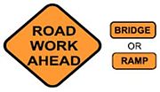
Guidance. The ROAD/BRIDGE/RAMP WORK (WO20-1) sign , which serves as a general warning of obstructions or restrictions, should be located in advance of the work space or any detour, on the road where the work is taking place.
Where traffic can enter a TTC zone from a crossroad or a major (high-volume) driveway, an advance warning sign should be used on the crossroad or major driveway.
Standard. The ROAD WORK (WO20-1) sign shall have the legend ROAD/BRIDGE/RAMP WORK, XX FEET, XX MILES, or AHEAD.
616.6.19 DETOUR Sign (WO20-2) and Detour Route Assembly (MUTCD 6F.19)
| Sign | Title | Sign No. | EPG Article | MUTCD section |
|---|---|---|---|---|
 |
DETOUR AHEAD | WO20-2 | 616.6.19 | 6F.19 |
 |
Detour Route Assembly | SPECIAL | Fig. 616.2.1 and Fig. 616.8.9 - MT | n/a |
Guidance.The DETOUR (WO20-2) sign and Detour Route Assemblies should be used in advance of a road user detour over a different roadway or route.
Standard. The DETOUR sign shall have the legend DETOUR, XX FEET, XX MILES, or AHEAD.
These signs are used in advance of a signed detour. These signs are installed only on the route being detoured. Detour signing is used with these signs to guide drivers through the detour. These signs are not used with temporary bypasses or connections unless part of or the entire route is on other existing roadways.
Detour signing is used when a section of road is closed to through traffic and rerouted over other existing facilities. Detours are used when other methods of traffic control such as one-lane, two-way operations, lane closures or temporary bypasses cannot be used. Detours are provided over the shortest possible route around the closure that can sufficiently accommodate the traffic.
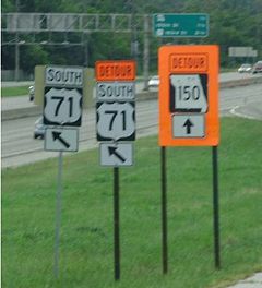
The existing traffic (AADT) on the roadway being closed and the detour route, as well as the facility types are considered when determining detour routes. State routes are preferred for detour use, but other local facilities may be considered. Fig. 616.8.8 - MT and Fig. 616.8.9 - MT show a typical detour of a road closed beyond the junction. Detours for multilane roadways, expressways and freeways can be quite complex and may require a combination of lane closures and modification of existing guide signs as well as detour signing.
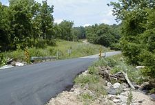
Where city streets, county roads and other public roads are detoured due to roadwork, detour signing is provided showing the name or number of the road being detoured. Detour signing is provided at each junction through the detour route as well as confirmation signs where there are long detour sections over the same route. Detour signing is not used for temporary bypasses or connections.
Alternate route signing may be used where lane closures or physical height or width restrictions will have a significant effect on traffic and a viable alternate route is available. Alternate route signing may also be used where temporary bridge weight restrictions are imposed during construction. Alternate route signing is similar to detour signing except the DETOUR plaque is replaced with an ALTERNATE plaque.
Additional information is located in EPG 616.3.9 Detours and Diversions.
616.6.20 ROAD (STREET) CLOSED Sign (WO20-3) (MUTCD 6F.20)
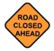
Guidance. The ROAD CLOSED (WO20-3) sign should be used in advance of the point where a highway is closed to all road users, or to all but local road users. These signs are used with detour signing after the ROAD CLOSED XX MILES AHEAD sign and before the ROAD CLOSED sign.
Standard. The ROAD CLOSED sign shall have the legend ROAD CLOSED, XX FEET, XX MILES, or AHEAD.
616.6.21 ONE LANE ROAD Sign (WO20-4) (MUTCD 6F.21)
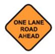
Standard. The ONE LANE ROAD (WO20-4) sign shall be used only in advance of that point where motor vehicle traffic in both directions must use a common single lane (see 616.3.10). It shall have the legend ONE LANE ROAD, XX FEET, XX MILES, or AHEAD.
616.6.22 Lane(s) Closed Signs (WO20-5, WO20-5a) (MUTCD 6F.22)
 |
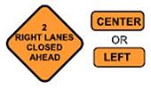 |
Standard. The Lane(s) Closed sign shall be used in advance of that point where one or more through lanes of a multi-lane roadway are closed.
For a single lane closure, the Lane Closed (WO20-5) sign shall have the legend RIGHT (LEFT) LANE CLOSED, XX FEET, XX MILES, or AHEAD. Where two adjacent lanes are closed, the WO20-5a sign shall have the legend XX RIGHT (LEFT) LANES CLOSED, XX FEET, XX MILES, or AHEAD.
Guidance. The CENTER LANE CLOSED AHEAD sign should be used in advance of that point where work occupies the center lane(s) and approaching motor vehicle traffic is directed to the right or left of the work zone in the center lane.
616.6.23 CENTER LANE CLOSED AHEAD Sign (W9-3) (MUTCD 6F.23)
See EPG 616.6.22.
616.6.24 Lane Ends Sign (Special Signs RIGHT LANE CLOSED (WO20-6a) and MERGE (Arrow)) (MUTCD 6F.24)

Guidance. MoDOT should use the signs RIGHT (LEFT/CENTER) LANE CLOSED (MoDOT WO20-6a) and MERGE (ARROW) (MoDOT) to warn of the reduction in the number of lanes for moving motor vehicle traffic in the direction of travel on a multi-lane roadway.
616.6.25 ON RAMP Plaque (W13-4P) (MUTCD 6F.25)
MoDOT does not use this sign.
616.6.26 ROAD/BRIDGE/RAMP NARROWS Sign (WO5-1) (MUTCD 6F.26)

Guidance. The ROAD/BRIDGE/RAMP NARROWS (WO5-4) sign should be used in advance of the point where work on a road/bridge/ramp reduces the normal width of the road/bridge/ramp along a part or all of the road/bridge/ramp.
616.6.27 SLOW TRAFFIC AHEAD Sign (W23-1) (MUTCD 6F.27)
MoDOT does not use this sign.
616.6.28 EXIT GORE, EXIT OPEN and EXIT CLOSED Signs (EO5-1, EO5-2, EO5-2a) (MUTCD 6F.28 and 2E.37)
 |
 |
 |
Guidance. Temporary EXIT GORE (EO5-1) signs should be provided when work in the vicinity of off-ramps shifts the gore point of the ramp.
Option. An EXIT OPEN (EO5-2) or EXIT CLOSED (EO5-2a) sign may be used to supplement other warning signs where work is being conducted in the vicinity of an exit ramp and where the exit maneuver for vehicular traffic using the ramp is different from the normal condition.
Guidance. When an exit ramp is closed, an EXIT CLOSED sign panel with a black legend and border on an orange background should be placed diagonally across the interchange/intersection guide signs.
616.6.29 EXIT ONLY Sign (E5-3) (MUTCD 6F.29)
MoDOT does not use this sign.
616.6.30 NEW TRAFFIC PATTERN AHEAD Sign (W23-2) (MUTCD 6F.30)
MoDOT does not use this sign.
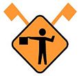
616.6.31 Flagger (WO20-7) and BE PREPARD TO STOP (WO3-4) signs (MUTCD 6F.31)
 |
 |
Guidance. The Flagger (WO20-7) symbol sign should be used in advance of any point where a flagger is stationed to control road users. These signs should be displayed when a flagger is present and should be covered when the flagger is not present.
Option. The Flagger (WO20-7) symbol sign may be used with the BE PREPARED TO STOP (WO3-4) sign . The BE PREPARED TO STOP (WO3-4) sign is used where conditions require traffic to stop for flagger-controlled truck/equipment crossings or entrances and temporary road closures where traffic is allowed to proceed unimpeded until access is needed. This sign may also be used in one-lane, two-way flagging operations where no work zone speed limit is established.
616.6.32 Two-Way Traffic Sign (WO6-3) (MUTCD 6F.32)
Guidance. When one roadway of a normally divided highway is closed, with two-way vehicular traffic maintained on the other roadway, the Two-Way Traffic (WO6-3) sign should be used at the beginning of the two-way vehicular traffic section and at intervals to remind road users of opposing vehicular traffic.
616.6.33 Workers Signs (W21-1, W21-1a) (MUTCD 6F.33)
MoDOT does not use this sign.
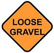
616.6.34 FRESH OIL Sign (WO21-2), LOOSE GRAVEL (WO8-7) or FRESH OIL/LOOSE GRAVEL Sign (Special) (MUTCD 6F.34)
 |
 |
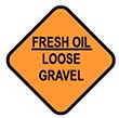 |
Guidance. The FRESH OIL (W21-2), LOOSE GRAVEL (WO8-7) or FRESH OIL/LOOSE GRAVEL Sign should be used to warn road users of the surface treatment.
616.6.35 ROAD MACHINERY AHEAD Sign (W21-3) (MUTCD 6F.35)
MoDOT does not use this sign.
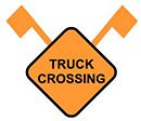
616.6.36 Motorized Traffic Signs: TRUCK CROSSING (WO8-6) and TRUCK ENTRANCE (SPECIAL WO8-6c) (MUTCD 6F.36)
 |
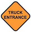 |
Option. TRUCK CROSSING (WO8-6) and TRUCK ENTRANCE (Special WO8-8c) signs may be used to alert road users to locations where unexpected travel on the roadway or entries into or departures from the roadway by construction vehicles might occur.
Support. These locations might be relatively confined or might occur randomly over a segment of roadway.
616.6.37 Shoulder Work Signs (WO21-5b) (MUTCD 6F.37)

Support. Shoulder Work signs warn of maintenance, reconstruction, or utility operations on the highway shoulder where the roadway is unobstructed.
Standard. The Shoulder Work sign shall have the legend SHOULDER WORK AHEAD (W21-5b).
Option. The Shoulder Work sign may be used in advance of the point on a non-limited access highway where there is shoulder work. It may be used singly or in combination with a ROAD WORK NEXT XX MILES or ROAD WORK AHEAD sign.
Guidance. On freeways and expressways, the SHOULDER WORK AHEAD (WO21-5b) sign should be preceded by a ROAD WORK AHEAD sign.
616.6.38 SURVEY CREW AHEAD Sign (WO21-6) (MUTCD 6F.38)

Guidance. The SURVEY CREW AHEAD (WO21-6) sign should be used to warn of surveying crews working in or adjacent to the roadway.
616.6.39 UTILITY WORK Sign (WO21-7) (MUTCD 6F.39)
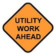
Option. For permit projects, the UTILITY WORK (WO21-7) sign may be used as an alternate to the ROAD WORK (WO20-1) sign for utility operations on or adjacent to a highway.
Standard. The UTILITY WORK sign shall carry the legend UTILITY WORK, XX FEET, XX MILES, or AHEAD.
616.6.40 Signs for Blasting Areas (MUTCD 6F.40)
These signs are not shown on the traffic control plan due to the various methods of detonation and various locations within a project that may require blasting. These signs, if used, are furnished by the contractor, at the contractor's expense. Reference to Blasting Area requirements are located in the following: Specification Section 616, EPG 203 Roadway and Drainage Excavation, Embankment, and Compaction, MUTCD sections 6F.40 – 43, and MUTCD Figure 6H-2: Blasting Zone.
616.6.41 BLASTING ZONE AHEAD Sign (W22-1) (MUTCD 6F.41)
Refer to EPG 616.6.40.
616.6.42 TURN OFF 2-WAY RADIO AND CELL PHONE Sign (W22-2) (MUTCD 6F.42)
Refer to EPG 616.6.40.
616.6.43 END BLASTING ZONE Sign (W22-3) (MUTCD 6F.43)
Refer to EPG 616.6.40.
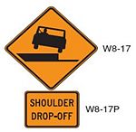
616.6.44 Shoulder Signs and Plaque (WO8-4, WO8-17 and WO8-17P) (MUTCD 6F.44)
 |
 |
The SOFT SHOULDER (WO8-4) sign may be used to warn of a soft shoulder condition.
Guidance. The SHOULDER DROP OFF (WO8-17) sign should be used when an unprotected shoulder drop-off, adjacent to the travel lane, is deeper than 2 in. for a continuous length along the roadway, based on engineering judgment. This sign is to be used as shown in Standard Plans 619.10 and 620.10.
When the SHOULDER DROP-OFF signs are in-placed for greater than three days, the SHOULDER DROP-OFF plaque should be used in addition with the SHOULDER DROP-OFF sign.
616.6.45 UNEVEN LANES Sign (WO8-11) (MUTCD 6F.45)

Guidance. The UNEVEN LANES (WO8-11) sign should be used during operations that create a difference in elevation between adjacent lanes that are open to travel. This sign is to be used as shown in Standard Plans 619.10 and 620.10.
616.6.46 STEEL PLATE AHEAD Sign (WO8-24) (MUTCD 6F.46)
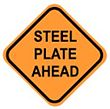
This sign is used by Maintenance employees. See EPG 616.23.2.7.5.
616.6.47 NO CENTER LINE Sign (WO8-12) (MUTCD 6F.47)
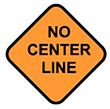
These signs are black-on-orange warning signs used on two-lane and two-lane with auxiliary lane facilities where no-passing zone centerline marking is eliminated for 200 linear ft. or more. These signs are used in combination with temporary pavement marking. These signs are placed in advance of the missing no-passing zone centerline markings area at the recommended sign spacing. For extended areas continuously or intermittently missing no-passing centerline marking, NO CENTER LINE signs should also be installed within 150 ft. after the intersection of a state route and at two-mile spacing throughout the affected area. Upon the discretion of the engineer or supervisor, additional NO CENTER LINE signs may be installed within 150 ft. after other intersections. When a sign placed at the two-mile interval and another sign placed after an intersection fall within one-eighth mile of each other, the sign placed at the two-mile interval may be eliminated. Standard Plan 620.10 shows the configuration for these signs and pavement markers on a two-lane roadway. This layout is to also be included in the TCP.
When temporary pavement markings and/or NO CENTER LINE signs are necessitated by either a change in roadway use or the elimination of permanent pavement markings, the following provisions shall be incorporated into the operation:
- Those performing the operation shall be responsible for coordinating the procurement, installation, maintenance and removal, as applicable, of pavement markings, temporary or permanent, and any NO CENTER LINE signs.
- Temporary pavement markings and any NO CENTER LINE signs shall be in place prior to opening a roadway to traffic. On two-lane highways with AADTs less than 1000, certain material and operations do not allow the practical application of these markings (e.g., chip seal, cold mix curing, fly coating, etc.), installation of temporary pavement markings may be delayed up to 5 working days, initiated by the elimination of the permanent pavement markings, provided the required NO CENTER LINE signs are in place as prescribed previously prior to opening the facility to traffic.
- Contract Projects – Permanent pavement marking shall be installed in accordance with Sec 620 Pavement Marking.
- Maintenance Operations – Permanent pavement markings should be installed no later than 14 calendar days after any operation has been completed. However, delays in installation should be minimized where possible.
- Removal or obliteration of all pavement markings shall be complete and leave minimal pavement scarring. Concealing any pavement marking with black paint or asphalt is not acceptable.
616.6.48 Turn, Curve, Reverse Curve, Double and Triple Arrow Reverse Curve and ALL LANE Signs (WO1-1, 1-2, 1-3, 1-4 and WO24-1cP Series) (MUTCD 6F.48)
WO1-1 and WO1-3 Series (Turn and Reverse Turn). These symbolic signs are used when the anticipated posted speed of a turn or reverse turn is 30 mph or less.
WO1-2 and WO1-4 Series (Curve and Reverse Curve). These symbolic signs are used when the anticipated posted speed of a curve or reverse curve is greater than 30 mph and less than the posted speed limit.
Guidance. In order to give road users advance notice of a lane shift, a Reverse Curve (WO1-4, WO1-4b, or WO1-4c) sign should be used when a lane (or lanes) is being shifted to the left or right. If the design speed of the curves is 30 mph or less, a Reverse Turn (WO1-3) sign should be used.
Standard. If a Reverse Curve (or Turn) sign is used, the direction of the reverse curve (or turn) shall be appropriately illustrated. Except as provided below, the number of lanes illustrated on the sign shall be the same as the number of through lanes available to road users.
Option. Where two or more lanes are being shifted, a WO1-4 (or WO1-3) sign with an ALL LANES (WO24-1cP) plaque may be used instead of a sign that illustrates the number of lanes.
Where more than three lanes are being shifted, the Reverse Curve (or Turn) sign may be rectangular.
Table 616.6.48
| Sign | Title | Sign No. | EPG Article | MUTCD section |
|---|---|---|---|---|
| Turn | WO1-1 | 903.6.7 | 2C.07 | |
| Curve | WO1-2 | 903.6.7 | 2C.07 | |
| Reverse Turn | WO1-3 | 903.6.7 | 2C.07 | |
| Reverse Curve | WO1-4 | 903.6.7 | 2C.07 | |
| Double Arrow Reverse Curve | WO1-4b | 616.6.48 | 6F.48 | |
| Triple Arrow Reverse Curve | WO1-4c | 616.6.48 | 6F.48 | |
| ALL LANES (Plaque) | WO24-1cP | 616.6.48 | 6F.48 |
616.6.49 Double Reverse Curve, Double and Triple Arrow Double Reverse and ALL LANES Signs (WO24-1 Series) (MUTCD 6F.49)
Option. The Double Reverse Curve (WO24-1, WO24-1a or WO24-1b) sign may be used where the tangent distance between two reverse curves is less than 600 ft., thus making it difficult for a second Reverse Curve (WO1-4 series) sign to be placed between the curves. If the design speed of the curves is 30 mph or less, Double Reverse Turn signs should be used.
Standard. If a Double Reverse Curve (or Turn) sign is used, the direction of the double reverse curve (or turn) shall be appropriately illustrated. Except as provided below, the number of lanes illustrated on the sign shall be the same as the number of through lanes available to road users.
Option. Where two or more lanes are being shifted, a WO24-1 (or Double Reverse Turn sign showing one lane) sign with an ALL LANES (WO24-1cP) plaque may be used instead of a sign that illustrates the number of lanes.
Where more than three lanes are being shifted, the Double Reverse Curve (or Turn) sign may be rectangular.
Table 616.6.49
616.6.50 Other Warning Signs (MUTCD 6F.50)
Option. Advance warning signs may be used by themselves or with other advance warning signs.
Besides the warning signs specifically related to TTC zones, several other warning signs in EPG 903 Highway Signing may apply in TTC zones.
Standard. Except as provided in EPG 616.6.2, other warning signs that are used in TTC zones shall have black legends and borders on an MoDOT fluorescent orange background.
Below the table, additional information is provided for the following signs.
Table 616.6.50
| Sign | Title | Sign No. | EPG Article | MUTCD section |
|---|---|---|---|---|
| Horizontal Arrow (Symbol) | WO1-6 | 903.6.10 | 2C.12 | |
| Horizontal Arrow (Symbol on Permanent Barricade) | WO1-6a | 903.6.10 | 2C.12 | |
| Double Head Horizontal Arrow (Symbol) | WO1-7 | 903.6.38 | 2C.47 | |
| Double Head Horizontal Arrow (Symbol on Permanent Barricade) |
WO1-7a | 903.6.38 | 2C.47 | |
| Chevron (Symbol) | WO1-8 | 903.6.11 | 2C.09 | |
| Chevron (Symbol for Divided Highways) | WO1-8a | 903.6.11 | 2C.09 | |
| Stop Ahead (Symbol) | W03-1 | 903.6.28 | 2C.36 | |
| Yield Ahead (Symbol) | WO3-2 | 903.6.28 | 2C.36 | |
| Signal Ahead (Symbol) | WO3-3 | 903.6.28 | 2C.36 | |
| Reduced Speed Limit Ahead (Symbol) | WO3-5 | 616.12 & 903.6.30 | 2C.38 | |
| Merge Traffic (Symbol) | WO4-1(L or R) | 903.6.31 | 2C.40 | |
| ONE LANE BRIDGE | WO5-3 | 903.6.17 | 2C.21 | |
| NARROW LANES | SPECIAL WO5-5 | N/A | N/A | |
| Divided Highway End (Symbol) | WO6-1 | 903.6.17 | 2C.22 | |
| Divided Highway End (Symbol) | WO6-2 | 903.6.18 | 2C.23 | |
| BUMP | WO8-1 | 903.6.23 | 2C.28 | |
| DIP | WO8-2 | 903.6.23 | 2C.28 | |
| PAVEMENT ENDS | WO8-3 | 903.6.24 | 2C.30 | |
| Slippery When Wet (Symbol) | WO8-5 | 903.6.26 | 2C.32 | |
| GROOVED PAVEMENT | WO8-15 | N/A | 2C.33 | |
| Railroad Crossing | W010-1 | 903.20.6 | 8B.06 | |
| Double Down Arrow (Symbol) | WO12-1 | 903.6.19 | 2C.25 | |
| Low Clearance (Symbol) | WO12-2 | 903.6.22 | 2C.27 | |
| Overhead Low Clearance (Feet and Inches) | WO12-2a | 903.6.22 | 2C.27 | |
| Low Clearance (Plaque) | WO12-2x | N/A | N/A | |
| LOW CLEARANCE XX FT XX IN XX MILES AHEAD |
SPECIAL | N/A | N/A | |
| WIDTH RESTRICTION XX FT XX IN XX MILES AHEAD |
SPECIAL | N/A | N/A | |
| XXX FEET (Plaque) | WO16-2P | 903.6.45 | 2C.60 | |
| X MILE (Plaque) | WO16-3aP | 903.6.45 | 2C.55 | |
| WET PAINT (Arrow Pivots) | SPECIAL WO22-6e | N/A | N/A | |
| Type1 Object Marker | - | Std. Plan 612.20 | 2C.63 | |
| Type 3 Object Marker | - | Std. Plan 616.10 | 2C.63 |
WO1-6 and WO1-7 Series (Horizontal Arrow and Double Head Horizontal Arrow). These symbolic signs are used in conjunction with Type III barricades. The HORIZONTAL ARROW signs are also used in conjunction with the TURN and REVERSE TURN series signs.
WO3-1a (Stop Ahead). This symbolic sign is used in advance of a STOP sign not visible for a sufficient distance to permit the driver to bring the vehicle to a complete stop. This sign may also be used where a driver would not normally expect STOP sign control.
WO3-2a (Yield Ahead). This symbolic sign is used in advance of a YIELD sign not visible for a sufficient distance to permit the driver to bring the vehicle to a stop at the YIELD sign or where a driver would not normally expect YIELD sign control.
WO3-3 (Signal Ahead). This symbolic sign is used in advance of a traffic signal where the minimum visibility requirements described in EPG 902.6.3 Application of Signal Heads, cannot be met or where a driver would not normally expect signal control. This sign is to be used at temporary traffic signal installations in work zones.
WO3-5 (Reduced Speed Limit Ahead). This sign is used when the approved speed reduction for an immediate location is greater than 10 mph below the existing or posted speed limit. If the geometrics of the roadway require an approved greater than 10 mph reduction in speed, then this sign is required. If the geometrics require a 10 mph reduction at the beginning of the project and construction work requires an additional 5 to 10 mph reduction farther down the road, then the WO3-5 sign is not required. The REDUCDED SPEED LIMIT AHEAD sign is always followed by a SPEED LIMIT sign. The speed limit indicated on the REDUCDED SPEED LIMIT AHEAD sign shall be identical to the SPEED LIMIT sign (see EPG 616.12 Work Zone Speed Limits).
WO8-15 GROOVED PAVEMENT. When coldmilled areas are left opened to traffic, the GROOVED PAVEMENT (WO8-15) signs shall be provided in locations described in Sec 622. Since designers cannot estimate the various times a contractor may leave a milled area opened to traffic, these signs are not shown on the traffic control plan.
When the GROOVED PAVEMENT signs are in-placed for greater than three days, the Motorcycle (WO8-15P) plaque shall be used in addition with the GROOVED PAVEMENT sign.
These signs, if used, are furnished by the contractor at the contractor's expense.
Special (NARROW LANES). This sign is used on multilane highways where the lane width is temporarily reduced.
WO12-1 (Double Down Arrow). These signs are used at the end of temporary islands or obstructions in the roadway where traffic traveling in the same direction is permitted to pass on either side of the island or obstruction.
WO12-2 Series (Low Clearance). These signs are used when the vertical clearance is 15 ft. 2 in. or less in non-commercial zones and 16 ft. 2 in. or less in commercial zone limits in metropolitan areas. Consult with Motor Carrier Services for a current listing of all commercial zones. The clearance indicated on the signs is the actual clearance less 2 inches. Use the mileage plaque with this assembly in advance of the last interchange or intersection before the restriction.
WO12-2a (Overhead Low Clearance). These signs are mounted on the bridge with low clearance. These signs and the LOW CLEARANCE shoulder mount signs are always used when the low clearance condition outlined for WO12-2 SERIES (LOW CLEARANCE) exists in work zones.
LOW CLEARANCE/WIDTH RESTRICTION XX' XX" XX MILES AHEAD. These signs may be used in advance of the last interchange or intersection before a physical height or width restriction. These signs are to be used on divided highways. Where a significant amount of traffic will be affected by these restrictions, changeable message signs and/or alternate route signing may be used in addition to these signs.
Object Markers. Refer to EPG 903.18 Other Signing Items for more information. Object markers are used in work zones to mark temporary obstructions within or adjacent to the roadway.
- Type 1 Object Marker. The Type 1 Object Marker is attached to the lead module of sand-filled impact attenuators. No direct payment is made for Type 1 object markers.
- Type 3 Object Marker. The Type 3 Object Marker may be used to supplement other channelizing devices in special situations. When specified, quantities are calculated and shown on the plans.
616.6.51 Special Warning Signs (MUTCD 6F.51)
Option. Special warning signs may be used based on engineering judgment.
Guidance. Special warning signs should comply with the general requirements of color, shape and alphabet size and series. The sign message should be brief, legible, and clear.
Examples of special warning signs are the DRIVE SMART and POINT OF PRESENSE.
DRIVE SMART Sign. This sign is Commission furnished and is used on all projects unless the roadway is closed to traffic and the construction has no effect on existing roadways. District Engineers have discretion whether to use this sign on mobile and short-term projects, such as contract leveling course. One 48 in. x 48 in. DRIVE SMART sign will be placed approximately 500 ft. before the beginning of the project limits or the ROAD WORK AHEAD sign or ROAD WORK NEXT xx MILES sign, if used, when these signs are located outside the project limits for each direction of traffic affected by the project. On multilane highways, only one DRIVE SMART sign is required for each direction of traffic affected by the project. The job estimate is to include the appropriate square footage of the sign as construction signing. See Std. Plan 616.10 for sign layout.
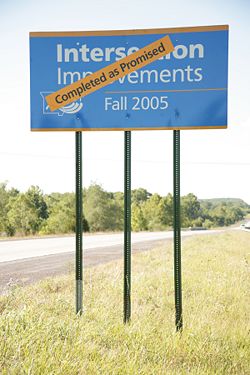
"Point of Presence" Sign. This sign is Commission furnished and is to be used on projects deemed prominent by the district. One sign should be placed in each direction of traffic on state highways. This sign is not to be used on roadways that are closed to traffic or where the construction has no effect on existing roadways. The “Point of Presence” sign is to be placed in a visible area within the project’s limits provided its placement does not disrupt a sequence of signs (e.g., between ROAD WORK AHEAD, RIGHT LANE CLOSED AHEAD and RIGHT LANE CLOSED). If a visible location within the project is not available, this sign may be placed approximately 500 ft. before the DRIVE SMART sign. Because of the sign’s width, flatter areas are preferable in order to avoid long post lengths in fill sections. The job estimate is to include the appropriate square footage of the sign as construction signing.
| POP sign guidance for ARRA projects |
 |
 |
The designer should complete the D-28 form and submit it to the Central Office Traffic Division where it will be detailed. The finished layout will be returned to the designer for inclusion in the traffic control plans.
The “POINT OF PRESENCE” sign is available in two sizes depending on roadway conditions. The 36 in. x 48 in. sign is used on low volume routes that carry 400 AADT or less, on projects that have a duration of 4 weeks or less or in urban areas where there is insufficient right of way for an eight foot wide sign. The 96 in. x 48 in. version of the sign is used in all other applications, but can also be used in place of the 36 in. x 48 in. sign if added emphasis is deemed necessary.
Appropriate pay items for the installation of this sign are to be included in the estimate and the cost of the sign is to be included in the job estimate as a non-contractual cost. The Resident Engineer will order the sign after the project schedule is received. Upon final inspection, district personnel will affix a "Completed As Promised" label to the sign in the specific location shown on the plans. District personnel are to remove the signs and sign posts approximately 90 days after the job has been accepted by MoDOT.

The options available to the designer to describe the project are listed below. Any deviations from this list must be approved by the Public Information and Outreach Unit.
- Bridge Improvements
- New Bridge
- Intersection Improvement
- Road Improvements
- Road Resurfacing
- New Signals
- New Intersection
- New Pavement
- Signal Improvements
- Pavement Repair
- Road Widening
- Safety Improvements
- Lane Additions
- New Interchange
- Surface Improvements
The options available for project completion date on the sign are Spring, Summer, Fall or Winter along with the year.
616.6.52 Advisory Speed Plaque (WO13-1P) (MUTCD 6F.52)

Option. In combination with a warning sign, an Advisory Speed (WO13-1P) plaque may be used to indicate a recommended speed around a curve or through a signed condition.
Standard. The Advisory Speed plaque shall not be used in conjunction with any sign other than a warning sign, nor shall it be used alone.
616.6.53 NEXT XX MILES Plaque (WO7-3aP) (MUTCD 6F.53)

Option. In combination with a warning sign, a NEXT XX MILES (WO7-3aP) plaque may be used to indicate the length of highway over which a work activity is being conducted, or over which a condition exists in the TTC zone. In long TTC zones, NEXT XX MILES plaques may be placed in combination with warning signs at regular intervals within the zone to indicate the remaining length of highway over which the TTC work activity or condition exists.
Standard. The NEXT XX MILES plaque shall not be used in conjunction with any sign other than a warning sign, nor shall it be used alone.
Guidance. When used in TTC zones, the NEXT XX MILES plaque should be placed below the initial warning sign designating that, within the approaching zone, a temporary work activity or condition exists.
616.6.54 Motorcycle Plaque (WO8-15P) (MUTCD6F.54)

Option. A Motorcycle (WO8-15P) plaque may be mounted below a GROOVED PAVEMENT (WO8-15) sign, if the warning is intended to be directed primarily to motorcyclists.
616.6.55 Guide Signs (MUTCD 6F.55)
Support. Guide signs along highways provide road users with information to help them along their way through the TTC zone. The design of guide signs is presented in EPG 903 Highway Signing.
Guidance. The following guide signs should be used in TTC zones as needed:
- A. Standard route markings, where temporary route changes are necessary,
- B. Directional signs and street name signs, and
- C. Special guide signs relating to the condition or work being done.
Standard. If additional temporary guide signs are used in TTC zones, they shall have a black legend and border on an MoDOT fluorescent orange background.
Option. Guide signs used in TTC incident management situations may have a black legend and border on a fluorescent pink background.
When directional signs and street name signs are used in conjunction with detour routing, these signs may have a black legend and border on an orange background.
When permanent directional signs or permanent street name signs are used in conjunction with detour signing, they may have a white legend on a green background.
616.6.56 ROAD WORK NEXT XX MILES Sign (GO20-1) (MUTCD 6F.56)

Guidance. The ROAD WORK NEXT XX MILES (GO20-1) sign should be installed in advance of TTC zones that are longer than 2 miles. The project with this sign may be a lane addition or have head-to-head lane reconstruction, for example. Examples of projects where this sign is not to be installed include new alignment, guardrail replacement, milling and paving or those with moving operations. The mileage on the road construction sign is rounded to the nearest mile.
Option. The ROAD WORK NEXT XX MILES sign may be mounted on a Type 3 Barricade. The sign may also be used for TTC zones of shorter length.
Standard. The distance displayed on the ROAD WORK NEXT XX MILES sign shall be stated to the nearest whole mile.
616.6.57 END ROAD WORK Sign (GO20-2) (MUTCD 6F.57)

Guidance. These signs shall be used when the ROAD WORK NEXT XX MILES sign is used.
Option. The END ROAD WORK sign may be installed on the back of a warning sign facing the opposite direction of road users or on the back of a Type 3 Barricade.
616.6.58 PILOT CAR FOLLOW ME (GO20-4) and PLEASE WAIT FOR PILOT CAR (SPECIAL) (MUTCD 6F.58)
Standard. The PILOT CAR FOLLOW ME (GO20-4) sign shall be mounted in a conspicuous position on the rear of a vehicle used for guiding one-way vehicular traffic through or around a TTC zone (see EPG 616.3.13).
Table 616.6.58
| Sign | Title | Sign No. | EPG Article | MUTCD section |
|---|---|---|---|---|
| PILOT CAR FOLLOW ME |
G20-4 | 616.6.58 | 6F.58 | |
| PLEASE WAIT FOR PILOT CAR |
SPECIAL | 616.6.58 | n/a |
616.6.59 Detour Signs (MO4-8, MO4-8a, MO4-8b, MO4-9, MO4-9a, MO4-9b, MO4-9c, and MO4-10) (MUTCD 6F.59)
Standard. Each detour shall be adequately marked with standard temporary route signs and destination signs.
Option. Detour signs in TTC incident management situations may have a black legend and border on a fluorescent pink background.
The Detour Arrow (M4-10) sign may be used where a detour route has been established.
The DETOUR (MO4-8) sign may be mounted at the top of a route sign assembly to mark a temporary route that detours from a highway, bypasses a section closed by a TTC zone, and rejoins the highway beyond the TTC zone.
Guidance. The Detour Arrow (MO4-10) sign should normally be mounted just below the ROAD CLOSED (R11-2, R11-3a, or R11-4) sign. The Detour Arrow sign should include a horizontal arrow pointed to the right or left as required. The DETOUR (MO4-9) sign (see Table 616.6.59) should be used for unnumbered highways, for emergency situations, for periods of short durations, or where, over relatively short distances, road users are guided along the detour and back to the desired highway without route signs.
A Street Name sign should be placed above, or the street name should be incorporated into, a DETOUR (M4-9) sign to indicate the name of the street being detoured.
Option. The END DETOUR (MO4-8a) or END (MO4-8b) sign may be used to indicate that the detour has ended.
Guidance. When the END DETOUR sign is used on a numbered highway, the sign should be mounted above a route sign after the downstream end of the detour.
The Pedestrian/Bicycle Detour (MO4-9a) sign should be used where a pedestrian/bicycle detour route has been established because of the closing of a pedestrian/bicycle facility to through traffic.
Standard. If used, the Pedestrian/Bicycle Detour sign shall have an arrow pointing in the appropriate direction.
Option. The arrow on a Pedestrian/Bicycle Detour sign may be on the sign face or on a supplemental plaque. The Pedestrian Detour (MO4-9b) sign or Bicycle Detour (MO4-9c) sign may be used where a pedestrian or bicycle detour route (not both) has been established because of the closing of the pedestrian or bicycle facility to through traffic.
Table 616.6.59
| Sign | Title | Sign No. | EPG Article | MUTCD section |
|---|---|---|---|---|
| DETOUR | M4-8 | 616.3 | 6F.59 | |
| END DETOUR | M4-8A | 616.3 | 6F.59 | |
 |
DETOUR | M4-9 | 616.3 | 6F.59 |
| BIKE/ PEDESTRIAN DETOUR | M4-9a | 616.3 | 6F.59 | |
| PEDESTRIAN DETOUR | M4-9b | 616.3 | 6F.59 | |
| BIKE DETOUR | M4-9c | 616.3 | 6F.59 | |
| DETOUR | M4-10 | 616.3 | 6F.59 |
616.6.60 Portable Changeable Message Signs (MUTCD 6F.60)
Support. Portable changeable message signs (PCMS) are TTC devices installed for temporary use with the flexibility to display a variety of messages. In most cases, portable changeable message signs follow the same provisions for design and application as those given for changeable message signs in EPG 910.3 Dynamic Message Signs. The information in this article describes situations where the provisions for changeable message signs differ from those given in EPG 910.3.
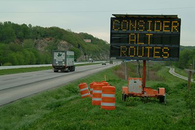
Portable changeable message signs are used most frequently on high-density urban freeways, but have applications on all types of highways where highway alignment, road user routing problems, or other pertinent conditions require advance warning and information.
Portable changeable message signs have a wide variety of applications in TTC zones including: roadway, lane, or ramp closures; incident management; width restriction information; speed control or reductions; advisories on work scheduling; road user management and diversion; warning of adverse conditions or special events; and other operational control.
The primary purpose of portable changeable message signs in TTC zones is to advise the road user of unexpected situations. Portable changeable message signs are particularly useful as they are capable of:
- A. Conveying complex messages,
- B. Displaying real time information about conditions ahead, and
- C. Providing information to assist road users in making decisions prior to the point where actions must be taken.
Some typical applications include the following:
| Related Information |
| Dynamic Message Signs (DMS) |
- A. Where the speed of vehicular traffic is expected to drop substantially;
- B. Where significant queuing and delays are expected;
- C. Where adverse environmental conditions are present;
- D. Where there are changes in alignment or surface conditions;
- E. Where advance notice of ramp, lane, or roadway closures is needed;
- F. Where crash or incident management is needed; and/or
- G. Where changes in the road user pattern occur.
Guidance. The components of a portable changeable message sign should include: a message sign, control systems, a power source, and mounting and transporting equipment. The front face of the sign should be covered with a protective material. CMSs shall not be used to replace or repeat static sign messages. Changeable message signs shall not display advertising.
Standard. Portable changeable message signs shall comply with the applicable design and application principles established in EPG 903 Highway Signing. Portable changeable message signs shall display only traffic operational, regulatory, warning, and guidance information, and shall not be used for advertising messages.
Support. EPG 910.3 Dynamic Message Signs contains information regarding overly simplistic or vague messages that is also applicable to portable changeable message signs.
Standard. The colors used for legends on portable changeable message signs shall comply with those shown in EPG 903.2 Extent of Signing.
Support. EPG 910.3 Dynamic Message Signs contains information regarding the luminance, luminance contrast, and contrast orientation that is also applicable to portable changeable message signs.
Guidance. Portable changeable message signs should be visible from 1/2 mile under both day and night conditions. Support:
EPG 903.5.7 SPEED LIMIT contains information regarding the design of portable changeable message signs that are used to display speed limits that change based on operational conditions, or are used to display the speed at which approaching drivers are traveling.
Guidance. A portable changeable message sign should be limited to three lines of eight characters per line or should consist of a full matrix display.
The letter height used for portable changeable message sign messages should be a minimum of 18 in. (see Standard Drawing 616.10).
Option. The changeable message sign may vary in size.
Guidance. Messages on a changeable message sign should consist of no more than two phases, and a phase should consist of no more than three lines of text. Each phase should be capable of being understood by itself, regardless of the order in which it is read. Messages should be centered within each line of legend. If more than one portable changeable message sign is simultaneously legible to road users, then only one of the signs should display a sequential message at any given time.
Support. Road users have difficulties in reading messages displayed in more than two phases on a typical three-line changeable message sign.
Standard. Techniques of message display such as animation, rapid flashing, dissolving, exploding, scrolling, travelling horizontally or vertically across the face of the sign, or other dynamic elements shall not be used.
Guidance. When a message is divided into two phases, the display time for each phase should be at least 2 seconds, and the sum of the display times for both of the phases should be a maximum of 8 seconds.
All messages should be designed with consideration given to the principles provided in this Section and also taking into account the following:
- A. The message should be as brief as possible and should contain three thoughts (with each thought preferably shown on its own line) that convey:
- 1. The problem or situation that the road user will encounter ahead,
- 2. The location of or distance to the problem or situation, and
- 3. The recommended driver action.
- B. If more than two phases are needed to display a message, additional changeable message signs should be used. When multiple changeable message signs are needed, they should be placed on the same side of the roadway and they should be separated from each other by a distance of at least 1,000 feet.
Standard. When the word messages need to be abbreviated on a changeable message sign, the provisions described in EPG 910.3 shall be followed.
In order to maintain legibility, changeable message signs shall automatically adjust their brightness under varying light conditions.
The control system shall include a display screen upon which messages can be reviewed before being displayed on the message sign. The control system shall be capable of maintaining memory when power is unavailable.
Changeable message signs shall be equipped with a power source and a battery back-up to provide continuous operation when failure of the primary power source occurs.
The mounting of changeable message signs on a trailer shall be such that the bottom of the message sign shall be a minimum of 7 ft. above the roadway when it is in the operating mode.
Guidance. Changeable message signs should be used as a supplement to and not as a substitute for conventional signs and pavement markings.
When changeable message signs are used for route diversion, they should be placed far enough in advance of the diversion to allow road users ample opportunity to perform necessary lane changes, to adjust their speed, or to exit the affected highway.
Changeable message signs should be sited and aligned to provide maximum legibility and to allow time for road users to respond appropriately to the portable changeable Message sign message.
Changeable message signs should be placed off the shoulder of the roadway and behind a traffic barrier, if practical. Where a traffic barrier is not available to shield the changeable message sign, it should be placed off the shoulder and outside of the clear zone. If a changeable message sign has to be placed on the shoulder of the roadway or within the clear zone, it should be delineated with retroreflective TTC devices (see Standard Drawing 616.10).
When changeable message signs are not being used to display TTC messages, they should be relocated such that they are outside of the clear zone or shielded behind a traffic barrier and turned away from traffic. If relocation or shielding is not practical, they should be delineated with retroreflective TTC devices.
Changeable message sign trailers should be delineated on a permanent basis by affixing retroreflective material, known as conspicuity material, in a continuous line on the face of the trailer as seen by oncoming road users.
616.6.61 Arrow Boards (MUTCD 6F.61)
Standard. An arrow board shall be a sign with a matrix of elements capable of either flashing or sequential displays. This sign shall provide additional warning and directional information to assist in merging and controlling road users through or around a TTC zone (see Standard Drawing 616.10).
Guidance. An arrow board in the arrow mode should be used to advise approaching traffic of a lane closure along major multi-lane roadways in situations involving heavy traffic volumes, high speeds, and/or limited sight distances, or at other locations and under other conditions where road users are less likely to expect such lane closures. If used, an arrow board should be used in combination with appropriate signs, channelizing devices, or other TTC devices.
An arrow board should be placed on the shoulder of the roadway or, if practical, farther from the traveled lane. It should be delineated with retroreflective TTC devices. When an arrow board is not being used, it should be removed; if not removed, it should be shielded; or if the previous two options are not feasible, it should be delineated with retroreflective TTC devices.
Flashing arrow panels are only to be used on multilane facilities. Flashing arrow panels are placed on the shoulder at the start of the taper for lane closures.
Flashing arrow panels are not used with temporary one-lane, two-way operations. Flashing arrow panels are not used to laterally shift one or more lanes of traffic through a temporary bypass or connection. Flashing arrow panels are not used to delineate narrow lanes, islands or fixed objects.
Quantities for flashing arrow panels are estimated and are tabulated on the plans.
Standard. Arrow boards shall meet the minimum size, legibility distance, number of elements, and other specifications. The overall minimum dimensions of the panels are 60 in. wide x 30 in. high for truck-mounted units and 96 in. wide x 48 in. high for trailer-mounted units.
Support. Type B arrow boards are normally truck-mounted units and appropriate for mobile operations on roadways. Type C arrow boards are normally trailer-mounted and intended to be used on traffic control projects. Type D arrow boards are intended for use on MoDOT emergency response vehicles for emergency use until standard temporary traffic control devices are available.
| Arrow Board Type | Minimum Size | Minimum Legibility | Minimum Number of Elements |
|---|---|---|---|
| B | 60 in. X 30 in. | ¾ mile | 15 |
| C | 96 in. X 48 in. | 1 mile | 15 |
| D | None* | ½ mile | 12 |
| * Length of arrow equals 48 in., width of arrowhead equals 24 in. | |||
Standard. Type B, and C arrow boards shall have solid rectangular appearances. A Type D arrow board shall conform to the shape of the arrow.
All arrow boards shall be finished in non-reflective black. The arrow board shall be mounted on a vehicle, a trailer, or other suitable support.
Guidance. The minimum mounting height, measured vertically from the bottom of the board to the roadway below it or to the elevation of the near edge of the roadway, of an arrow board should be 7 ft., except on vehicle-mounted arrow boards, which should be as high as practical.
A vehicle-mounted arrow board should be provided with remote controls.
Standard. Arrow board elements shall be capable of at least a 50 percent dimming from full brilliance. The dimmed mode shall be used for nighttime operation of arrow boards.
Guidance. Full brilliance should be used for daytime operation of arrow boards.
Standard. The arrow board shall have suitable elements capable of the various operating modes. The color presented by the elements shall be yellow.
Guidance. If an arrow board consisting of a bulb matrix is used, the elements should be recess-mounted or equipped with an upper hood of not less than 180 degrees.
Standard. The minimum element on-time shall be 50 percent for the flashing mode, with equal intervals of 25 percent for each sequential phase. The flashing rate shall be not less than 25 or more than 40 flashes per minute. An arrow board shall have the following three mode selections:
- A. A Flashing Arrow mode;
- B. A flashing Double Arrow mode; and
- C. A flashing Caution mode.
| Sign Display | Operating Mode | Direction |
|---|---|---|
 |
Flashing Arrow | Merge Right |
 |
Flashing Arrow | Merge Left |
 |
Flashing Double Arrow | Merge Right or Left |
 |
Flashing Caution | Non-directional |
An arrow board in the arrow mode shall be used only for stationary or moving lane closures on multi-lane roadways. For shoulder work, blocking the shoulder, for roadside work near the shoulder, or for temporarily closing one lane on a two-lane, two-way roadway, an arrow board shall be used only in the caution mode.
Guidance. For a stationary lane closure, the arrow board should be located on the shoulder at the beginning of the merging taper.
Where the shoulder is narrow, the arrow board should be located in the closed lane.
Standard. When arrow boards are used to close multiple lanes, a separate arrow board shall be used for each closed lane.
Guidance. When arrow boards are used to close multiple lanes, if the first arrow board is placed on the shoulder, the second arrow board should be placed in the first closed lane at the upstream end of the second merging taper Fig. 616.8.37 - MT. When the first arrow board is placed in the first closed lane, the second arrow board should be placed in the second closed lane at the downstream end of the second merging taper.
For mobile operations where a lane is closed, the arrow board should be located to provide adequate separation from the work operation to allow for appropriate reaction by approaching drivers.
Standard. A vehicle displaying an arrow board shall be equipped with high-intensity rotating, flashing, oscillating or strobe lights.
Arrow boards shall only be used to indicate a lane closure. Arrow boards shall not be used to indicate a lane shift.
Option. A portable changeable message sign may be used to simulate an arrow board display.
616.6.62 High-Level Warning Devices (Flag Trees) (MUTCD 6F.62)
MoDOT does not use the High-Level Warning Devices.
616.6.63 Channelizing Devices (MUTCD 6F.63)
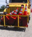 |
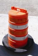 |
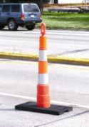 |
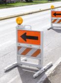 |
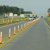 |
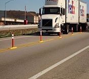 |
Standard. Designs of various channelizing devices shall be as shown in Standard Drawing 616.10. All channelizing devices shall be crashworthy.
Support. The function of channelizing devices is to warn road users of conditions created by work activities in or near the roadway and to guide road users. Channelizing devices include cones, tubular markers, vertical panels, drums, barricades and longitudinal channelizing devices.
Channelizing devices provide for smooth and gradual vehicular traffic flow from one lane to another, onto a bypass or detour, or into a narrower traveled way. They are also used to channelize vehicular traffic away from the work space, pavement drop-offs, pedestrian or shared-use paths, or opposing directions of vehicular traffic.
Standard. Devices used to channelize pedestrians shall be detectable to users of long canes and visible to persons having low vision.
Where channelizing devices are used to channelize pedestrians, there shall be continuous detectable bottom and top surfaces to be detectable to users of long canes. The bottom of the bottom surface shall be no higher than 2 in. above the ground. The top of the top surface shall be no lower than 32 in. above the ground.
Option. A gap not exceeding 2 in. between the bottom rail and the ground surface may be used to facilitate drainage.
Guidance. Where multiple channelizing devices are aligned to form a continuous pedestrian channelizer, connection points should be smooth to optimize long-cane and hand trailing.
Guidance for spacing between channelizers is located in EPG 616.3 Temporary Traffic Control Elements.
Option. Warning lights (see EPG 616.6.83 Warning Lights) may be added to channelizing devices in areas with frequent fog, snow, severe roadway curvature or where visual distractions are present.
Standard. Warning lights shall flash when placed on channelizing devices used alone or in a cluster to warn of a condition. Except for the sequential flashing warning lights, warning lights placed on channelizing devices used in a series to channelize road users shall be steady-burn.
Option. A series of sequential flashing warning lights may be placed on channelizing devices that form a merging taper in order to increase driver detection and recognition of the merging taper.
Standard. When used, the successive flashing of the sequential warning lights shall occur from the upstream end of the merging taper to the downstream end of the merging taper in order to identify the desired vehicle path. Each warning light in the sequence shall be flashed at a rate of not less than 55 nor more than 75 times per minute. The retro reflective material used on channelizing devices shall have a smooth, sealed outer surface that will display a similar color day or night.
Option. The name and telephone number of the highway agency, contractor, or supplier may be displayed on the non-retroreflective surface of all types of channelizing devices.
Standard. The letters and numbers of the name and telephone number shall be non-retroreflective and not over 2 in. tall.
Guidance. Particular attention should be given to maintaining the channelizing devices to keep them clean, visible, and properly positioned at all times.
Standard. Devices that are damaged or have lost a significant amount of their retroreflectivity and effectiveness shall be replaced.
616.6.64 Cones and Trim-lines (MUTCD 6F.64)
616.6.64.1 Cones
Standard. Cones (see Standard Drawing 616.10) shall be predominantly orange and shall be made of a material that can be struck without causing damage to the impacting vehicle.
Option. For temporary traffic control, cones may be used in lieu of trim-line channelizers for daytime operations on minor roads only and shall be a minimum of 28 inches in height. When specified, quantities are calculated and shown on the plans.
Traffic cones may be used to channelize road users, divide opposing vehicular traffic lanes, divide lanes when two or more lanes are kept open in the same direction, and delineate short duration maintenance and utility work.
Guidance. Steps should be taken to minimize the possibility of cones being blown over or displaced by wind or moving vehicular traffic.
Option. Cones may be doubled up to increase their weight.
Support. Some cones are constructed with bases that can be filled with ballast. Others have specially weighted bases, or weight such as sandbag rings that can be dropped over the cones and onto the base to provide added stability.
Guidance. Ballast should be kept to the minimum amount needed.
616.6.64.2 Trim-lines
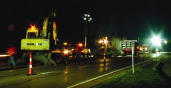
Standard. Trim-line channelizers (see Standard Drawing 616.10) shall be predominantly orange and shall be made of a material that can be struck without causing damage to the impacting vehicle. Retroreflectorization of trim-lines that are more than 42 in. tall shall be provided by horizontal, circumferential, alternating MoDOT fluorescent orange and MoDOT Type 3 white retroreflective stripes that are 4 in. to 6 in. wide. Each trim-line shall have a minimum of two orange and two white stripes with the top stripe being orange. Any non-retroreflective spaces between the orange and white stripes shall not be wider than 3 inches.
Guidance. Trim-line channelizers are the preferred channelizing devices used in work zones and are to be specified in ramp areas, intersections and areas with limited lateral clearances. Trim-line channelizers may be used in daytime or nighttime operations. When specified, quantities are calculated and shown on the plans.
Option. Trim-line may be used to channelize road users, divide opposing vehicular traffic lanes, divide lanes when two or more lanes are kept open in the same direction, and delineate short duration maintenance and utility work.
Guidance. Steps should be taken to minimize the possibility of cones being blown over or displaced by wind or moving vehicular traffic.
Support. Some cones are constructed with bases that can be filled with ballast. Others have specially weighted bases, or weight such as sandbag rings that can be dropped over the cones and onto the base to provide added stability.
Guidance. Ballast should be kept to the minimum amount needed.
616.6.65 Tubular Markers (MUTCD 6F.65)
Tubular markers typically divide traffic in temporary two-lane, two-way traffic situations as shown in Standard Drawing 616.10. When specified, quantities are calculated and shown on the plans.
Standard. Tubular markers shall be nominally 28 in. tall. They shall be made of a material that can be struck without causing damage to the impacting vehicle.
Tubular markers shall be retroreflectorized. Retroreflectorization of tubular markers shall be provided by two 3 in. wide MoDOT Type 3 or 5 white bands placed a maximum of 2 in. from the top with a maximum of 6 in. between the bands.
Guidance. Tubular markers should be stabilized by affixing them to the pavement, by using weighted bases, or weights such as sandbag rings that can be dropped over the tubular markers and onto the base to provide added stability. Ballast should be kept to the minimum amount needed.
Option. Tubular markers may be used effectively to divide opposing lanes of road users, and divide vehicular traffic lanes when two or more lanes of moving vehicular traffic are kept open in the same direction.
Standard. A tubular marker shall be attached to the pavement to display the minimum 2 in. width to the approaching road users.
616.6.66 Vertical Panels (MUTCD 6F.66)
Standard.' Vertical panels may be specified instead of trim-line channelizers for longitudinal channelization within the activity area. The diagonal marking provided by these devices subliminally directs motorists into the traffic space. This effect is beneficial in two-way two-lane operations and work zones within expressways and/or urban areas having many entrances. When specified, quantities are calculated and shown on the plans.
Vertical panels (see Standard Drawing 616.10) shall have retroreflective striped material that is 8 in. to 12 in. wide and at least 24 in. tall. They shall have alternating diagonal MoDOT fluorescent orange and MoDOT Type 3 white retroreflective stripes sloping downward at an angle of 45 degrees in the direction vehicular traffic is to pass.
Where the height of the retroreflective material on the vertical panel is 36 in., a stripe 6 in. wide shall be used.
Option. Where the height of the retroreflective material on the vertical panel is less than 36 in., a stripe 4 in. wide may be used.
Where space is limited, vertical panels may be used to channelize vehicular traffic, divide opposing lanes, or replace barricades.
616.6.67 Drums (MUTCD 6F.67)
Standard. Drums used for road user warning or channelization shall be constructed of lightweight, deformable materials. They shall be a minimum of 36 in. tall and have at least an 18 in. minimum width regardless of orientation. Metal drums shall not be used. The markings on drums shall be horizontal, circumferential, alternating MoDOT Type 3 orange and MoDOT type 3 white retroreflective stripes 4 in. to 6 in. wide. Each drum shall have a minimum of two orange and two white stripes with the top stripe being orange. Any non-retroreflectorized spaces between the horizontal orange and white stripes shall not exceed 3 inches wide. Drums shall have closed tops that will not allow collection of construction debris or other debris. (see Standard Drawing 616.10).
Support. Drums are highly visible, have good target value, give the appearance of being formidable obstacles and, therefore, command the respect of road users. They are portable enough to be shifted from place to place within a TTC zone in order to accommodate changing conditions, but are generally used in situations where they will remain in place for a prolonged period of time. Drum-like channelizers may be specified in lieu of trim-line channelizers to provide longitudinal channelization within the activity area if their larger size and additional retroreflective area are deemed appropriate.
Option. Although drums are most commonly used to channelize or delineate road user flow, they may also be used alone or in groups to mark specific locations.
Guidance. Drums should not be weighted with sand, water, or any material to the extent that would make them hazardous to road users or workers when struck. Drums used in regions susceptible to freezing should have drain holes in the bottom so that water will not accumulate and freeze causing a hazard if struck by a road user. Drum-like channelizers are not to be used in ramp areas, intersections or areas with limited lateral clearance.
Standard. Ballast shall not be placed on the top of a drum.
616.6.68 Type 1 or 3 Barricades (MUTCD 6F.68)
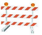 |
 |
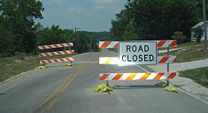 |
Support. A barricade is a portable or fixed device having from one to three rails with appropriate markings and is used to control road users by closing, restricting, or delineating all or a portion of the right of way. (See Standard Drawing 616.10).
For MoDOT use, barricades are classified as Type 1 or Type 3.
Standard. Stripes on barricade rails shall be alternating orange and white retroreflective stripes sloping downward at an angle of 45 degrees in the direction road users are to pass. Except as provided in the below option, the stripes shall be 6 in. wide.
Option. When rail lengths are less than 36 in., 4 in. wide stripes may be used.
Standard. The minimum length for Type 1 Barricades shall be 24 in., and the minimum length for Type 3 Barricades shall be 48 inches. Each barricade rail shall be 8 in. to 12 in. wide. Barricades used on freeways, expressways, and other high-speed roadways shall have a minimum of 270 square inches of retroreflective area facing road users.
Guidance. Where barricades extend entirely across a roadway, the stripes should slope downward in the direction toward which road users must turn.
Where both right and left turns are provided, the barricade stripes should slope downward in both directions from the center of the barricade or barricades.
Where no turns are intended, the stripes should be positioned to slope downward toward the center of the barricade or barricades.
Barricade rails should be supported in a manner that will allow them to be seen by the road user, and in a manner that provides a stable support that is not easily blown over or displaced.
The width of the existing pedestrian facility should be provided for the temporary facility if practical. Traffic control devices and other construction materials and features should not intrude into the usable width of the sidewalk, temporary pathway, or other pedestrian facility. When it is not possible to maintain a minimum width of 60 in. throughout the entire length of the pedestrian pathway, a 60 in. x 60 in. passing space should be provided at least every 200 ft. to allow individuals in wheelchairs to pass.
Barricade rail supports should not project into pedestrian circulation routes more than 4 in. from the support between 27 in. and 80 in. from the surface as described in Section 4.4.1 of the “Americans with Disabilities Act Accessibility Guidelines for Buildings and Facilities (ADAAG)” (see EPG 900.1.11).
Option. For Type 1 Barricades, the support may include other unstriped horizontal rails necessary to provide stability.
Guidance. On high-speed expressways or in other situations where barricades may be susceptible to overturning in the wind, ballasting should be used.
Option. Sandbags may be placed on the lower parts of the frame or the stays of barricades to provide the required ballast.
Support. The Type I (one rail) barricade is only acceptable for use in non-motorized traffic operations on all highways and in emergency road closures on two-lane, undivided highways.
Option. Barricades may be used alone or in groups to mark a specific condition or they may be used in a series for channelizing road users.
Guidance. Type 3 Barricades should be used on freeways and expressways or other high-speed roadways. Type 3 Barricades should be used to close or partially close a road.
Option. One Type 3 Barricade shall be used to completely close each 8 ft. of pavement. Paved shoulders shall be included in the area to be closed.
Guidance. Where provision is made for access of authorized equipment and vehicles, the responsibility for Type 3 Barricades should be assigned to a person who will provide proper closure at the end of each work day.
Support. When a highway is legally closed but access must still be allowed for local road users, barricades usually are not extended completely across the roadway.
Standard. A sign shall be installed with the appropriate legend concerning permissible use by local road users (see Standard Drawing 616.10). Adequate visibility of the barricades from both directions shall be provided.
Option. Signs may be installed on barricades (see Standard Drawing 616.10).
616.6.68.1 Design and Construction Details
Type III Movable Barricade details are shown in Standard Drawing 616.10. When Type III Movable Barricades are used, appropriate signing is provided. Type C warning lights may also be specified where additional impact is deemed appropriate. Sign and warning light mounting methods are not to be specified since this is left to the contractor's preference. Refer to the figures in all of the EPG 616 Temporary Traffic Control articles and EPG 616.3.6.1 Workspace for additional guidance.
One barricade is required for every 8 ft. of pavement, so a typical roadway with two 12 ft. lanes and two 4 ft. shoulders will require four barricades. The plans are to indicate the number and locations of barricades, signs and warning lights. When specified, quantities for barricades and barricades with warning lights are calculated and shown on the plans. The quantity of signs needed for barricades shall be paid for as construction signs.
616.6.68.2 Maintenance Details
Maintenance forces may refer to the above details for signs and warning lights when deemed appropriate.
616.6.69 Direction Indicator Barricades (MUTCD 6F.69)
Standard. The Direction Indicator Barricade shall consist of a One-Direction Large Arrow (WO1-6) sign mounted above a diagonal striped, horizontally aligned, retroreflective rail.
The One-Direction Large Arrow (WO1-6) sign shall be black on an MoDOT Fluorescentorange background. The stripes on the bottom rail shall be alternating MoDOT Fluorescent orange and MoDOT Type 3 white retroreflective stripes sloping downward at an angle of 45 degrees in the direction road users are to pass. The stripes shall be 4 in. wide. The One-Direction Large Arrow (WO1-6) sign shall be 24 in. x 12 inches. The bottom rail shall be 24 in. long and 8 in. tall (see Standard Drawing 616.10). For long-term stationary operations, direction indicator barricades (DIBs) should be used instead of trim-lime channelizers in merging tapers because they provide direction and have a larger target area for the motorists.
Option. For shorter duration projects, DIBs may be used in lieu of other channelizers. DIBs are not to be specified in shifting tapers except for the shifting tapers shown on Sheet 4 of Lane Closure, Fig. 616.0.2. When specified, quantities are calculated and shown on the plans.
616.6.70 Temporary Traffic Barriers as Channelizing Devices (MUTCD 6F.70)
Support. Temporary traffic barriers are not TTC devices in themselves; however, when placed in a position identical to a line of channelizing devices and marked and/or equipped with appropriate channelization features to provide guidance and warning both day and night, they serve as TTC devices (see EPG 617.1 Temporary Traffic Barriers).
Standard. Temporary traffic barriers serving as TTC devices shall comply with requirements for such devices as set forth throughout EPG 616.
Temporary traffic barriers (see EPG 616.6.85 Temporary Traffic Barriers) shall not be used solely to channelize road users, but also to protect the work space. If used to channelize vehicular traffic, the temporary traffic barrier shall be supplemented with delineation, pavement markings, or channelizing devices for improved daytime and nighttime visibility.
Guidance. Temporary traffic barriers should not be used for a merging taper except in low-speed urban areas. When it is necessary to use a temporary traffic barrier for a merging taper in low-speed urban areas or for a constricted/restricted TTC zone, the taper length should be designed to optimize road user operations considering the available geometric conditions.
Standard. When it is necessary to use a temporary traffic barrier for a merging taper in low-speed urban areas or for a constricted/restricted TTC zone, the taper shall be delineated.
Guidance. When used for channelization, temporary traffic barriers should be of a light color for increased visibility.
616.6.71 Longitudinal Channelizing Devices (MUTCD 6F.71)
MoDOT has not approved the use of Longitudinal Channelizing Devices.
616.6.72 Temporary Lane Separators (MUTCD 6F.72)
MoDOT has not approved the use of Temporary Lane Separators.
616.6.73 Other Channelizing Devices (MUTCD 6F.73)
Option. Channelizing devices other than those described in MODOT Standard Drawing 616.10 may not be used.
616.6.74 Detectable Edging for Pedestrians (MUTCD 6F.74)
Support. Individual channelizing devices, tape or rope used to connect individual devices, other discontinuous barriers and devices, and pavement markings are not detectable by persons with visual disabilities and are incapable of providing detectable path guidance on temporary or realigned sidewalks or other pedestrian facilities.
Guidance. When it is determined that a facility should be accessible to and detectable by pedestrians with visual disabilities, a continuously detectable edging should be provided throughout the length of the facility such that it can be followed by pedestrians using long canes for guidance. This edging should protrude at least 6 in. above the surface of the sidewalk or pathway, with the bottom of the edging a maximum of 2.5 in. above the surface. This edging should be continuous throughout the length of the facility except for gaps at locations where pedestrians or vehicles will be turning or crossing. This edging should consist of a prefabricated or formed-in-place curbing or other continuous device that is placed along the edge of the sidewalk or walkway. This edging should be firmly attached to the ground or to other devices. Adjacent sections of this edging should be interconnected such that the edging is not displaced by pedestrian or vehicular traffic or work operations, and such that it does not constitute a hazard to pedestrians, workers, or other road users.
Support. Examples of detectable edging for pedestrians include:
- A. Prefabricated lightweight sections of plastic, metal, or other suitable materials that are interconnected and fixed in place to form a continuous edge.
- B. Prefabricated lightweight sections of plastic, metal, or other suitable materials that are interconnected, fixed in place, and placed at ground level to provide a continuous connection between channelizing devices located at intervals along the edge of the sidewalk or walkway.
- C. Sections of lumber interconnected and fixed in place to form a continuous edge.
- D. Formed-in-place asphalt or concrete curb.
- E. Prefabricated concrete curb sections that are interconnected and fixed in place to form a continuous edge.
- F. Continuous temporary traffic barrier or longitudinal channelizing barricades placed along the edge of the sidewalk or walkway that provides a pedestrian edging at ground level.
- G. Chain link or other fencing equipped with a continuous bottom rail.
Guidance. Detectable pedestrian edging should be orange, white, or yellow and should match the color of the adjacent channelizing devices or traffic control devices, if any are present.
616.6.75 Temporary Raised Islands (MUTCD 6F.75)
Standard. Temporary raised islands shall be used only in combination with pavement striping and other suitable channelizing devices.
Option. A temporary raised island may be used to separate vehicular traffic flows in two-lane, two-way operations on roadways having a vehicular traffic volume range of 4,000 to 15,000 average daily traffic (ADT) and on freeways having a vehicular traffic volume range of 22,000 ADT to 60,000 ADT.
Temporary raised islands also may be used in other than two-lane, two-way operations where physical separation of vehicular traffic from the TTC zone is not required.
Guidance. Temporary raised islands should have the basic dimensions of 4 in. tall by at least 12 in. wide and have rounded or chamfered corners.
The temporary raised islands should not be designed in such a manner that they would cause a motorist to lose control of the vehicle if the vehicle inadvertently strikes the temporary raised island. If struck, pieces of the island should not be dislodged to the extent that they could penetrate the occupant compartment or involve other vehicles.
Standard. At pedestrian crossing locations, temporary raised islands shall have an opening or be shortened to provide at least a 60 in. wide pathway for the crossing pedestrian.
616.6.76 Opposing Traffic Lane Divider and Sign (W6-4) (MUTCD 6F.76)
MoDOT does not use Opposing Traffic Lane dividers.
616.6.77 Pavement Markings (MUTCD 6F.77)
Support. Pavement markings are installed or existing markings are maintained or enhanced in TTC zones to provide road users with a clearly defined path for travel through the TTC zone in day, night, and twilight periods under both wet and dry pavement conditions.
Guidance. The work should be planned and staged to provide for the placement and removal of the pavement markings in a way that minimizes the disruption to traffic flow approaching and through the TTC zone during the placement and removal process.
Standard. Existing pavement markings shall be maintained in all long-term stationary (see EPG 616.6.2) TTC zones in accordance with EPG 620.1 General and EPG 620.2 Pavement and Curb Marking, except as otherwise provided for temporary pavement markings in EPG 616.6.78. Pavement markings shall match the alignment of the markings in place at both ends of the TTC zone. Pavement markings shall be placed along the entire length of any paved detour or temporary roadway prior to the detour or roadway being opened to road users.
For long-term stationary operations, pavement markings in the temporary traveled way that are no longer applicable shall be removed or obliterated as soon as practical. Pavement marking obliteration shall remove the non-applicable pavement marking material, and the obliteration method shall minimize pavement scarring. Painting over existing pavement markings with black paint or spraying with asphalt shall not be accepted as a substitute for removal or obliteration.
Option. Removable, non-reflective, preformed tape that is approximately the same color as the pavement surface may be used where markings need to be covered temporarily.
616.6.78 Temporary Markings (MUTCD 6F.78)
Support. Temporary markings are those pavement markings or devices that are placed within TTC zones to provide road users with a clearly defined path of travel through the TTC zone when the permanent markings are either removed or obliterated during the work activities. Temporary markings are typically needed during the reconstruction of a road while it is open to traffic, such as overlays or surface treatments or where lanes are temporarily shifted on pavement that is to remain in place. Preformed removable marking tape is the preferred temporary pavement marking material on final wearing surfaces.
Guidance. Unless justified based on engineering judgment, temporary pavement markings should not remain in place for more than 14 days after the application of the pavement surface treatment or the construction of the final pavement surface on new roadways or over existing pavements.
The temporary use of edge lines, channelizing lines, lane-reduction transitions, gore markings, and other longitudinal markings, and the various non-longitudinal markings (such as stop lines, railroad crossings, crosswalks, words, symbols, or arrows) should be in accordance with Standard Plan 620.10 and EPG 620 Pavement Marking.
Short-term pavement marking tape is used in locations where the marking will be in place no more than two weeks. It is cost effective only in small quantities. Short-term pavement marking is not normally removed. If removal is required, removable tape is the preferred material.
Standard. Warning signs, channelizing devices, and delineation shall be used to indicate required road user paths in TTC zones where it is not possible to provide a clear path by pavement markings.
Except as otherwise provided in this Section, all temporary pavement markings for no-passing zones shall comply with the requirements of EPG 620.1 General and EPG 620.2 Pavement and Curb Markings. All temporary broken-line pavement markings shall use the same cycle length as permanent markings and shall have line segments that are at least 4 ft. long.
Guidance. All pavement markings and devices used to delineate road user paths should be reviewed during daytime and nighttime periods.
Option. MoDOT does not sign for passing zones. If used, the NO CENTER LINE sign should be placed in accordance with EPG 616.6.47.
616.6.79 Temporary Raised Pavement Markers (MUTCD 6F.79)
Option. Retroreflective or internally illuminated raised pavement markers, or non-retroreflective raised pavement markers supplemented by retroreflective or internally illuminated markers, may be substituted for markings of other types in TTC zones.
Standard. If used, the color and pattern of the raised pavement markers shall simulate the color and pattern of the markings for which they substitute.
The value of N for a broken or dotted line shall equal the length of one line segment plus one gap.
The value of N referenced for solid lines shall equal the N for the broken or dotted lines that might be adjacent to or might extend the solid lines (see EPG 620.2 Pavement and Curb Markings).
The spacing and locations of temporary pavement markers shall be in accordance with Standard Plan 620.00.
Option. Temporary marking tape may be used to establish experimental lanes or intersection markings to determine the markings effectiveness prior to installing the permanent markings. It may also be used to mark temporary centerlines following spot sealing and patching operations.
Temporary pavement marking may be used as a short term replacement for existing marking for grinding, milling and resurfacing, but no direct payment is made to the contractor as described in Sec 620.
Temporary raised pavement markers may be used to substitute for broken line segments by using at least two retroreflective markers placed at each end of a segment of 2 ft. to 5 ft. long, using the same cycle length as permanent markings.
Guidance. Temporary raised pavement markers used on 2 ft. to 5 ft. segments to substitute for broken line segments should not be in place for more than 14 days unless justified by engineering judgment.
Raised pavement markers should be considered for use along surfaced detours or temporary roadways, and other changed or new travel-lane alignments.
616.6.80 Delineators (MUTCD 6F.80)
MoDOT does not use delineators in work zones.
616.6.81 Lighting Devices (MUTCD 6F.81)
Guidance. Lighting devices should be provided in TTC zones based on engineering judgment.
When used to supplement channelization, the maximum spacing for warning lights should be identical to the channelizing device spacing requirements.
Option. Lighting devices may be used to supplement retroreflectorized signs, barriers, and channelizing devices. During normal daytime maintenance operations, the functions of flashing warning beacons may be provided by high-intensity rotating, flashing, oscillating, or strobe lights on a maintenance vehicle.
Standard. Although vehicle hazard warning lights are permitted to be used to supplement high-intensity rotating, flashing, oscillating or strobe lights, they shall not be used instead of high-intensity rotating, flashing, oscillating or strobe lights.
616.6.82 Floodlights (MUTCD 6F.82)
Support. Utility, maintenance, or construction activities on highways are frequently conducted during nighttime periods when vehicular traffic volumes are lower. Large construction projects are sometimes operated on a double-shift basis requiring night work (see EPG 616.6.19).
Guidance. When nighttime work is being performed, floodlights should be used to illuminate the work area, equipment crossings and other areas.
Standard. Except in emergency situations, flagger stations shall be illuminated at night.
Floodlighting shall not produce a disabling glare condition for approaching road users, flaggers, or workers.
Guidance. The adequacy of the floodlight placement and elimination of potential glare should be determined by driving through and observing the floodlighted area from each direction on all approaching roadways after the initial floodlight setup, at night and periodically.
Support. Desired illumination levels vary depending upon the nature of the task involved. An average horizontal luminance of 5 foot-candles can be adequate for general activities. Tasks requiring high levels of precision and extreme care can require an average horizontal luminance of 20 foot-candles.
Typical work zone lighting may include dirigible lighting, portable light towers, balloon lighting, lights attached to equipment or post-mounted lights. In some cases, existing lighting or ambient lighting may meet lighting level requirements and negate the need for including work zone lighting as a pay item.
When stationary operations exceed 15 consecutive days, such as a bridge replacement, interchange or intersection work that occurs at night, temporary fixed lighting is considered in lieu of work zone lighting. Temporary fixed lighting is also be considered for islands, temporary bypasses, crossovers and connections and areas of potential conflict, such as temporary ramps, intersections and one-lane, two-way traffic operations that are in place for more than 15 consecutive days. These conditions may require lighting even though the work may not be conducted at night. This type of lighting, while more difficult to design and install, provides more uniform light distribution thereby enabling the motorist to better navigate the work zone at night. If temporary fixed lighting is chosen, it must be designed, shown in the plans and a 901 pay item for “Temporary Lighting” included. Temporary fixed lighting generally includes wood poles, luminaires and power supplies. Refer to Sec 901 for lighting requirements and EPG 901 Lighting for lighting design.
Flagger stations in operation at night are required to be lit. Payment for this is generally included as part of the lump sum for either work zone lighting or temporary lighting.
616.6.83 Warning Lights (MUTCD 6F.83)
Support. Type A, Type B, and Type C warning lights are portable, powered, yellow, lens-directed, enclosed lights (see Standard Drawing 616.10).
The use of Type A and Type C warning lights is usually limited. Quantities for warning lights are calculated independently of the traffic control devices and are tabulated on the plans.
Standard. Warning lights shall be in accordance with the current ITE “Purchase Specification for Flashing and Steady-Burn Warning Lights” (see EPG 900.1.11).
When warning lights are used, they shall be mounted on signs or channelizing devices in a manner that, if hit by an errant vehicle, they will not be likely to penetrate the windshield.
Guidance. The maximum spacing for warning lights should be identical to the channelizing device spacing requirements.
Support. The light weight and portability of warning lights are advantages that make these devices useful as supplements to the retroreflectorization on signs and channelizing devices. The flashing lights are effective in attracting road users’ attention.
Option. Warning lights may be used in either a steady-burn or flashing mode.
Standard. Except for the sequential flashing warning lights, flashing warning lights shall not be used for delineation, as a series of flashers fails to identify the desired vehicle path.
Option. A series of sequential flashing warning lights may be placed on channelizing devices that form a merging taper in order to increase driver detection and recognition of the merging taper.
Standard. If a series of sequential flashing warning lights is used, the successive flashing of the lights shall occur from the upstream end of the merging taper to the downstream end of the merging taper in order to identify the desired vehicle path. Each flashing warning light in the sequence shall be flashed at a rate of not less than 55 or more than 75 times per minute.
Type A Low-Intensity Flashing warning lights, and Type C Steady-Burn warning lights shall be maintained so as to be capable of being visible on a clear night from a distance of 3,000 feet. Type B High-Intensity Flashing warning lights shall be maintained so as to be capable of being visible on a sunny day when viewed without the sun directly on or behind the device from a distance of 1,000 feet.
Warning lights shall have a minimum mounting height of 30 inches to the bottom of the lens.
Support. Type A Low-Intensity Flashing warning lights are used to warn road users during nighttime hours that they are approaching or proceeding in a potentially hazardous area. These flashing lights may be used on drum-like channelizers to warn of an unexpected, isolated hazard. This device is not used in shifts, tapers or long runs of channelizing devices.
Option. Type A warning lights may be mounted on channelizing devices.
Support. Type B High-Intensity Flashing warning lights are used to warn road users during both daylight and nighttime hours that they are approaching a potentially hazardous area. These flashing lights may be used on advanced warning signs when geometrics, traffic volumes or other conditions warrant increased visibility.
Option. Type B warning lights are designed to operate 24 hours per day and may be mounted on advance warning signs or on independent supports.
Type C Steady-Burn warning lights may be used during nighttime hours to delineate the edge of the traveled way. These steady burn lights may be used on drum-like channelizers to delineate traffic in shifts, tapers or long runs or on direction indicator barricades in merging tapers in the work area at night at the designer’s discretion.
Guidance. When used to delineate a curve, Type C warning lights should only be used on devices on the outside of the curve, and not on the inside of the curve.
616.6.84 Temporary Traffic Control Signals (MUTCD 6F.84)
Standard. Temporary traffic control signals (see EPG 902.5.44) used to control road user movements through TTC zones and in other TTC situations shall comply with the applicable provisions of EPG 902 Signals.
Support. Temporary traffic control signals are typically used in TTC zones such as temporary haul road crossings; temporary one-way operations along a one-lane, two-way highway; temporary one-way operations on bridges, reversible lanes and intersections.
Standard. A temporary traffic control signal that is used to control traffic through a one-lane, two-way section of roadway shall comply with the provisions of EPG 902.9.2.
Both of the following criteria are to be met for temporary signals:
- (1) the traffic volumes using the intersection during the detour period meet the volume or interruption signal warrants as described in EPG 902 Signals and
- (2) the intersection has sufficient geometrics for signalization.
Guidance. Where pedestrian traffic is detoured to a temporary traffic control signal, engineering judgment should be used to determine if pedestrian signals or accessible pedestrian signals (see EPG 902.6.9) are needed for crossing along an alternate route.
When temporary traffic control signals are used, conflict monitors typical of traditional traffic control signal operations should be used.
Option.Temporary traffic control signals may be portable or temporarily mounted on fixed supports.
Guidance. Temporary traffic control signals should only be used in situations where temporary traffic control signals are preferable to other means of traffic control, such as changing the work staging or work zone size to eliminate one-way vehicular traffic movements, using flaggers to control one-way or crossing movements, using STOP or YIELD signs, and using warning devices alone.
Due to construction detours through an intersection, temporary signals may be warranted at an intersection that is normally unsignalized. The detoured traffic may result from the closing of a ramp, interchange, intersection or route. The intersection affected by the detoured traffic may be in the work zone or project limits. Temporary signals are considered only when detours will be in effect for more than 15 consecutive days.
Support. Factors related to the design and application of temporary traffic control signals include the following:
- A. Safety and road user needs;
- B. Work staging and operations;
- C. The feasibility of using other TTC strategies (for example, flaggers, providing space for two lanes, or detouring road users, including bicyclists and pedestrians);
- D. Sight distance restrictions;
- E. Human factors considerations (for example, lack of driver familiarity with temporary traffic control signals);
- F. Road-user volumes including roadway and intersection capacity;
- G. Affected side streets and driveways;
- H. Vehicle speeds;
- I. The placement of other TTC devices;
- J. Parking;
- K. Turning restrictions;
- L. Pedestrians;
- M. The nature of adjacent land uses (such as residential or commercial);
- N. Legal authority;
- O. Signal phasing and timing requirements;
- P. Full-time or part-time operation;
- Q. Actuated, fixed-time, or manual operation;
- R. Power failures or other emergencies;
- S. Inspection and maintenance needs;
- T. Need for detailed placement, timing and operation records and
- U. Operation by contractors or by others.
Although temporary traffic control signals can be mounted on trailers or lightweight portable supports, fixed supports offer superior resistance to displacement or damage by severe weather, vehicle impact and vandalism.
Guidance. Other TTC devices should be used to supplement temporary traffic control signals, including warning and regulatory signs, pavement markings and channelizing devices.
Temporary traffic control signals not in use should be covered or removed.
If a temporary traffic control signal is located within 1/2 mile of an adjacent traffic control signal, consideration should be given to interconnected operation.
Standard. Temporary traffic control signals shall not be located within 200 ft. of a grade crossing unless the temporary traffic control signal is provided with preemption in accordance with EPG 902.5.38, or unless a uniformed officer or flagger is provided at the crossing to prevent vehicles from stopping within the crossing.
Wood pole span wire signals are used for temporary signals. The signal phasing, location and type of signal heads and signing are designed as described in EPG 902 Signals. Temporary lighting is provided on the signal poles (silhouette discernment lighting as described in EPG 901 Lighting). Temporary signals are normally pre-timed, although semi-actuated or fully-actuated control may be considered based on conditions. It is not necessary to itemize quantities, but a scaled layout is included in the TCP showing all items, proposed pole and signal controller locations and signal phasing.
616.6.85 Temporary Traffic Barriers (MUTCD 6F.85)
Support. Temporary traffic barriers, including shifting portable or movable barriers, are devices designed to help prevent penetration by vehicles while minimizing injuries to vehicle occupants and to protect workers, bicyclists and pedestrians.
The four primary functions of temporary traffic barriers are:
- A. To keep vehicular traffic from entering work areas, such as excavations or material storage sites;
- B. To separate workers, bicyclists, and pedestrians from motor vehicle traffic;
- C. To separate opposing directions of vehicular traffic; and
- D. To separate vehicular traffic, bicyclists, and pedestrians from the work area such as false work for bridges and other exposed objects.
Option. Temporary traffic barriers may be used to separate two-way vehicular traffic.
Guidance. Because the protective requirements of a TTC situation have priority in determining the need for temporary traffic barriers, their use should be based on an engineering study.
Standard. Temporary traffic barrier is required on roadway excavation edge drop-offs (refer to Standard Plan 619.10), bridge rehabilitation jobs with bridge rail replacement and/or full depth repair, and is to be considered for any other type of long-term bridge repair work. When specified, quantities are calculated and shown on the plans. Delineators for temporary concrete traffic barriers are provided at no direct pay as shown on Standard Plan 617.20 and stated in Sec 617. Delineator pay items are used only to retrofit existing permanent concrete traffic barrier.
Appropriate channelizing devices and pavement marking are always used in front of barrier tapers for lane closures, shoulder closures or transition areas for temporary bypasses or connections. Wherever practical, a lateral shy distance is to be provided between the edge of the driving lane and the barrier, and a longitudinal buffer area is to be provided between the channelizer taper and the barrier taper.
Temporary traffic barriers shall be supplemented with standard delineation, pavement markings, or channelizing devices for improved daytime and nighttime visibility if they are used to channelize vehicular traffic. The delineation color shall match the applicable pavement marking color.
Temporary traffic barriers, including their end treatments, shall be crashworthy. In order to mitigate the effect of striking the upstream end of a temporary traffic barrier, the end shall be installed in accordance with AASHTO’s Roadside Design Guide (see EPG 900.1.11) by flaring until the end is outside the acceptable clear zone or by providing crashworthy end treatments.
Option. Warning lights or steady-burn lamps may be mounted on temporary traffic barrier installations.
Support. Movable barriers are capable of being repositioned laterally using a transfer vehicle that travels along the barrier. Movable barriers enable short-term closures to be installed and removed on long-term projects. Providing a barrier-protected work space for short-term closures and providing unbalanced flow to accommodate changes in the direction of peak-period traffic flows are two of the advantages of using movable barriers.
MUTCD Figure 6H-45 shows a temporary reversible lane using movable barriers. The notable feature of the movable barrier is that in both Phase A and Phase B, the lanes used by opposing traffic are separated by a barrier.
Fig. 616.0.2 shows an exterior lane closure using a temporary traffic barrier. Notes 7 though 9 address the option of using a movable barrier. By using a movable barrier, the barrier can be positioned to close the lane during the off-peak periods and can be relocated to open the lane during peak periods to accommodate peak traffic flows. With one pass of the transfer vehicle, the barrier can be moved out of the lane and onto the shoulder. Furthermore, if so desired, with a second pass of the transfer vehicle, the barrier could be moved to the roadside beyond the shoulder.
More specific information on the use of temporary traffic barriers is contained in Chapters 8 and 9 of AASHTO’s Roadside Design Guide (see EPG 900.1.11).
616.6.86 Crash Cushions (MUTCD 6F.86)
Support. Crash cushions are systems that mitigate the effects of errant vehicles that strike obstacles, either by smoothly decelerating the vehicle to a stop when hit head-on, or by redirecting the errant vehicle. The two types of crash cushions that are used in TTC zones are stationary crash cushions and truck-mounted attenuators. Crash cushions in TTC zones help protect the drivers from the exposed ends of barriers, fixed objects, shadow vehicles, and other obstacles. Specific information on the use of crash cushions can be found in AASHTO’s Roadside Design Guide (see EPG 900.1.11, EPG 617.1 Temporary Traffic Barriers and EPG 612.1 Impact Attenuators).
Standard. Crash cushions shall be crashworthy. They shall also be designed for each application to stop or redirect errant vehicles under prescribed conditions. Crash cushions shall be periodically inspected to verify that they have not been hit or damaged. Damaged crash cushions shall be promptly repaired or replaced to maintain their crashworthiness.
Support. Stationary crash cushions are used in the same manner as permanent highway installations to protect drivers from the exposed ends of barriers, fixed objects and other obstacles.
Standard. An approved crash cushion is installed on the exposed end of the barrier where the posted speed prior to construction on an existing facility or the anticipated posted speed of a temporary facility is greater than 35 mph. A crash cushion will be required on the upstream end for divided facilities, and on both ends for all two-way facilities.
Stationary crash cushions shall be designed for the specific application intended.
Truck-mounted attenuators shall be energy-absorbing devices attached to the rear of shadow trailers or trucks. If used, the shadow vehicle with the attenuator shall be located in advance of the work area, workers or equipment to reduce the severity of rear-end crashes from errant vehicles.
Support. Trucks or trailers are often used as shadow vehicles to protect workers or work equipment from errant vehicles. These shadow vehicles are normally equipped with flashing arrows, changeable message signs, and/or high-intensity rotating, flashing, oscillating or strobe lights located properly in advance of the workers and/or equipment that they are protecting. However, these shadow vehicles might themselves cause injuries to occupants of the errant vehicles if they are not equipped with truck-mounted attenuators.
Guidance. The shadow truck should be positioned a sufficient distance in advance of the workers or equipment being protected so that there will be sufficient distance, but not so much so that errant vehicles will travel around the shadow truck and strike the protected workers and/or equipment.
Support. Chapter 9 of AASHTO’s Roadside Design Guide (see EPG 900.1.11) contains additional information regarding the use of shadow vehicles.
Guidance. If used, the truck-mounted attenuator should be used in accordance with the manufacturer’s specifications.
616.6.87 Rumble Strips (MUTCD 6F.87)
Support. Transverse rumble strips consist of intermittent, narrow, transverse areas of rough-textured or slightly raised or depressed road surface that extend across the travel lanes to alert drivers to unusual vehicular traffic conditions. Through noise and vibration they attract the driver’s attention to such features as unexpected changes in alignment and to conditions requiring a stop.
Longitudinal rumble strips consist of a series of rough-textured or slightly raised or depressed road surfaces located along the shoulder to alert road users that they are leaving the travel lanes.
Standard. If it is desirable to use a color other than the color of the pavement for a longitudinal rumble strip, the color of the rumble strip shall be the same color as the longitudinal line the rumble strip supplements.
If the color of a transverse rumble strip used within a travel lane is not the color of the pavement, the color of the rumble strip shall be white, black, or orange.
Option. Intervals between transverse rumble strips may be reduced as the distance to the approached conditions is diminished in order to convey an impression that a closure speed is too fast and/or that an action is imminent. A sign warning drivers of the onset of rumble strips may be placed in advance of any transverse rumble strip installation.
Guidance. Transverse rumble strips should be placed transverse to vehicular traffic movement. They should not adversely affect overall pavement skid resistance under wet or dry conditions.
In urban areas, even though a closer spacing might be warranted, transverse rumble strips should be designed in a manner that does not promote unnecessary braking or erratic steering maneuvers by road users.
Transverse rumble strips should not be placed on sharp horizontal or vertical curves.
Rumble strips should not be placed through pedestrian crossings or on bicycle routes.
Transverse rumble strips should not be placed on roadways used by bicyclists unless a minimum clear path of 4 feet is provided at each edge of the roadway or on each paved shoulder as described in AASHTO’s Guide to the Development of Bicycle Facilities (see EPG 900.1.11).
Longitudinal rumble strips should not be placed on the shoulder of a roadway that is used by bicyclists unless a minimum clear path of 4 ft. is also provided on the shoulder.
616.6.88 Screens (MUTCD 6F.88)
Support. Screens are used to block the road users’ view of activities that can be distracting. Screens might improve safety and motor vehicle traffic flow where volumes approach the roadway capacity because they discourage gawking and reduce headlight glare from oncoming motor vehicle traffic.
Guidance. Screens should not be mounted where they could adversely restrict road user visibility and sight distance and adversely affect the reasonably safe operation of vehicles.
Option. Screens may be mounted on the top of temporary traffic barriers that separate two-way motor vehicle traffic.
Guidance. Design of screens should be in accordance with Chapter 9 of AASHTO’s Roadside Design Guide (see EPG 900.1.11 and EPG 617.1 Temporary Traffic Barriers).
616.6.89 Radar Speed Advisory Assembly
These devices contain an active display that indicates the speed of each vehicle as it passes the sign. These devices are recommended on divided highways with lane closures, multilane urban or rural resurfacing projects over 5 miles and bridge rehabilitation projects with lane restrictions lasting 30 days or more. These devices shall not be used on routes with a posted speed prior to construction less than 50 mph. Other conditions may warrant the use of this device.


