751.32 Concrete Pile Cap Intermediate Bents
751.32.1 General
751.32.1.1 Material Properties
| Concrete | |||
|---|---|---|---|
| Typically, shall consist of: | |||
| Class B Concrete (Substructure) | = 3.0 ksi | ||
| = 10 | |||
In addition, Class B-1 Concrete (Substructure) may also be used in special cases (See Project Manager). The following equations shall apply to both concrete classes:
Concrete modulus of elasticity:
Where:
| = unit weight of non-reinforced concrete = 0.145 kcf | |
| = correction factor for source of aggregate = 1.0 |
| Modulus of Rupture: | For minimum reinforcement, | |
| For all other calculations, | ||
| is in units of ksi |
Reinforcing Steel
| Minimum yield strength, | = 60.0 ksi | |
| Steel modulus of elasticity, | = 29000 ksi |
751.32.2 Design
751.32.2.1 Limit States and Factors
In general, each component shall satisfy the following equation:
Where:
| = Total factored force effect | |
| = Force effect | |
| = Load modifier | |
| = Load factor | |
| = Resistance factor | |
| = Nominal resistance | |
| = Factored resistance |
Limit States
The following limit states shall be considered for bent design:
- STRENGTH – I
- STRENGTH – III
- STRENGTH – IV
- STRENGTH – V
- SERVICE – I
- FATIGUE
See LRFD Table 3.4.1-1 and LRFD 3.4.2 for Loads and Load Factors applied at each given limit state.
Resistance factors
- STRENGTH limit states, see LRFD 5.5.4.2
- For all other limit states, = 1.00
751.32.3 Details
751.32.3.1 General
 |

|
| * 3" (Typ.) | |
| Part Elevation | Part Section |
|---|---|
751.32.3.2 Front Sheet
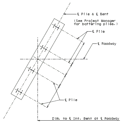
| Note: | The following are details and dimensions for the Plan View on the Front Sheets. |
| Details for unsymmetrical roadways will require dimensions tying Centerline Lane to Centerline Structure. |
751.32.4 Reinforcement
751.32.4.1 General
|
|
| Part Elevation | Section Thru Beam |
|---|---|

|
|
| Part Plan | |
|
|
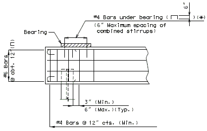
| * #4 Bars ( | |
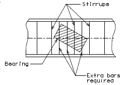
| Reinforcement Under Bearings | |
|---|---|

| |
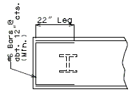
| Transverse Beam Steps - Over 3" or Steps Accumulating Over 3" | |
| |
| Part Plan | |
|---|---|

| |
| Over 3" thru 12" | Over 12" |
| Longitudinal Beam Steps | |