751.17 Concrete Slab Bridges: Difference between revisions
m Per BR, numerous minor clarifications related to barrier pay items |
|||
| Line 156: | Line 156: | ||
:A 3” thick future wearing surface (35psf) shall be considered on the roadway. | :A 3” thick future wearing surface (35psf) shall be considered on the roadway. | ||
:''' | :'''Barrier/Railing ''' | ||
:For slab overhang design, assume the weight of the | :For slab overhang design, assume the weight of the barrier or railing acts at the centroid of the barrier or railing. | ||
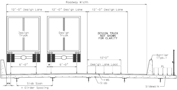
[[Image:751.20.2.2.jpg|center|750px]] | [[Image:751.20.2.2 2020.jpg|center|750px]] | ||
<center>(*) 12" For slab overhang design (LRFD (3.6.1.3.1), 2'-0" for other design</center> | <center>(*) 12" For slab overhang design (LRFD (3.6.1.3.1), 2'-0" for other design</center> | ||
| Line 303: | Line 303: | ||
:("T" and "D" are based on 3" clearance which includes the integral wearing surface to the top of the longitudinal bar.) | :("T" and "D" are based on 3" clearance which includes the integral wearing surface to the top of the longitudinal bar.) | ||
(**) For Roadway with slab drains, use 10" minimum. | (**) For Roadway with slab drains, use 10" minimum. For Roadways that require additional reinforcement for resisting moment of the edge beam 20" minimum. Check for adequate space for development of barrier or railing reinforcement. | ||
[[Category:751 LRFD Bridge Design Guidelines]] | [[Category:751 LRFD Bridge Design Guidelines]] | ||
Revision as of 11:59, 5 August 2020
751.20.1 General
This article illustrates the general design procedure for Continuous Concrete Slab Bridge using AASHTO LRFD Bridge Design Specifications.
751.20.1.1 Material Properties
| Concrete: | ||
|---|---|---|
| Unit weight of reinforced concrete, | ||
| Continuous Cast-In-Place Solid/Voided Concrete Slab | ||
| Class B-2 | ||
| Precast Prestressed Multicell Voided Concrete Girders | ||
| Class A-1 | ||
| <math\, >n=8</math> | ||
| Intermediate bent columns, end bents (below construction joint at bottom of slab) in continuous concrete slab bridges | ||
| Class B-1 | ||
| Class B, Open bent, footing | ||
| Modulus of elasticity,
| ||
| Where: | ||
| f'c in ksi | ||
| wc = unit weight of nonreinforced concrete = 0.145 kcf | ||
| K1 = correction factor for source of aggregate | ||
| ---- = 1.0 unless determined by physical testing | ||
| Modulus of rupture,
= 0.24 LRFD 5.4.2.6 | ||
| Where: | ||
| f'c in ksi | ||
| Reinforcing steel: | ||
| Minimum yield strength, | ||
| Steel modulus of elasticity | ||
| Unit weight of future wearing surface, | ||
751.20.2 Design
751.20.2.1 Limit States and Load Factors
In general, each component shall satisfy the following equation:
Where:
| = Total factored force effect | |
| = Force effect | |
| = Load modifier | |
| = Load factor | |
| = Resistance factor | |
| = Nominal resistance | |
| = Factored resistance |
Limit States
The following limit states shall be considered for slab and edge beam design:
- STRENGTH - I
- SERVICE - I
- FATIGUE
- EXTREME EVENT - II
Resistance factors
For STRENGTH limit state,
- Flexure and tension of reinforced concrete, = 0.90
- Shear and torsion, = 0.90
For all other limit states, = 1.00
751.20.2.2 Loads
Permanent (Dead) Loads
Permanent loads include the following:
- Slab weight
- Future Wearing Surface
- A 3” thick future wearing surface (35psf) shall be considered on the roadway.
- Barrier/Railing
- For slab overhang design, assume the weight of the barrier or railing acts at the centroid of the barrier or railing.
Gravity Live Loads
Gravity live loads include vehicular, dynamic load allowance, and pedestrian loads.
- Vehicular
- The design vehicular live load HL-93 shall be used. It consists of either the design truck or a combination of design truck and design lane load.
- For slab design, where the primary strips are longitudinal, the force effects shall be determined on the following basis:
- The longitudinal strips shall be designed for all loads specified in AASHTO Article 3.6.1.3.3 includuing lane load.
- For the purpose of slab design, the lane load consists of a load equal to 0.640 klf uniformly distributed over 10 feet in the transverse direction.
For precast prestressed multicell girders, live load shall be distributed according to AASHTO LRFD Tables 4.6.2.2.2b-1, 4.6.2.2.2d-1, 4.6.2.2.3a-1 and 4.6.2.2.3b-1 for both moment and shear.
Dynamic Load Allowance
The dynamic load allowance replaces the effect of impact used in AASHTO Standard Specifications. It accounts for wheel load impact from moving vehicles. For slabs, the static effect of the vehicle live load shall be increased by the percentage specified in Table below.
| Slab Component | |
|---|---|
| Deck Joints – All Limit States | 75% |
| All Other Limit States | 33% |
The factor to be applied to the static load shall be taken as:
The dynamic load allowance is not to be applied to pedestrian or design lane loads.
Multiple Presence Factor, :
The multiple presence factor accounts for the probability for multiple trucks passing over a multilane bridge simultaneously.
| = | 1.20 for 1 Loaded Lane |
| 1.00 for 2 Loaded Lanes | |
| 0.85 for 3 Loaded Lanes | |
| 0.65 for more than 3 Loaded Lanes |
Pedestrian
Pedestrian live load on sidewalks greater than 2 ft wide shall be:
| = | 0.075 ksf |
This does not include bridges designed exclusively for pedestrians or bicycles.
For Additional Design Information, see LRFD 5.14.4.2
751.20.3 Details
751.20.3.1 Solid Slabs
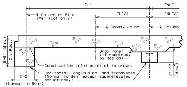
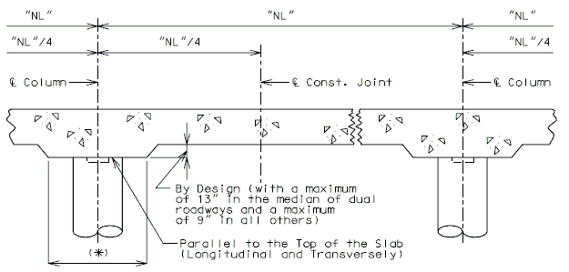
SLAB LONGITUDINAL SECTIONS - SOLID SLABS
- Note:
- All longitudinal dimensions shown are horizontal.
- Note:
751.20.3.2 C.I.P. Voided Slabs
SLAB LONGITUDINAL SECTIONS - CAST-IN-PLACE VOIDED SLAB
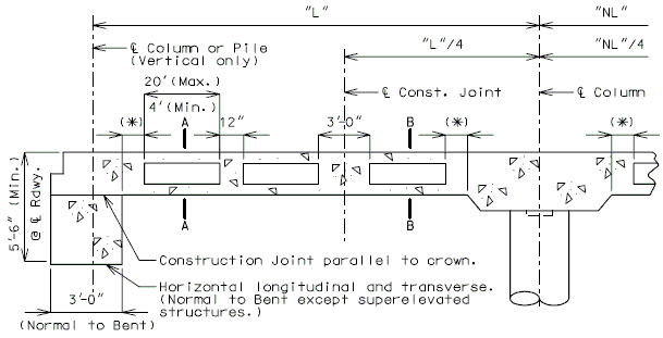
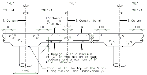
- (*) 3'-0" or greater than or equal to 5% of span length.
- (**) By Design (6" increments measured normal to the centerline of bent) (The minimum is
- equal to the column diameter + 2'6")
- (*) 3'-0" or greater than or equal to 5% of span length.
- Note:
- All longitudinal dimensions shown are horizontal (Bridges on grades and vertical curves, included).
- For sections A-A and B-B, see below.
SLAB CROSS SECTION

| HALF SECTION A-A CENTER OF SPAN |
HALF SECTION B-B NEAR INTERMEDIATE BENT |
| Sonovoids are produced in half sizes 2" to 18". D = 4" to 36" T=19" (Min. preferred. Consult Structural Project Manager prior to the use of a thinner slab.) |
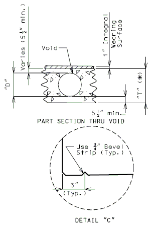 |
Notes:
(*) Increase the Dimension "T" by 1/2" for #14 bars placed in the top or bottom of the slab.
- Increase the Dimension "T" by 1" for #14 bars placed in the top and bottom of the slab.
- ("T" and "D" are based on 3" clearance which includes the integral wearing surface to the top of the longitudinal bar.)
(**) For Roadway with slab drains, use 10" minimum. For Roadways that require additional reinforcement for resisting moment of the edge beam 20" minimum. Check for adequate space for development of barrier or railing reinforcement.