751.13 Expansion Joint Systems: Difference between revisions
| Line 150: | Line 150: | ||
|colspan="7" align="left"|'''2''' Typical providers are Watson Bowman Acme, RJ Watson and D.S. Brown. Variable steel extrusion (rail) profiles are available from these manufacturers that can provide greater flexibility to accommodate new construction or special repair construction situations. Details of these variable steel profiles are available on their websites for design and detailing. Commonly used profiles are shown in the EPG and are generically shown on bridge plans. | |colspan="7" align="left"|'''2''' Typical providers are Watson Bowman Acme, RJ Watson and D.S. Brown. Variable steel extrusion (rail) profiles are available from these manufacturers that can provide greater flexibility to accommodate new construction or special repair construction situations. Details of these variable steel profiles are available on their websites for design and detailing. Commonly used profiles are shown in the EPG and are generically shown on bridge plans. | ||
|- | |- | ||
|colspan="7" align="left"|'''3''' For non-skewed bridge, 5” strip seal gland can be used for movement perpendicular to joint greater than 3 1/2” but less than or equal to 4 1/2” if approved by SPM or SLE and meets other design requirements. Movement capacity may need to be reduced as skew increase to meet Wmax limit and racking limit. On use of 5” Strip Seal: A 5” seal may work where the max opening is less than 4” but skew effect may require a 5” seal. Structural Project Manager or Structural Liaison Engineer (SPM or SLE) approval required in this instance or just when max opening exceeds 4”. | |colspan="7" align="left"|'''3''' For non-skewed bridge, 5” strip seal gland can be used for movement perpendicular to joint greater than 3 1/2” but less than or equal to 4 1/2” if approved by SPM or SLE and meets other design requirements. Movement capacity may need to be reduced as skew increase to meet Wmax limit and racking limit. On use of 5” Strip Seal: A 5” seal may work where the max opening normal to joint is less than 4” but skew effect may require a 5” seal. Structural Project Manager or Structural Liaison Engineer (SPM or SLE) approval required in this instance or just when max opening parallel to roadway exceeds 4”. | ||
|- | |- | ||
|colspan="7" align="left"|'''4''' If minimum gap requirements cannot be achieved at suggested maximum installation temperature then with SPM approval reduce temperature in 10°F increment to achieve minimum gap requirements for installation. Report minimum and maximum installation temperature on the plan. | |colspan="7" align="left"|'''4''' If minimum gap requirements cannot be achieved at suggested maximum installation temperature then with SPM approval reduce temperature in 10°F increment to achieve minimum gap requirements for installation. Report minimum and maximum installation temperature on the plan. | ||
| Line 158: | Line 158: | ||
For rehab structure without resetting armors, use gap at 60°F from existing plan then verify other require values from that point. If any of requirements does not meet then discuss with SPM for other alternate or guidance. | For rehab structure without resetting armors, use gap at 60°F from existing plan then verify other require values from that point. If any of requirements does not meet then discuss with SPM for other alternate or guidance. | ||
Adjust all values as needed for additional movement due to end rotation of the beam. | Adjust all values as needed for additional movement due to end rotation of the beam. | ||
Revision as of 12:34, 1 November 2017
 |
 |
 |
 |
751.13.1 Expansion Joint Systems
751.13.1.1 General
The number of movable deck joints in a structure should be minimized or eliminated in favor of the preferred and more commonplace integral bridge construction following the integral bridge maximum construction length limits given in EPG 751.14.1.2 Girder Limits and Preferences and EPG 751.22.1.4 Span and Structure Lengths. When deck joints are required, they should be avoided over roadways, railroads, sidewalks, other public areas, and at the low point of sag vertical curves.
New and replacement bridges should be joint-free when possible. Redeckings should be made joint-free when possible; expansion joints should only be considered if it is structurally practical. Rehabilitation strategy should be the elimination of existing joints wherever practical.
A closed sealed joint should be used wherever practical. Special challenges in utilizing these types of joint systems include addressing noncompressible debris that can be lodged in openings and snowplowing impacts.
Interchangeability-used terms are “opening”, “gap” and “width; and “installation” and “setting”.
Guidelines herein may be supplementary to AASHTO LRFD unless otherwise instructed.
Types of Jointed Deck Systems (listed in order of increasing ability to not pass debris and then water):
- Deck Joints
- Open Joints
- Closed Joints
- Waterproofed Joints (open or closed joints with troughs)
- Sealed Joints
- Joint Seals
- Compression Seals
- Poured Seals
- No Deck Joints
- Integral Bridge End Bents (new bridges, preferred, limited lengths)
- Semi-Integral End Bents (rehabilitation bridges)
- Sliding Slab over Backwall (can pass water if not sealed properly)
751.13.1.1.1 Design Purpose
Expansion joint Systems should:
- be quiet
- be safe, unobtrusive and provide a smooth ride
- be tolerant of snow plows and robust
- be watertight (sealed joints)
- be capable of self-cleaning or debris tolerant
- be capable of accommodating design movements
- be durable as adjacent deck
- be maintenance-free on performance as made possible by good design over scheduled maintenance checks in short term, and a commonly recognized expected length of usable service life in long term
751.13.1.1.2 Design Movements and Loads at the Strength and Service Limit States can Include
- deformations
- displacements
- thermal expansion and contraction movements
- creep and shrinkage* for concrete
- girder end rotation for steel
- traffic loading
- construction loading and tolerances
- inaccuracies in installation
* For concrete superstructures, initial opening may be less due to creep and shrinkage LRFD 14.5.3.2
751.13.1.1.3 Open and Closed Joints
Finger plates are referred to as “open” joints. MoDOT bridge inspection reports refer to all sealed joints and flat plates as “closed” joints recognizing that all or some roadway contaminants are not passable through these types of joints. In this article, joints that are sealed will be referred to as “sealed” and additionally as “closed” in recognition of bridge inspection reporting practices. A “sealed” joint means that no contaminants are passable, i.e. the joint is watertight.
751.13.1.1.4 Self-Cleaning Sealed Systems
All sealed joint systems are designed for placement in the deck with protruding seals (seals that extend beyond the armor at the outside edge of deck). This type of placement of seals are deigned to drain water and debris from the seal cavities to keep them as clean as possible, i.e. “self-cleaning”, instead of running the armor and seals up into and along the barrier face trapping debris and water.
751.13.1.1.5 Skewed Effects and Continuous Expansion Joints (Sealed Joints)
The thermal movements of skewed bridges with skewed expansion joints can cause relative movement between the armor in the two orthogonal directions associated with the longitudinal orientation of an expansion joint system. Both normal and transverse movements relative to the expansion joint system will add stress to joint seals placed between the armor since the joint is a continuous expansion joint. An expansion is made continuous by connection of the seal to the armor. The transverse movement is referred to as racking. Asymmetrical movement can also occur along the length of skewed expansion joints where the acute corners of a skewed bridge can stretch and grow along the diagonal. This type of racking movement is not considered. For squared expansion joints on skewed structures, transverse movement of the joint is unlikely.
Thermal movements of curved structures can either move along the line of curvature or tangentially between fixed points. Both squared and skewed joint orientations are possible based on radial or parallel bent placement respectively which will affect expansion joint movement considerations.
751.13.1.1.6 Curvature Effects
Horizontally curved bridges and bridges with other special geometric elements, such as splayed or bent girders, do not necessarily expand and contract in the longitudinal direction of the girders. Refined analysis of the entire bridge including superstructure and substructure elements may be necessary to characterize the thermal movement of complex bridges. Refined analysis of horizontally curved, steel-girder bridges is recommended to estimate thermal effects because even a slight curvature may develop large radial forces at bearings. Refer to LRFD 14.5.1.2 for laterally unrestrained curved superstructures.
The following four figures are copied from FDOT for guidance.
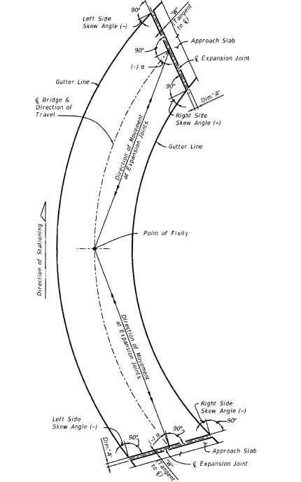
Fig. 751.13.1.1.6.1: Curved Bridge (Single Continuous Unit) with Skewed Joints
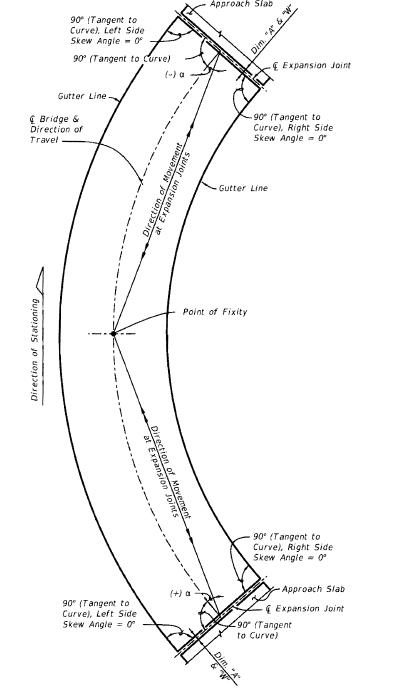
Fig. 751.13.1.1.6.2: Curved Bridges (Single Continuous Unit) with Radial Joints
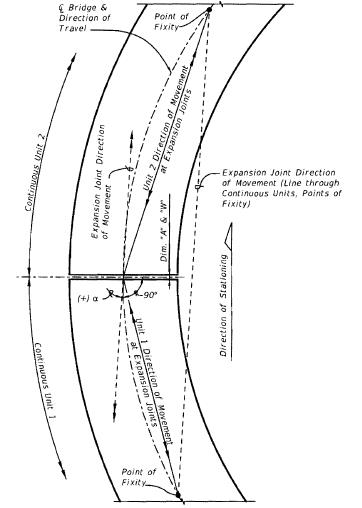
Fig. 751.13.1.1.6.3: Curved Bridges (Multiple Continuous Units) with Radial Joints
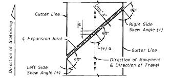
Fig. 751.13.1.1.6.4: Straight Bridge with Skewed Joints
751.13.1.1.7 Movement Range
The required movement range is equal to the total anticipated movement; that is, the difference between the widest and the narrowest opening of a joint (including thermal movement, shrinkage, and creep). However, MoDOT does not consider shrinkage and creep for conventional bridge design (bridges of usual lengths and expansion movements) because minimum opening (gap), Wmin parallel to RDWY will conservatively account for some shrinkage and creep effect.
751.13.1.1.8 Joint (Steel) Armor Requirements
For new and replacement bridge and redecking jobs, all expansion and contraction joints should be armored.
For rehabilitation bridge jobs, steel armor is recommended when deck conditions adjacent to expansion area are not sound or a long service life is expected as in the case of a concrete overlay. Using steel armor should be based on actual field conditions and future expectations of bridge with consideration of cost also important.
| LRFD 14.5.3.2 |
751.13.1.1.9 Pedestrian and Bicycle Effects
Cover plates should be used over expansion openings at sidewalks. Where bicycles are anticipated in the roadway, the use of special cover plates in shoulder area should be considered. Consult the Structural Project Manager or Structural Liaison Engineer if special cover plates should be used. LRFD 14.5.3.2
751.13.1.1.10 Rehabilitation Bridge Movement
Expansion for rehabilitation joint replacement or repair work should be investigated from inspection reports. History of movement and effects of bridge movement may be important in considering replacement or repair or elimination of existing deck joints. Movement may be more accurately predicted from frequent and/or seasonal inspection data.
751.13.1.1.11 Proprietary and Nonproprietary Expansion Joint Systems
All seal joint systems to be used on MoDOT bridges are proprietary and tested, manufactured and sold under trademarked names and details. MoDOT utilizes these systems but because design information is provided by the manufacturers for their design, each system must be checked using relative design conditions (bridge width, length and skew related to expansion movements, temperature range, serviceability, installation) expected over the life of the joint system. MoDOT combines the specificity necessary for the required armor anchoring (studs and spacing, details of connections to girders including plates and bolts details) with generic details of the seal and armor required and the allowed proprietary names of the seal joint system prequalified by design validating its use for a specific bridge expansion opening location. Tables of design information are included and some are copied referring to these systems.
Finger plate and flat plate expansion joint systems are nonproprietary.
751.13.1.1.12 Expansion Type Selection Table
If an expansion joint system is not specified on the Design Layout, but due to the length of the structure, an expansion joint system is required, consult the Structural Project Manager or the Structural Liaison Engineer for the type to be used. The roadway surface gap, W, (except flat and finger plates) for a transverse deck joint, measured in the direction of travel shall satisfy:
For single gaps (opening or width):
- Maximum W ≤ 4" (Preferred) LRFD 14.5.3.2
- Minimum W ≥ 1” * (All joint types but W ≥ ½” preferred for strip seal)
- * For concrete superstructures, initial opening may be less due to creep and shrinkage.
- For special cases a W = 5" maximum opening may be permitted to allow larger movement and to meet other requirements if approved by Structural Project Manager or Structural Liaison Engineer.
- Absolute clear gap normal to joint shall be ≥ ½” for all expansion joint types.
- Shrinkage and creep effect is not considered in the movement computation but minimum W will buffer for some shrinkage and creep effect.
- Maximum movement, Mmax will depend on actual Gmax, Gmin, manufacturer-recommended racking limits (skew effect), Wmax, Wmin, and manufacturer installation requirements. G = Gap normal to joint. Movement parallel to RDWY, M = Wmax – Wmin.
| Expansion Joint System |
Allowable Movement (⊥ to Joint) |
Allowable Skew for Specific Expansion Joint System |
For New Structure |
For Rehab | Field Installation Temperature | |
|---|---|---|---|---|---|---|
| Max., °F | Min., °F | |||||
| Preformed Silicone or EPDM Seal1,2 | ≤ 4” | ≤ 30˚ | X | 70 | 40 | |
| Reduce movement capacity for greater skews | 30˚ < 45˚ | X | ||||
| Preformed Compression Seal2 | ≤1.8” | ≤ 20˚ | X | X | 70 | 40 |
| Strip Seal2 | ≤ 4 1/2” 3 | ≤ 55˚ 3 | X | X | 904 | 40 |
| Flat Plate | > 45˚ | X | X | 904 | 40 | |
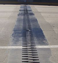
| Finger Plate | X | X | 904 | 40 | ||
| Use flat plate expansion joint system on curved structures or/and skews over 45°. | ||||||
| 1 This system can be considered for a short term solution or in ideal circumstances for a 5 to 7 years solution (Rehabilitation job). Adhesion seal are not anticipated to last long and this type of seal joint is especially not anticipated to perform long on highly skewed structures. | ||||||
| 2 Typical providers are Watson Bowman Acme, RJ Watson and D.S. Brown. Variable steel extrusion (rail) profiles are available from these manufacturers that can provide greater flexibility to accommodate new construction or special repair construction situations. Details of these variable steel profiles are available on their websites for design and detailing. Commonly used profiles are shown in the EPG and are generically shown on bridge plans. | ||||||
| 3 For non-skewed bridge, 5” strip seal gland can be used for movement perpendicular to joint greater than 3 1/2” but less than or equal to 4 1/2” if approved by SPM or SLE and meets other design requirements. Movement capacity may need to be reduced as skew increase to meet Wmax limit and racking limit. On use of 5” Strip Seal: A 5” seal may work where the max opening normal to joint is less than 4” but skew effect may require a 5” seal. Structural Project Manager or Structural Liaison Engineer (SPM or SLE) approval required in this instance or just when max opening parallel to roadway exceeds 4”. | ||||||
| 4 If minimum gap requirements cannot be achieved at suggested maximum installation temperature then with SPM approval reduce temperature in 10°F increment to achieve minimum gap requirements for installation. Report minimum and maximum installation temperature on the plan. | ||||||
For new structure and resetting armor, assume 2” gap normal to joint at RDWY surface at 60°F and compute require other values from that point for strip seal and preformed silicone or EPDM seal expansion joint. If any of required value does not meet the requirements then adjust the gap at 60°F and recompute the required values. Report allowed installation gap normal to joint at RDWY surface at air/surface temperature on the plans.
For rehab structure without resetting armors, use gap at 60°F from existing plan then verify other require values from that point. If any of requirements does not meet then discuss with SPM for other alternate or guidance.
Adjust all values as needed for additional movement due to end rotation of the beam.
- Service Life Expectancy
- See the following figures for Silicon seal expansion joint system, Preformed silicone or EPDM seal expansion joint system and Preformed compression seal expansion joint system (for Strip seal expansion joint system, see 751.13.4.1 General).
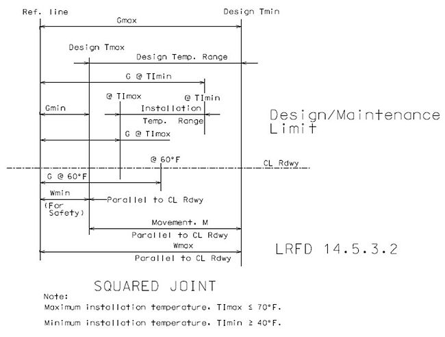
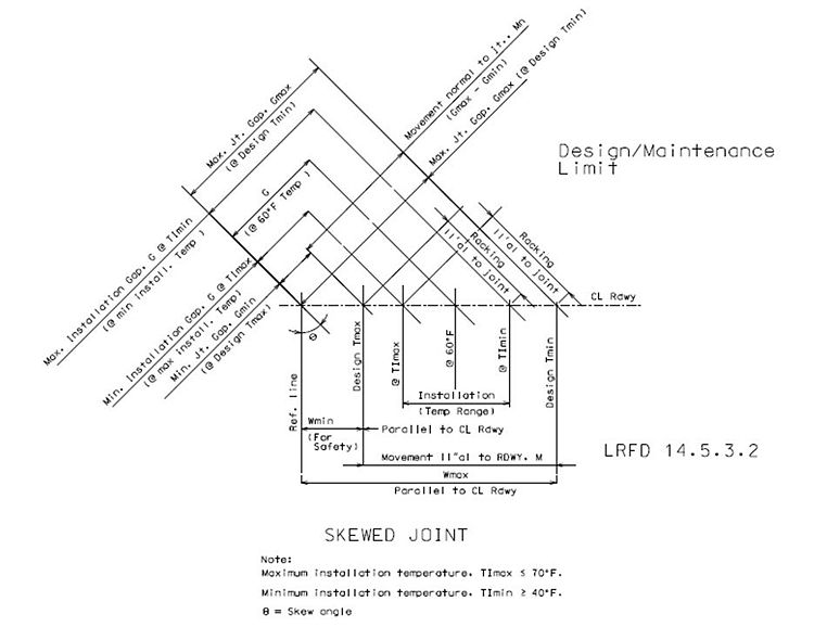
- Notations:
- Wmin = Minimum gap parallel to center line of RDWY at roadway surface
- Wmax = Maximum gap parallel to center line of RDWY at roadway surface
- Gmin = Minimum gap perpendicular to joint at maximum design temperature
- Gmax = Maximum gap perpendicular to joint at minimum design temperature
- Movement Calculation (in the direction of travel), M:
- M = ∆=γ(∝)(design temperature range)(L x 12) or M = Wmax – Wmin
- Load factor, γ =1.2 for New bridges and superstructure replacements
- 1.0 for Rehabilitation job with replacing armor “If inspection data verifies bridge movement” other wise use 1.2. (See SPM or SLE).
- Design Temp. Range = Design Tmax – Design Tmin
- Coefficients of Thermal Expansion, (∝):
- Steel: Thermal - 0.0000065 ft/ft/F°
- Concrete: Thermal - 0.0000060 ft/ft/F°
- L = expansion length, Ft
- θ = Skew angle
- Temperature Range From 60°F:
- Temperature Range is based on a design installation temperature at 60°F.
| Rise | Fall | Design Temperature Range | |
|---|---|---|---|
| Steel Structures | 60°F | 90°F | (From -30° to 120°) 150°F |
| Concrete Structures | 50°F | 70°F | (From -10° to 110°) 120°F |
- Actual Expansion Length, (L):
- When expansion joints are used for long span structures with deep girders, movement calculations should also consider the bearings and possible resulting girder rotation.
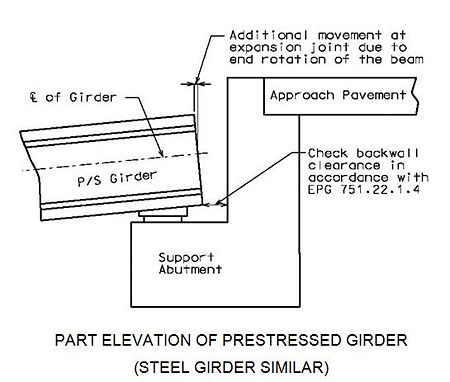
PART ELEVATION OF PRESTRESSED GIRDER (STEEL GIRDER SIMILAR)
- Note: For steel girder check backwall clearance in accordance with EPG 751.11.3.2 Elastomeric Bearings for Steel Girders.
- Installation Gap Normal To The Joint:
- The installation gap should be adjusted for temperatures above or below the design installation temperature. Movement normal to joint for a 10°F change in temperature should be indicated on the plans to the nearest 1/16” by using the appropriate note.
- Movement normal to the joint for 10°F change in temperature =
- (γ)(α)(10°F)(Lx12)(cos θ)
- Movement normal to the joint for 10°F change in temperature =
751.13.1.2 Expansion and Contraction Length
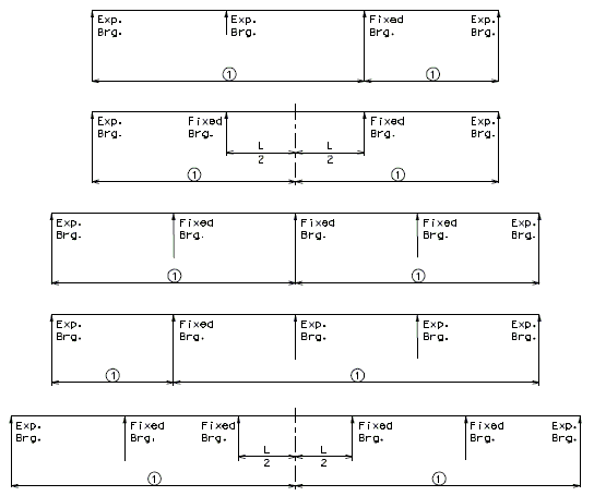
Note:
![]() = Expansion and contraction length.
= Expansion and contraction length.
For configurations not shown, a temperature force distribution analysis may be necessary to estimate the point of thermal origin.
751.13.1.3 Expansion Joint System on Skewed Curved Structures
Expansion Joint System on Skewed Curved Structures
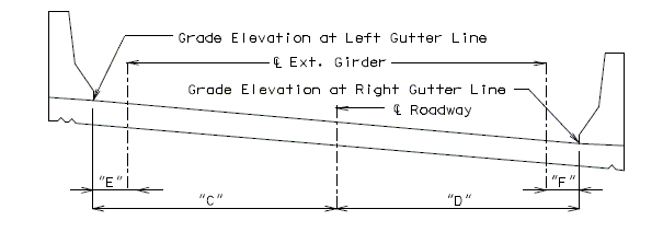
Add the “Section Thru Centerline Expansion Gap” and the Table shown below to the Expansion Joint System sheet for skewed curved structures.
PART PLAN
SECTION THRU EXPANSION GAP
| BENT NO. | GRADE ELEVATION | ANGLE | HORIZONTAL DIMENSIONS | ||||||
| LEFT GUTTER LINE | RDWY. | RIGHT GUTTER LINE | |||||||
| "A" | "B" | "C" | "D" | "E" | "F" | ||||
751.13.1.4 Details of Substructure Protection
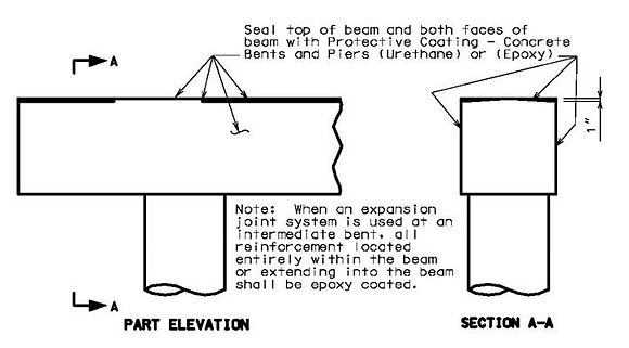
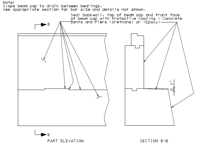
A protective coating shall be applied to concrete surfaces exposed to drainage from the roadway. Indicate surface to be coated on plans. Urethane resembles black tar which is used where aesthetics is not a concern, otherwise use epoxy.
751.13.1.5 Silicone Seal Expansion Joint System
Silicone seal expansion joint systems (SISEJS) shall not be used for normal contract new or rehabilitation jobs effective November 2011. This system is considered a short term sealing solution primarily good for maintenance operations. This system should be considered only for small movements and when watertightness is of secondary importance LRFD C14.5.6.5.
SISEJS may be considered for special situations when agreed upon by both the district bridge engineer and Bridge Division. Examples include short deck spans, sawed joints or situations where contracted joint work is intended to supplement MoDOT’s bridge maintenance work scheduling (maintenance type applications).
Archived SISEJS details including armor and reinforcing steel details are available upon request from the Bridge Division.
751.13.2 Preformed Silicone or EPDM Seal Expansion Joint System
751.13.2.1 General
This system can be used for movement up to 4” perpendicular to joint if meets all required requirements.
For rehab job without resetting armor use gap @ 60°F (normal to the joint) from the existing plan and compute other required values. For new job or when resetting armor, assume 2” gap @ 60°F (normal to the joint) and compute other required values and adjust gap at 60°F as necessary until all requirements are met. Check minimum and maximum opening along centerline for RDWY.
Preformed Silicone or EPDM Seal Expansion Joint System Features and Permissibility
1. For rehabilitation jobs only.
2. Designed to carry low stress at the bonded joints.
3. Directs debris to the edges where the seal is bonded and stronger and not to the center where typically seals are weaker and prone to puncture.
4. Seals will bond equally well to steel, concrete and elastomeric or polymer concrete surfaces. These systems can also be used to reseal failed strip seal joints.
5. Not preferable, but in special situations approved by SPM or SLE, can work well with irregular, tapered and spalled joint openings. It is easily repaired and field spliceable for quick installations and maintenance repair. Bond can be used to fix punctures or replace whole sections and splice sections; install times and open times are quick.
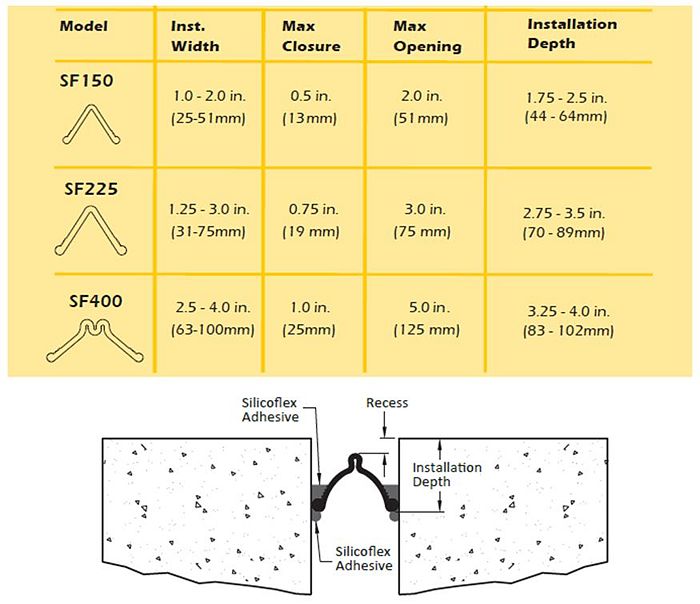
751.13.2.1.1 RJ Watson (Silicoflex Joint Sealing System)
Acceptable variations on installation platforms (Copied from R J Watson, Inc. Brochure):
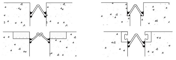
Note: It may be more practical to re-insert a strip seal in an existing (in-place) strip seal armor rail.
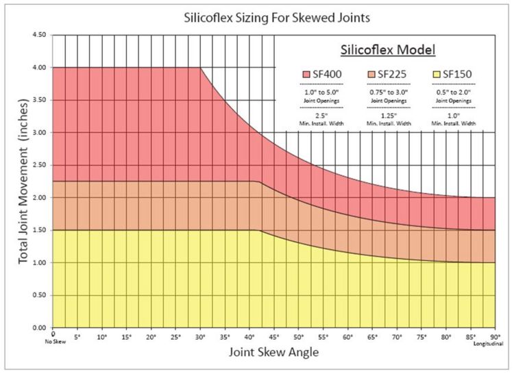
Skewed Effects: Skewed Silicoflex expansion seals can experience rapid decreased performance for SF400 at skews above 30 degrees and for SF225 and SF150 at skews above 42 degrees as shown in this graph produced by R J Watson Inc. and copied from http://www.rjwatson.com/wp-content/uploads/silicoflex-brochure-may.pdf. Total joint movement shown in following graph is normal to joint.
751.13.2.1.2 Watson Bowman Acme (Wabo SPS Preformed Silicone Joint Sealing System)
Wabo SPS expansion joint system can be used for skewed joints up to 45 degrees. This joint seal allows 15% of allowed movement normal to joint for racking.
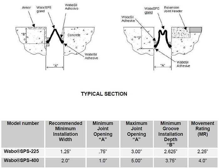
Copied from Watson Bowman Acme web site.
751.13.2.1.3 D.S. Brown Expansion Joint System (V – Seal)

V-Seal is a preformed extruded EPDM seal. This joint seal allows 15% of allowed movement normal to joint for racking.
EPDM is an extremely durable synthetic rubber roofing membrane (ethylene propylene diene terpolymer) widely used in low-slope buildings in the United States and worldwide. Its two primary ingredients, ethylene and propylene, are derived from oil and natural gas.
RJ Watson and Watson Bowman Acme use silicone rubber seals with silicone locking adhesives, D.S. Brown uses a rubber seal (EPDM) and a two–component epoxy adhesive.
Typical application: Existing expansion joint armor (steel angles or strip seal extrusions)
751.13.2.2 Preformed Silicone or EPDM Seal Expansion Joint System Summary
Maximum opening parallel to RDWY is = value from above summary/ cos(skew) but not more than allowed “W”.
- Check 1" ≤ W ≤ 4" (preferred). W up to 5” can be considered with SPM or SLE approval. W = gap at top slab in the direction of travel, in inch for new structure and resetting rehab jobs.
Expansion joint design shall meet minimum and maximum installation width (opening) normal to joint, minimum opening (maximum closure) normal to joint, maximum opening normal to joint and maximum opening parallel to RDWY requirements and racking (skew) limit.
For example, skew = 30° and for “SF400” seal from above summary maximum movement normal joint = 4” and maximum opening normal joint = 5” and assumed design minimum opening normal to joint =1”. Maximum opening parallel to RDWY = 5/cos(30) = 5.77” > W = 4”. Movement normal to joint shall be reduced. Maximum opening normal to joint = 4 cos(30) = 3.46”. Maximum movement normal to joint allowed = maximum opening normal to joint – minimum opening normal to joint = 3.46” – 1” = 2.46” instead of 4”.
If skew = 45°, “SF400” seal from R J Watson graph maximum movement normal joint = 2.8” and assumed design minimum opening normal to joint =1”. Maximum opening normal joint = maximum movement normal joint + minimum opening normal to joint = 3.8”. Maximum opening parallel to RDWY = 3.8/cos(45) = 5.37” > W = 4”. Movement normal to joint shall be reduced. Maximum opening normal to joint = 4 cos(45) = 2.83”. Maximum movement normal to joint allowed = maximum opening normal to joint – minimum opening normal to joint = 2.83” – 1” = 1.83” instead of 4” if other design requirements meet.
751.13.2.3 Preformed Silicone or EPDM Seal Expansion Joint System - Details
| Bridge Standard Drawings |
| Preformed Silicone or EPDM Seal Expansion Joint System |
751.13.2.4 Design Examples
751.13.2.4.1 Design Example 1
New or existing steel structure with setting or resetting gap respectively, Expansion Length, L = 130 FT, skew θ = 45°
- Design temperature range -30° to 120° => Design Tmax = 120°F
- Design Tmin = -30°F
- Load factor, = 1.2 (Use 1.2 for new structure; Use 1.2 for existing structure when bridge inspection data does not verify bridge movement.)
- ∝ = 0.0000065 ft/ft/F°
Step 1: Set installation gap
Assume installation gap value at 60°F for resetting armors structure and modify value as needed to meet other requirements. Gap normal to joint at RDWY surface between armors for 60°F, G = 1 ¾” assumed
Step2: Determine gaps for range of installation temperatures
Find installation gap normal to joint at maximum installation temperature = 70°F and minimum installation temperature = 40°F.
Compute gap normal to joint @ 10 degree increments between min. and max. installation temp. and report on the plans.
Gap normal to joint at max. installation temp. (70°F) at RDWY surface, G at Timax
- = G - (γ)(α)(70°F - 60°F)(L*12)(cos θ) = 1 11/16”
Gap normal to joint at 50°F installation temp. at RDWY surface, G at 50°F
- = G + (γ)(α)(60°F – 50°F)(L*12)(cos θ) = 1 13/16”
Gap normal to joint at min. installation temp. (40°F) at RDWY surface, G at Timin
- = G + (γ)(α)(60°F – 40°F)(L*12)(cos θ) = 1 15/16”
Min. installation gap normal to joint = 1 11/16” ≥ Seal “150”, “225” and “300” from seal summary table ∴ O.K.
Max. installation gap normal to joint = 1 15/16” ≤ Seal “225”, “300” and “400” from seal summary table ∴ O.K.
∴ SF 225, SPS-225 or V-300 may work. (note: Min. installation gap < Required min. installation gap for Seal “400”
- so Seal “400” should not be used.
Step 3: Compute minimum and maximum gap normal to joint and movement
Find minimum and maximum gap normal to joint and parallel to RDWY at maximum design temperature, design Tmax and minimum design temperature, design Tmin. Find movement normal to joint and parallel to RDWY.
- Information at RDWY surface
- M ‖’al to RDWY, M = γ(∝)(design temperature range)(L x 12) = 1.83“
- M ⊥ to the joint, Mn = M * cos(θ) = 1.29”
- Gap normal to joint at 60°F temp., G = 1.75”, and γ = 1.2
- Minimum joint gap (Maximum closure normal to joint at Design Tmax), Gmin
- = G - (γ)(α)(Design Tmax - 60°F)(L*12)(cos θ)
- =1.23” ≥ Required for SF 225, SPS-225 or V-300 seal size ∴ O.K.
- Minimum opening ‖’al to RDWY, Wmin = 1.23/( cos θ) = 1.74” ≥ 1” ∴ O.K.
- Maximum joint gap (Maximum opening normal to joint at Design Tmin), Gmax
- = G + (γ)(α)( 60°F - Design Tmin)(L*12)(cos θ)
- = 2.52”
- Maximum opening ll’al to RDWY, Wmax = 2.524/( cos θ) = 3.57” ≤ 4” ∴ O.K.
- Note: As per LRFD 14.5.3.2, Wmax ≤ 4”
M ⊥ to the joint, Mn = Gmax – Gmin = 2.52” – 1.23” = 1.29” (Matches previously computed value) ∴ O.K.
Movement ‖’al to RDWY, M = Wmax – Wmin = 3.57” – 1.74” = 1.83” (Matches previously computed value) ∴ O.K.
Step 4: Compare design requirements to manufacturer information (see preformed silicone and EPDM seal summary) and determine all possible seal sizes which will meet the design requirements.
- Note: Max opening parallel to RDWY ≤ 4” preferred or up to 5” max. opening with SPM/SLE approval.
- Gmax = 2.52” ≤ Required for SF 225, SPS-225 or V-300 seal size ∴ O.K
- Gmin = 1.23” ≥ Required for SF 225, SPS-225 or V-300 seal size ∴ O.K.
Step 5: Compare anticipated racking to allowed manufacturer racking limit.
- 1. Check racking (‖’al to joint) for max. design temperature and seal installation temp. range.
- Racking for min. installation temp. case = (130 x 12)(γ)(∝)(120-40)*sin(ɵ)
- = 0.69”
- Racking for 60°F installation temp. case = (130 x 12)(γ)(∝)(120-60)*sin(ɵ)
- = 0.52”
- Racking for max. installation temp. case = (130 x 12)(γ)(∝)(120-70)*sin(ɵ)
- = 0.43”
- Maximum racking for max. design temperature case = 0.69”
- 2. Check racking (‖’al to joint) for min. design temperature and seal installation temp. range.
- Racking for min. installation temp. case = (130 x 12)(γ)(∝)(40-(-30))*sin(ɵ)
- = 0.60”
- Racking for 60°F installation temp. case = (130 x 12)(γ)(∝)(60-(-30))*sin(ɵ)
- = 0.77”
- Racking for max. installation temp. case = (130 x 12)(γ)(∝)(70-(-30))*sin(ɵ)
- = 0.86”
- Maximum racking for min. design temperature case = 0.86”
- Maximum racking for (a) max. design temperature case and (b) min. design temperature case = 0.86”
Step 6: Check skew effect.
- 6.1 RJ Watson: Reduced allowable movement normal to joint as skew increases. No racking check required.
- Read value from manufacture provided graph for skew. For SF225 and skew = 45◦, allowed maximum movement normal to joint from graph = 2.12”.
- Compute max. opening normal to joint allowed
- Maximum movement normal to joint allowed from graph (reduce as skew increase) = 2.12”
- Min. opening required by manufacture or adjusted to meet Wmin requirements = 0.75” (Note: Since Wmin ≥ 1, no adjustment required.)
- A. Max. opening normal to joint allowed by manufacture based on reduced joint movement
- = 2.12” + 0.75” = 2.87”
- A. Max. opening normal to joint allowed by manufacture based on reduced joint movement
- B. Opening normal to joint (value from graph + min. gap by design) = 2.12” + 1.23” = 3.35”
- C. Max. opening normal to joint based on AASHTO limit or SPM approved limit = 4 * cos(skew) = 2.83”
- D. Max. opening normal to joint allowed by manufacture = 3” from seal summary
- E. Allowed max. opening normal to joint = min (A, B, C & D) = 2.83”
- Allowed max movement normal to joint = E – min. opening @ design Tmax
- = 2.83” – 1.23”
- = 1.60” ≥ M to the joint, Mn = 1.29” ∴ O.K.
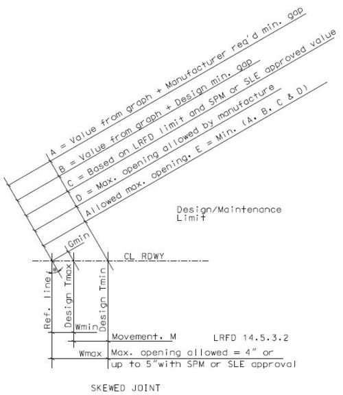
- 1. Max. opening normal to joint @ design Tmax = 2.52” ≤ 2.83” ∴ O.K.
- 2. Max. movement normal to Joint = 1.29” ≤ 1.60” ∴ O.K.
- 3. Max. movement ll'al to RDWY = 1.83” ≤ 1.60/cos(skew) = 2.25” ∴ O.K.
- Skew effect is o.k. since 1, 2 & 3 are o.k.
- Use RJ Watson (Silicoflex Joint seal) SF225
- 6.2 Compare anticipated racking to allowed manufacturer racking limit for Watson Bowman Acme (Wabo) and D.S. Brown
- Wabo allows 15% of allowed movement normal to joint for racking.
- Allowed racking for SPS-225 = 15%*2.25 = 0.34”
- Anticipated max racking = 0.86” > 0.34” racking allowed for Wabo SPS-225 ∴ Wabo SPS-225 N.G.
- D.S. Brown allows 15% of allowed movement normal to joint for racking.
- Allowed racking for V-300 = 15%*3 = 0.45”
- Anticipated max racking = 0.86” > 0.45” racking allowed for V-300 ∴ D S Brown V-300 N.G.
Show on the Plans:
| Manufacturer1 | Preformed Silicone or EPDM Seal System (Designated Name) |
Movement Parallel to RDWY |
① Allowed Installation Gap Normal to Joint @ RDWY Surface @ Air/Surface Temperature 2 |
3 | |||
|---|---|---|---|---|---|---|---|
| @ 40°F | @ 50°F | @ 60°F | @ 70°F | ||||
| RJ Watson (Silicoflex Joint Seal) | SF225 | 1 5/6” | 1 15/16” | 1 13/16” | 1 ¾” | 1 11/16” | ☐ |
| Watson Bowman Acme (Wabo SPS Joint Seal) |
☐ | ||||||
| D.S. Brown (EPDM Joint Seal) | ☐ | ||||||
| ① See Bridge Standard Drawings. | |||||||
| 1 Remove non-applicable manufacturer(s) in table. | |||||||
| 2 The installation temperature shall be taken as the actual air temperature averaged over the 24-hour period immediately preceding installation. | |||||||
| 3 MoDOT Construction personnel will indicate the preformed silicone or EPDM seal expansion joint system installed. | |||||||
751.13.2.4.2 Design Example 2
Existing steel structure without resetting gap, Expansion Length, L = 182 FT, skew θ = 45°, ½” concrete steps at bottom of joint.
- Design temperature range -30° to 120° => Design Tmax = 120°F
- Design Tmin = -30°F
- Bridge inspection data verifies bridge movement. Use load factor, γ = 1.0 for temperature movement computation and installation gap computation
Step 1: Set installation gap.
Assume installation gap value at 60°F for without resetting gap and modify value as needed to meet other requirements. Gap normal to joint at RDWY surface for 60°F installation temp., G = 2 ⅝” assumed
Step2: Determine gaps for range of installation temperatures.
Find installation gap normal to joint at maximum installation temperature = 70°F and minimum installation temperature = 40°F.
Compute gap normal to joint @ 10 degrees increment between min. and max. installation temp. and report on the plans. Gap normal to joint at max installation temp. (70°F) at RDWY surface, G at Timax
- = G - (γ)(α)(70°F - 60°F)(L*12)(Cos θ) = 2 1/2”
Gap normal to joint at 50°F installation temp. at RDWY surface, G at 50°F
- = G + (γ)(α)(60°F – 50°F)(L*12)(Cos θ) = 2 3/4”
Gap normal to joint at min. installation temp. (40°F) at RDWY surface, G at Timin
- = G + (γ)(α)(60°F – 40°F)(L*12)(Cos θ) = 2 13/16”
Min. installation gap normal to joint = 2 1/2” ≥ Seal “400” from seal summary table ∴ O.K.
Max. installation gap normal to joint = 2 13/16” ≤ Seal “225”, “300” and “400” from seal summary table ∴ O.K.
∴ SF 400, SPS- 400 or V- 400 may work.
Step 3: Compute minimum and maximum gap normal to joint and movement.
Find minimum and maximum gap normal to joint and parallel to RDWY at maximum design temperature, design Tmax and minimum design temperature, design Tmin. Find movement normal to joint and parallel to RDWY.
- Information at RDWY surface
- M ‖’al to RDWY, M = γ(∝)(design temperature range)(L x 12) = 2.13“
- M ⊥ to the joint, Mn = M * cos(θ) = 1.51”
- Gap normal to joint at 60°F temp., G = 2.625”, and = 1.0
- Minimum joint gap (Maximum closure normal to joint at Design Tmax), Gmin
- = G - (γ)(α)(Design Tmax - 60°F)(L*12)(cos θ)
- =2.02” ≥ 1 ∴ SF 400, SPS- 400 or V- 400 may work
- Minimum opening ‖’al to RDWY, Wmin = 2.02/(cos θ) = 2.86” ≥ 1” ∴ O.K.
- Maximum joint gap (Maximum opening normal to joint at Design Tmin), Gmax
- = G + (γ)(α)( 60°F - Design Tmin)(L*12)(cos θ)
- = 3.53” ≤ 5” ∴ SF 400, SPS- 400 or V- 400 may work.
- Maximum opening ‖’al to RDWY, Wmax = 3.53/(cos θ) = 4.99” ≤ 5” ∴ O.K.with SPM or SLE approval
- Note: As per LRFD 14.5.3.2, Wmax ≤ 4”
- M ⊥ to the joint, Mn = Gmax – Gmin = 3.53” – 2.02” = 1.51” (Matches previously computed value) ∴ O.K.
Movement ‖’al to RDWY, M = Wmax – Wmin = 4.99” – 2.86” = 2.13” (Matches previously computed value) ∴ O.K.
- Information at bottom of joint
- Gmin at bottom joint = Gmin at top – 2*concrete step overhang = 2.02” – 2*0.5” = 1.02” ≥ ½” ∴ O.K.
- Note: Minimum opening normal to joint = ½” absolute
Step 4: Compare design requirements to manufacture Information (see preformed silicone and EPDM seal summary) and determine all possible seal sizes which will meet the design requirements.
- Note: Max. opening parallel to RDWY ≤ 4” preferred or up to 5” max. opening with SPM/SLE approval.
- Gmax = 3.53” ≤ Required for SF 400, SPS- 400 or V- 400 seal size ∴ O.K
- Gmin = 2.02” ≥ Required for SF 400, SPS- 400 or V- 400 seal size ∴ O.K.
Step 5: Compare anticipated racking to allowed manufacturer racking limit.
- 1. Check racking (‖’al to joint) for max. design temperature and seal installation temp. range.
- Racking for min. installation temp. case = (182 x 12)(γ)(∝)(120-40)*sin(ɵ)
- = 0.80”
- Racking for 60°F installation temp. case
- = (182 x 12)(γ)(∝)(120-60)*sin(ɵ)= 0.60”
- Racking for max. installation temp. case = (182 x 12)(γ)(∝)(120-70)*sin(ɵ)
- = 0.50”
- Maximum racking for max. design temperature case = 0.80”
2. Check racking (‖’al to joint) for min. design temperature and seal installation temp. range
- Racking for min. installation temp. case = (182 x 12)(γ)(∝)(40-(-30)*sin(ɵ)
- = 0.70”
- Racking for 60°F installation temp. case = (182 x 12)(γ)(∝)(60-(-30)*sin(ɵ)
- = 0.90”
Racking for max. installation temp. case = (182 x 12)(γ)(∝)(70-(-30)*sin(ɵ)
- = 1.00”
- Maximum racking for min. design temperature case = 1.00”
- Maximum racking for (a) max. design temperature case and (b) min. design temperature case = 1.00”
Step 6: Check skew effect.
- 6.1 RJ Watson: Reduced allowable movement normal to joint as skew increase. No racking check required.
- Read value from manufacture provided graph for skew. For SF400 and skew = 45◦, allowed maximum movement normal to joint from graph = 2.75”.
- Compute max. opening normal to joint allowed
- Maximum movement normal to joint allowed from graph (reduce as skew increase) = 2.75”
- Min. opening required by manufacture or adjusted to meet Wmin requirements = 1.00” (Note: Since Wmin ≥ 1, no adjustment required.)
- A. Max. opening normal to joint allowed by manufacture based on reduced joint movement
- = 2.75” + 1.00” = 3.75”
- A. Max. opening normal to joint allowed by manufacture based on reduced joint movement
- B. Opening normal to joint (value from graph + min. gap by design) = 2.75” + 2.02” = 4.77”
- C. Max. opening normal to joint based on AASHTO limit or SPM approved limit = 5* cos(skew) = 3.54”
- D. Max. opening normal to joint allowed by manufacture = 5” from seal summary
- E. Allowed max. opening normal to joint = min (A, B, C & D) = 3.54”
- Allowed max movement normal to joint = E – min. opening @ design Tmax = 3.54” – 2.02” = 1.52”
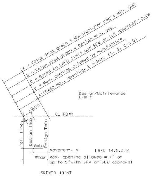
- 1. Max. opening normal to joint @ design Tmax = 3.53” ≤ 3.54” ∴ O.K.
- 2. Max. movement normal to Joint = 1.51” ≤ 1.52” ∴ O.K.
- 3. Max. movement ll'al to RDWY = 2.13” ≤ 1.52/cos(skew) = 2.15” ∴ O.K.
- Skew effect is o.k. since 1, 2 & 3 are o.k.
- Use RJ Watson (Silicoflex Joint seal) SF400
- 6.2 Compare anticipated racking to allowed manufacturer racking limit for Watson Bowman Acme (Wabo) and D.S. Brown
- Wabo allows 15% of allowed movement normal to joint for racking.
- Allowed racking for SPS-400 = 15%*4.00 = 0.60”
- Anticipated max racking = 1.00” > 0.60” racking allowed for Wabo SPS-400 ∴ Wabo SPS-400 N.G.
- D.S. Brown allows 15% of allowed movement normal to joint for racking.
- Allowed racking for V-300 = 15%*4.00 = 0.60”
- Anticipated max racking = 1.00” > 0.60” racking allowed for V-400 '∴ D S Brown V-400 N.G.
Show on the Plans:
| Manufacturer1 | Preformed Silicone or EPDM Seal System (Designated Name) |
Movement Parallel to RDWY |
① Allowed Installation Gap Normal to Joint @ RDWY Surface @ Air/Surface Temperature 2 |
3 | |||
|---|---|---|---|---|---|---|---|
| @ 40°F | @ 50°F | @ 60°F | @ 70°F | ||||
| RJ Watson (Silicoflex Joint Seal) | SF400 | 2 1/8” | 2 13/16” | 2 3/4” | 2 5/8” | 2 1/2” | ☐ |
| Watson Bowman Acme (Wabo SPS Joint Seal) |
☐ | ||||||
| D.S. Brown (EPDM Joint Seal) | ☐ | ||||||
| ① See Bridge Standard Drawings. | |||||||
| 1 Remove non-applicable manufacturer(s) in table. | |||||||
| 2 The installation temperature shall be taken as the actual air temperature averaged over the 24-hour period immediately preceding installation. | |||||||
| 3 MoDOT Construction personnel will indicate the preformed silicone or EPDM seal expansion joint system installed. | |||||||
751.13.3 Preformed Compression Seal Expansion Joint System
751.13.3.1 General
1. Small movement range =>moderate temperature extremes => maintaining resiliency (to permit recovery) => longer life
2. Installation criteria of skew limits and using low temperatures => longer life
- The system can be used for movements normal to joint up to 1.80” with skews ≤ 20°.
- Use where joint movement range can be accurately predicated LRFD C14.5.6.6.
- Use where not in sustained compression for less risk of popping out LRFD 14.5.6.6.
- Installation at lower temperatures is preferred for less risk of installation difficulty and damage (Note on plans).
3. Since installation width requirements not available for this type of joint, compute installation gap normal to the joint at 60°F from manufacture required minimum joint width, Gmin (Assume at highest design temperature) and report on the plans to the nearest 1/16”. Compute installation gap normal to joint @ 40°F, 50°F and 70°F temperature and report on the plans to the nearest 1/16”.
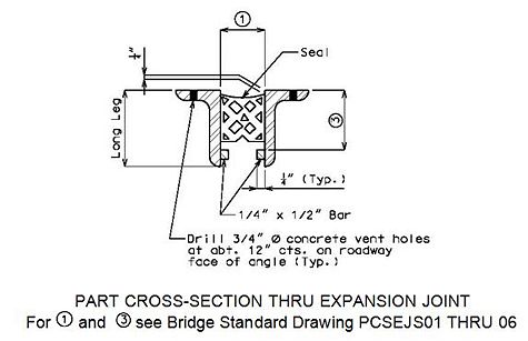
| Seal Width Perpendicular to Joint |
Height ③ | Movement Capacity (M ⊥ to Joint) |
Min. Joint Width, Gmin (⊥ to Joint) |
Max. Joint Width, Gmax (⊥ to Joint) |
① Allowed Installation Gap Normal to Joint @ RDWY Surface @ Air/Surface Temperature1 |
2 | |||
|---|---|---|---|---|---|---|---|---|---|
| @ 40°F | @ 50°F | @ 60°F | @ 70°F | ||||||
| 2.25” | Manufacturer’s Recommended Height | 0.90” | 1.01” | 1.91” | xxx | xxx | xxx | xxx | ☐ |
| 2.5" | Manufacturer’s Recommended Height | 1.00" | 1.13" | 2.13" | xxx | xxx | xxx | xxx | ☐ |
| 3.0" | Manufacturer’s Recommended Height | 1.20" | 1.34" | 2.55" | xxx | xxx | xxx | xxx | ☐ |
| 3.5" | Manufacturer’s Recommended Height | 1.40" | 1.58" | 2.98" | xxx | xxx | xxx | xxx | ☐ |
| 4.0" | Manufacturer’s Recommended Height | 1.65" | 1.75" | 3.40" | xxx | xxx | xxx | xxx | ☐ |
| 4.5" | Manufacturer’s Recommended Height | 1.80" | 2.03" | 3.83" | xxx | xxx | xxx | xxx | ☐ |
| Notes: - Depth of seal shall not be less than width of seal. - Remove non-applicable rows in table. - Size of Armor Angle: Vertical leg of angle shall be a minimum of Manufacturer’s Recommended Height ③ + 3/4". Horizontal leg of angle shall be a minimum of 3". Minimum thickness of angle shall be 1/2". - Check 1" ≤ W ≤ 4" (Preferred) after select seal size, W = gap at top slab in the direction of travel, in inch for new structure and resetting rehab jobs. | |||||||||
| 1 The installation temperature shall be taken as the actual air temperature averaged over the 24-hour period immediately preceding installation. | |||||||||
| 2 MoDOT Construction personnel will indicate the preformed compression seal expansion joint system installed. | |||||||||
751.13.3.2 Preformed Compression Seal Expansion Joint System – Details
Preformed Compression Seal Expansion Joint System – Details
| Bridge Standard Drawings |
|---|
| Preformed Compression Seal Expansion Joint System |
751.13.3.3 Design Example
New steel structure, Expansion Length, L = 111 FT, skew = 20°
- Design temperature range -30° to 120°
- γ = Load factor for temperature movement = 1.2
- (∝) = 0.0000065
- Movement ‖’al to RDWY, M = γ(∝)(design temperature range)(L x 12) = 1.56"
- M ⊥ to the joint, Mn = M * cos(20) = 1.46”
From above table try 4.0” seal width, which has movement capacity M ⊥ to the joint = 1.65” > Mn req’d = 1.46”.
Minimum joint gap (Maximum closure normal to joint at 120°F), Gmin = 1.75” for 4.0” seal from above table.
Gap @ 60°F normal to joint, G = Gmin + (γ)(α)(120°F - 60°F)(L*12)(cos θ)
- = 1.75” + 0.586”
- = 2.336”
- = 2 5/16”'. Show on the plan.
Verify Maximum joint gap (Maximum opening normal to joint at -30°F), Gmax
- = Gmin + (γ)(α)(120°F + 30°F)(L*12)(cos θ) = 3.21” ≤ 3.40” ∴ O.K.
Wmin = Gmin / (cos θ) = 1.86” ≥ 1.00” ∴ O.K.
Wmax = Gmax / (cos θ) = 3.42” ≤ 4.00” ∴ O.K.
- Installation: Installation temperature 70°F maximum and 40°F minimum,
- Movement normal to joint at 10°F
- = (γ)(α)(10°F)(L*12)(cos θ)
- = 0.08”
- Gap @ 60°F normal to joint, G = 2.336” = 2 5/16”
- Gap normal to joint at max installation temp. (70°F) at RDWY surface, G at Timax
- = G - (γ)(α)(70°F - 60°F)(L*12)(cos θ) = 2.256” = 2 ¼”
- Gap normal to joint at 50°F installation temp. at RDWY surface, G at 50°F
- = G + (γ)(α)(60°F – 50°F)(L*12)(cos θ) = 2.416” = 2 7/16”
- Gap normal to joint at min installation temp. (40°F) at RDWY surface, G at Timin
- = G + (γ)(α)(60°F – 40°F)(L*12)(cos θ) = 2.496” = 2 1/2”
Show on the Plans:
| Seal Width Perpendicular to Joint |
Height ③ | Movement Capacity (M ⊥ to Joint) |
Min. Joint Width, Gmin (⊥ to Joint) |
Max. Joint Width, Gmax (⊥ to Joint) |
① Allowed Installation Gap Normal to Joint @ RDWY Surface @ Air/Surface Temperature1 |
2 | |||
|---|---|---|---|---|---|---|---|---|---|
| @ 40°F | @ 50°F | @ 60°F | @ 70°F | ||||||
| 4.0” | Manufacturer’s Recommended Height | 1.65” | 1.75” | 3.40” | 2 ½” | 2 7/16” | 2 5/16” | 2 ¼” | |
| Notes: - Depth of seal shall not be less than width of seal. - Size of Armor Angle: Vertical leg of angle shall be a minimum of Manufacturer’s Recommended Height ③ + 3/4". Horizontal leg of angle shall be a minimum of 3". Minimum thickness of angle shall be 1/2". | |||||||||
| 1 The installation temperature shall be taken as the actual air temperature averaged over the 24-hour period immediately preceding installation. | |||||||||
| 2 MoDOT Construction personnel will indicate the preformed compression seal expansion joint system installed. | |||||||||
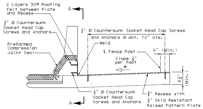
751.13.3.4 Sidewalk Details
PART SECTION THRU CENTER OF EXPANSION DEVICE
* See Structural Project Manager for direction of slope.751.13.3.5 Double Faced Median Barrier Bridge Curb
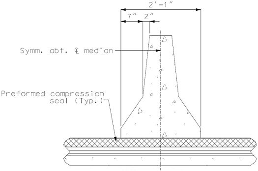 |
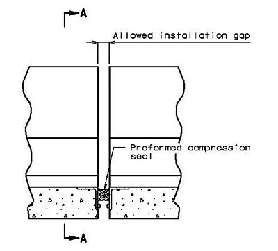 |
751.13.3.6 Drainage Details
Drainage details should be handled similar to drainage details for strip seal expansion joint system.
751.13.4 Strip Seal Expansion Joint System
751.13.4.1 General
When skew > 20° or/and movement normal to joint at RDWY surface >1.80” strip seal expansion joint systems may be used.
Skew ≤ 55°, with following limitation:
- Check maximum opening ‖ to RDWY at RDWY surface, W ≤ Allowed maximum opening limit
- Check minimum opening ‖ to RDWY at RDWY surface, W ≥ Required minimum opening
- Check racking limit, Wpmax to Joint ≤ Allowed limit.
- Racking shall be checked for maximum rise and maximum fall temperature from max. installation temp., min. installation temp. and 60°F.
- If racking is > allowed limit then adjust maximum and minimum installation temp. for specific job with SPM approval. (40° ≤ Installation Temperature ≤ 90°).
If W > Allowed maximum opening limit, then reduce Gmax and Mn as needed to achieve W within an allowable limit.
When preformed compression joint system or strip seal expansion joint system cannot be used, then use flat plate expansion joint system in accordance with EPG 751.13.5 Flat Plate Expansion Joint System or use finger plate expansion joint system in accordance with EPG 751.13.6 Finger Plate Expansion Joint System.
Where construction is staged and armor must be spliced,
- 1) ensure sufficient clearance between staged construction joints and joint in armor in order to allow clearance to make field connection splice, and
- 2) permanent joint seal should be continuous (not spliced) and not placed until after joint armor installation is complete, meaning total armor is in place.
If a 3” and a 4” strip seal gland work by design, each by the same manufacturer or different manufacturers, the smaller one could be preferred based on a lesser capacity for debris load, or the larger one based on an larger factor of safety. List both on the plans unless there is strong preferential reason to select one over the other.
Parallel movements (racking) shall be less than allowed racking limit for either rise or fall movements from installation temperature. Maximum skew shall be 55°.
Formulas:
- M = γ(ΔT)(α)(L), Bridge total movement or individual rise and fall movements
- ΔT = Corresponding temperature range
- L = Expansion length
- α = Coefficient of linear expansion
- γ = Load Factor
- M = Bridge movement parallel to RDWY for expansion length(s)
- Mn = M ⊥ = M cosθ : Movement perpendicular to joint
- M‖ = M sinθ or Mn tanθ : Movement parallel to joint, or racking
- θ = skew angle
Note: If minimum installation gap requirements do not meet then increase gap at 60°F or with SPM approval reduce installation temp. in 10°F increments until requirements are met for specific job. Report maximum and minimum installation temperature on the plans.
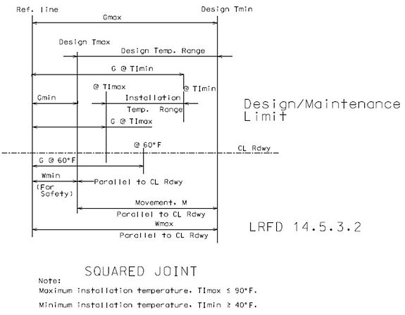
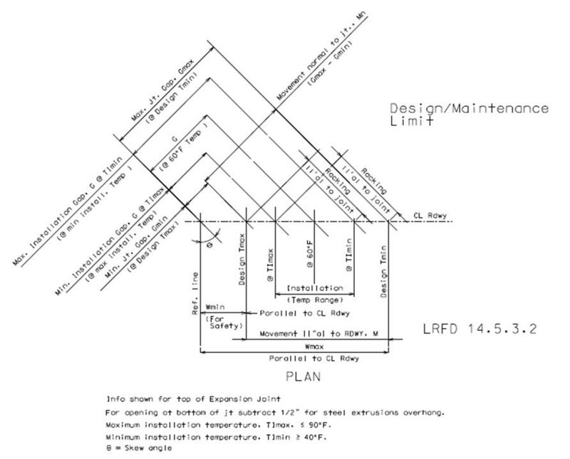
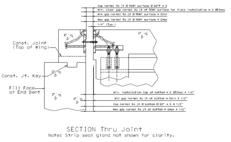
Notations:
Wmin = Minimum gap parallel to center line of RDWY at roadway surface
Wmax = Maximum gap parallel to center line of RDWY at roadway surface
G = Gap perpendicular to joint at RDWY surface at 60◦ temperature
Gmin @ Tmax = Minimum gap perpendicular to joint at RDWY surface at maximum design temperature
Gmax @ Tmin = Maximum gap perpendicular to joint at RDWY surface at minimum design temperature
G @ TImax = Minimum gap perpendicular to joint at RDWY surface at maximum installation temperature
G @ TImin = Maximum gap perpendicular to joint at RDWY surface at minimum installation temperature
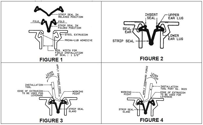
Acceptable installation procedure for strip seal joint system (copied from Watson Bowman Acme Brochure):
- Installation Procedure:
751.13.4.2 Strip Seal Expansion Joint System Summary
751.13.4.3 Strip Seal Expansion Joint System – Details
| Bridge Standard Drawings |
|---|
| Strip Seal Expansion Joint System |
751.13.4.4 Design Example, Strip Seal at End Bent
New steel structure, Expansion Length, L = 235 ft., skew θ = 30°
- Design temperature range -30° to 120° => Design Tmax = 120°F
- Design Tmin = -30°F
- Load factor, ɣ = 1.2
Step1: Find minimum installation gap normal to joint at maximum installation temperature = 90°F and minimum installation temperature = 40°F. Assume installation gap value at 60°F for new structure and modify value as needed to meet other requirements.
Gap normal to joint at 60°F installation temp. at RDWY surface, G = 2” assumed
Gap normal to joint at 60°F installation temp. at bottom of joint = G at 60°F + 2*0.25 = 2.5”
Compute gap normal to joint @ 10 degrees increment between min. and max. installation temp. and report on the plan details.
Gap normal to joint at max. installation temp. (90°F) at RDWY surface, G at Timax
- = G - (γ)(α)(90°F - 60°F)(L*12)(cosθ) = 1.43 ≤ 1.5” ∴ N.G.
Try Gap normal to joint at 60°F installation temp. at RDWY surface, G = 2 ¼”
Gap normal to joint at 60°F installation temp. at bottom of joint = G at 60°F + 2*0.25 = 2.75”
Compute gap normal to joint @ 10 degrees increment between min. and max. installation temp. and report on the plan details.
Gap normal to joint at max. installation temp. (90°F) at RDWY surface, G at Timax
- = G - (γ)(α)(90°F - 60°F)(L*12)(cosθ) = 1 11/16”
Gap normal to joint at 80°F installation temp. at RDWY surface, G at 80°F
- = G - (γ)(α)(80°F - 60°F)(L*12)(cosθ) = 1 7/8”
Gap normal to joint at 70°F installation temp. at RDWY surface, G at 70°F
- = G - (γ)(α)(70°F - 60°F)(L*12)(cosθ) = 2 1/16”
Gap normal to joint at 50°F installation temp. at RDWY surface, G at 50°F
- = G + (γ)(α)(60°F – 50°F)(L*12)(cosθ) = 2 7/16”
Gap normal to joint at min. installation temp. (40°F) at RDWY surface, G at Timin
- = G + (γ)(α)(60°F – 40°F)(L*12)(cosθ) = 2 5/8”
Min installation gap normal to joint = 1 11/16” ≥ 1.50” min. req’d gap normal to joint. ∴ O.K.
Step 2: Find minimum and maximum gap normal to joint and parallel to RDWY at maximum and minimum design temperature. Find movement normal to joint and parallel to RDWY.
- Information at RDWY surface (Edge of armor to edge of armor)
- M ‖’al to RDWY, M = γ(∝)(design temperature range)(L x 12) = 3.30"
- M ⊥ to the joint, Mn = M * cos(θ) = 2.85”
- Gap normal to joint at 60°F temp., G = 2.25”, = 1.2 and Steel armor overhang = 0.25”
- Minimum joint gap (maximum closure normal to joint at Design Tmax), Gmin
- = G - (γ)(α)(Design Tmax - 60°F)(L*12)(cosθ)
- =1.11” ≥ 0.5” ∴ O.K.
Minimum opening ll’al to RDWY, Wmin = 1.11/(cosθ) = 1.28” ≥ 0.5” ∴ O.K. Maximum joint gap (Maximum opening normal to joint at Design Tmin), Gmax = G + ( ) (α)( 60°F - Design Tmin)(L*12)(cos θ) = 3.96” Maximum opening ‖’al to RDWY, Wmax = 3.96/(cosθ) = 4.58” ≥ 4” ∴ N.G.unless SPM approve 5"
With SPM approve Wmax = 4.58” ≤ 5” ∴ O.K. with SPM approval Note: As per LRFD 14.5.3.2, Wmax ≤ 4”
M ⊥ to the joint, Mn = Gmax – Gmin = 3.96 – 1.11 = 2.85” (Match to previously computed value) ∴ O.K.
Movement ‖’al to RDWY, M = Wmax – Wmin = 4.58 - 1.28 = 3.30” (Match to previously computed value) ∴ O.K.
Step 3: Compare design requirements to manufacture Information (see strip seal summary) and determine all possible strip seal sizes which will meet the design requirements.
D.S. Brown allows L2 - 400 strip seal to open up to 4” normal to joint and up to 4” parallel to RDWY if racking is less than allowed racking limit = 2” and L2 - 500 strip seal to open up to 5” normal to joint and up to 5” parallel to RDWY if racking is less than allowed racking limit = 2”. Note: Max opening parallel to RDWY ≤ 4” preferred or 5” with SPM approval. Gmax and Wmax should be ≤ 4” for L2 – 400, and Gmax and Wmax should be ≤ 5” for L2 – 500. Note: Max opening parallel to RDWY, Wmax ≤ 4” preferred or 5” with SPM approval.
Gmax = 3.96” ≤ 4” ∴ O.K. Wmax = 4.58” ≥ 4” allowed for L2 – 400 ∴ L2-400 N.G.
Gmax = 3.96” ≤ 5” ∴ O.K. Wmax = 4.58” ≤ 5” allowed for L2 – 500 ∴ L2-500 may work, check racking
Watson Bowman Acme (Wabo) allows SE - 300 strip seal to open up to 3” normal to joint and up to 3”/cos(skew) parallel to RDWY if racking is less than allowed racking limit = 1.25”. Wabo allows SE - 400 strip seal to open up to 4” normal to joint and up to 4”/cos(skew) parallel to RDWY if racking is less than allowed racking limit = 1.25”. Wabo allows SE - 500 strip seal to open up to 5” normal to joint and up to 5”/cos(skew) parallel to RDWY if racking is less than allowed racking limit = 0.625”. Note: Max opening parallel to RDWY, Wmax ≤ 4” preferred or 5” with SPM approval.
Gmax ≤ 3” and Wmax should be ≤ 3”/cos(skew) for SE – 300, Gmax ≤ 4” and Wmax should be ≤ 4”/cos(skew) for SE – 400, and Gmax ≤ 5” and Wmax should be ≤ 5”/cos(skew) for SE – 500. Note: Max opening parallel to RDWY, Wmax ≤ 4” preferred or 5” with SPM approval.
Gmax = 3.96” ≥ 3” ∴ N.G. Wmax = 4.58 ” ≥ 3/(cosθ) = 3.46” allowed for SE – 300 ∴ SE-300 N.G.
Gmax = 3.96” ≤ 4” ∴ O.K. Wmax = 4.58” ≤ min((4/(cosθ) = 4.61”), 5”) allowed for SE – 400
- ∴ SE- 400 may work, check racking
Gmax = 3. 96” ≤ 5” ∴ O.K. Wmax = 4.58” ≤ min((4/(cosθ) = 4.61”), 5”) allowed for SE – 500
- ∴ SE- 500 may work, check racking
Step 4: Compare anticipated racking to allowed manufacturer racking limit.
Check racking (‖’al to joint) for max. design temperature & strip seal installation temp. range.
Racking for min. installation temp. case = γ(∝)(Design Tmax-TImin)(L x 12)(sin(θ))
- =1.2 * 0.0000065 * (120 – 40) * 240 * 12 * sin(θ)
- = 0.88”
Racking for max. installation temp. case = γ(∝)(Design Tmax-TImax)(L x 12)(sin(θ))
- =1.2 * 0.0000065 * (120 – 90) * 240 * 12 * sin(θ)
- = 0.33”
Racking for 60°F installation temp. case = γ(∝)(Design Tmax-T60)(L x 12)(sin(θ))
- =1.2 * 0.0000065 * (120 – 60) * 240 * 12 * sin(θ)
- = 0.66”
Maximum racking for max. design temperature case = 0.88”
Check Racking (‖’al to joint) for min. design temperature & strip seal installation temp. range
Racking for min. installation temp. case = γ(∝)(TImin-Design Tmin)(L x 12)(sin(θ)) = 1.2 * 0.0000065 * (40 – (-30)) * 240 * 12 * sin(θ) = 0.77” Racking for max. installation temp. case = γ(∝)(TImax-Design Tmin)(L x 12)(sin(θ)) = 1.2 * 0.0000065 * (90 – (-30)) * 240 * 12 * sin(θ) = 1.32” Racking for 60°F installation temp. case = γ(∝)(T60-Design Tmin)(L x 12)(sin(θ)) = 1.2 * 0.0000065 * (60 – (-30)) * 240 * 12 * sin(θ) = 0.99”
- Maximum racking for min. design temperature case = 1.32”
- Maximum racking for min. design temperature case and max. design temperature case = 1.32”
Compare anticipated racking to allowed manufacturer racking limit:
Anticipated max racking = 1.32 > 1 ¼” racking allowed for Wabo SE- 400 ∴ N.G.
Anticipated max racking = 1.32 > 5/8” racking allowed for Wabo SE- 500 ∴ N.G.
Anticipated max racking = 1.32 ≤ 2” racking allowed for D S Brown L2- 500 ∴ Racking is O.K.
Show on the Plans:
| Manufacturer | Strip Seal System (Designated Name) |
Movement Parallel to RDWY |
① Allowed Installation Gap Normal to Joint @ RDWY Surface @ Air/Surface Temperature 1 |
2 | |||||
|---|---|---|---|---|---|---|---|---|---|
| @ 40°F | @ 50°F | @ 60°F | @ 70°F | @ 80°F | @ 90°F | ||||
| D.S. Brown (EPDM Joint Seal) | Strip seal L2 - 500 | 3 5/16” | 2 5/8” | 2 7/16” | 2 1/4” | 2 1/16” | 1 7/8” | 1 11/16” | ☐ |
| ① See Bridge Standard Drawings. | |||||||||
| 1 The installation temperature shall be taken as the actual air temperature averaged over the 24-hour period immediately preceding installation. | |||||||||
| 2 MoDOT Construction personnel will indicate the strip seal expansion joint system installed. | |||||||||
Try Design Example 1 with reduced installation temperature:
Use maximum installation temperature 80°F instead of 90°F with SPM approval and recheck racking.
- Gap normal to joint at 80°F installation temp. at RDWY surface, G at 80°F
- = G - (γi)(α)(80°F - 60°F)(L*12)(cosθ) = 1.87” = 1 7/8” ≥ 1.50” min. req’d gap normal to joint ∴ O.K.
Racking:
Check Racking (‖’al to joint) for max. design temperature & strip seal installation temp. range.
Racking for min. installation temp. case = γ(∝)(Design Tmax-TImin)(L x 12)(sin(θ)) =1.2 * 0.0000065 * (120 – 40) * 240 * 12 * sin(θ) = 0.88” Racking for max. installation temp. case = γ(∝)(Design Tmax-TImax)(L x 12)(sin(θ)) =1.2 * 0.0000065 * (120 – 80) * 240 * 12 * sin(θ) = 0.44” Racking for 60°F installation temp. case = γ(∝)(Design Tmax-T60)(L x 12)(sin(θ)) =1.2 * 0.0000065 * (120 – 60) * 240 * 12 * sin(θ) = 0.66” Maximum racking for max. design temperature case = 0.88”
Check Racking (‖’al to joint) for min. design temperature & strip seal installation temp. range
Racking for min. installation temp. case = γ(∝)(TImin-Design Tmin)(L x 12)(sin(θ))
- = 1.2 * 0.0000065 * (40 – (-30)) * 240 * 12 * sin(θ)
- = 0.77”
Racking for max. installation temp. case = γ(∝)(TImax-Design Tmin)(L x 12)(sin(θ))
- = 1.2 * 0.0000065 * (80 – (-30)) * 240 * 12 * sin(θ)
- = 1.21”
Racking for 60°F installation temp. case = γ(∝)(T60-Design Tmin)(L x 12)(sin(θ))
- = 1.2 * 0.0000065 * (60 – (-30)) * 240 * 12 * sin(θ)
- = 0.99”
Maximum racking for min. design temperature case = 1.21”
- Maximum racking for min. design temperature case and max. design temperature case = 1.21”
Compare anticipated racking to allowed manufacturer racking limit:
Anticipated max racking = 1.21 ≤ 1 ¼” racking allowed for Wabo SE- 400 ∴ Racking is O.K.
Anticipated max racking = 1.21 > 5/8” racking allowed for Wabo SE- 500 ∴ N.G.
Anticipated max racking = 1.21 ≤ 2” racking allowed for D S Brown L2- 500 ∴ Racking is O.K.
Show on the Plans:
| Manufacturer | Strip Seal System (Designated Name) |
Movement Parallel to RDWY |
① Allowed Installation Gap Normal to Joint @ RDWY Surface @ Air/Surface Temperature 1 |
2 | |||||
|---|---|---|---|---|---|---|---|---|---|
| @ 40°F | @ 50°F | @ 60°F | @ 70°F | @ 80°F | @ 90°F | ||||
| Watson Bowman Acme (Wabo) | Strip seal SE - 400 | 3 5/16” | 2 5/8” | 2 7/16” | 2 1/4” | 2 1/16” | 1 7/8” | N/A3 | ☐ |
| D.S. Brown | Strip seal L2 - 500 | 3 5/16” | 2 5/8” | 2 7/16” | 2 1/4” | 2 1/16” | 1 7/8” | 1 11/16” | ☐ |
| ① See Bridge Standard Drawings. | |||||||||
| 1 The installation temperature shall be taken as the actual air temperature averaged over the 24-hour period immediately preceding installation. | |||||||||
| 2 MoDOT Construction personnel will indicate the strip seal expansion joint system installed. | |||||||||
| 3 N/A = Installation is not allowed at this temperature. | |||||||||
Note: For strip seal expansion joint system at intermediate bent compute gaps and movements from right side and left side expansion length using appropriate temperature range and thermal coefficient based on superstructure material.
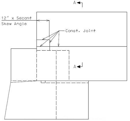
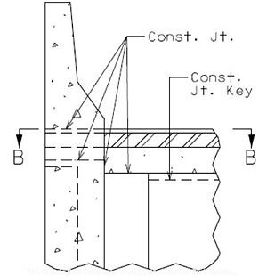
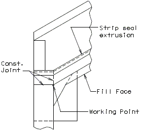
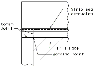
751.13.4.5 Barrier Curb Details
Barrier Curb at End Bents
 |
 |
 |
 |
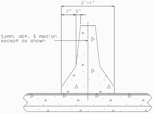
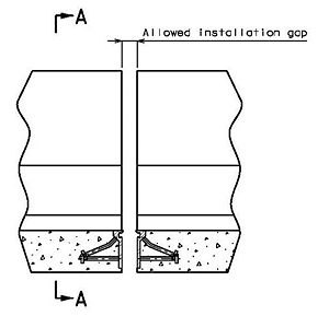
751.13.4.6 Double Faced Median Barrier Curb Details
For details not shown of median barrier bridge curb, see the safety barrier curb details, Design Division Standard Plans (Concrete Median Barrier) and Bridge Design Layout.
 |
 |
751.13.4.7 Drainage Details
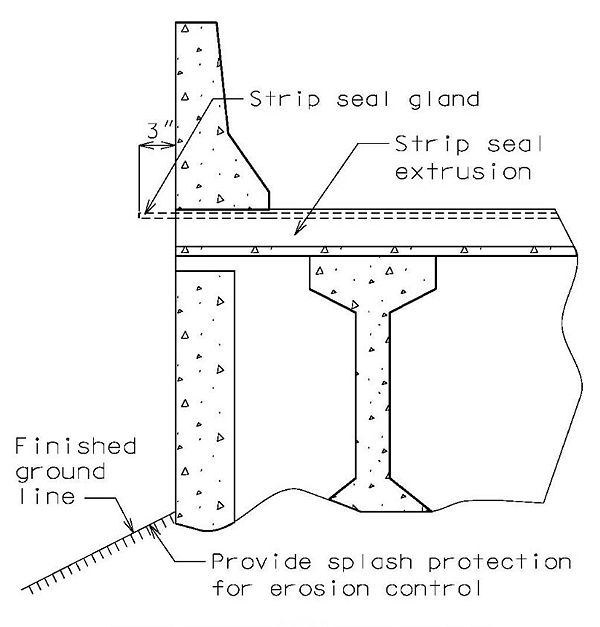
In order for strip seal expansion joint systems to function properly, the gland shall be allowed to drain to prevent build-up of debris. Debris may punch holes in the gland and the extra load may possibly pull the gland from the extrusions.
To prevent debris buildup on the strip seals the gland should not be turned up at the barrier curb. Instead, the steel armor with extrusions should be extended to the face of the slab through the barrier curb.
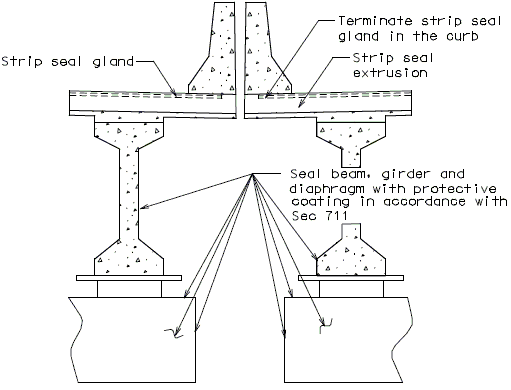
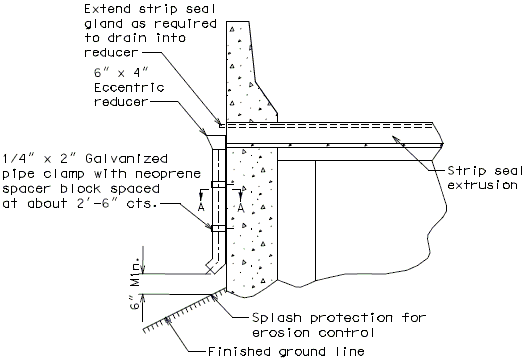
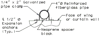
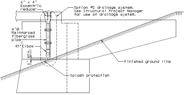
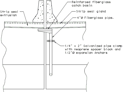
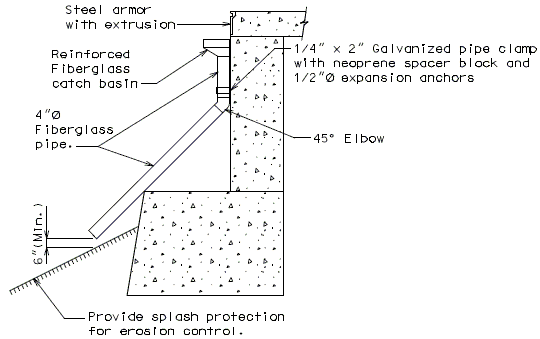
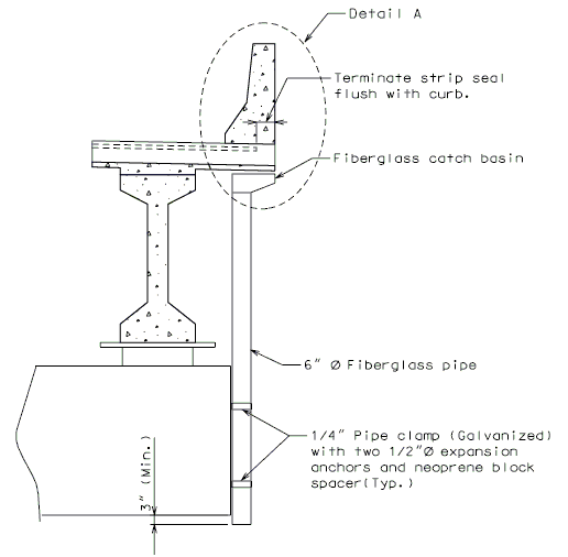
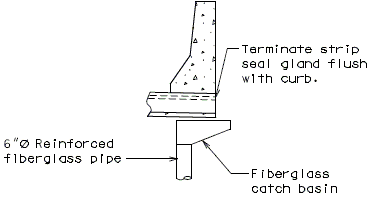
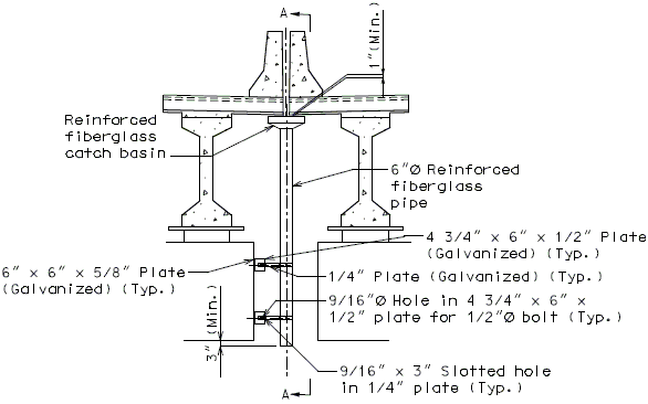
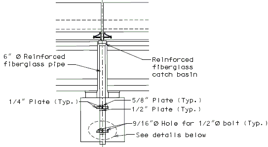
Drainage shall be handled by one of two methods. The first method is to let the water run off the gland and free fall to the ground below. The gland should extend past the edge of slab 3 inches minimum. At intermediate bents, the bent cap should have a protective coating applied to prevent moisture saturation of the concrete. On structures where there is an adjacent structure separated by a median barrier curb with an open joint (Type D or Split Median) the gland should be terminated at some point under the curb at all bent types and protective coating should be applied at all faces exposed to moisture. The second method of drainage is to provide a fiberglass pipe drainage system to collect water at the bents.
See the Structural Project Manager for the method of drainage to be used.
The following pages provide some possible details that may be used for strip seal expansion joint drainage systems.
If the fiberglass pipe drainage system is used, payment will be made under the pay item. Drainage System (On structure), Lump Sum.
Option #1- No Drainage System, at End Bent
Option #1- No Drainage Sytem, at Split Median Barrier Curb at Intermediate Bent
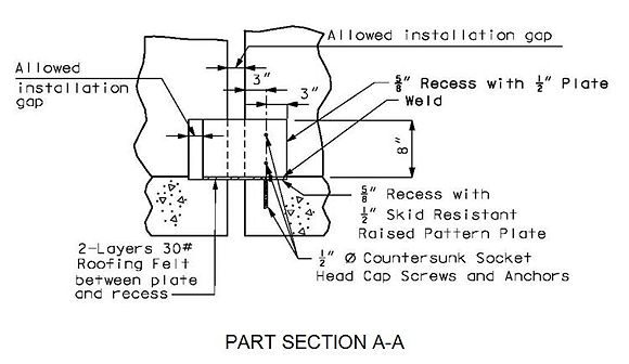
Option #2 - One-Piece Drain System at End Bent
FRONT ELEVATION
PART SECTION A-A
SIDE ELEVATION
Option #2 - One-Piece Drain System, Split Median Barrier Curb at End Bent
FRONT ELEVATION
SECTION THRU BENT
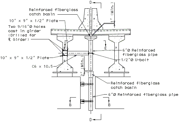
Option #2 - One-Piece Drain System, Intermediate Bent
DETAIL A
(Optional)
Option #2 - One-Piece Drain System at Split Median Barrier Curb at Intermediate Bent
SECTION THRU JOINT
Note: If dropping water to ground from bottom of beam is not allowed, an additional pipe system shall be used.
SECTION A-A
Option #3 - Three-Piece Drain System at Split Median Barrier Curb at Intermediate Bent
SECTION THRU JOINT
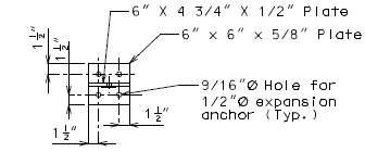
SECTION B-B
SECTION C-C
SECTION D-D
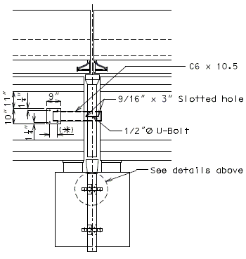
(*)Varies (Space holes to clear B1 bars in P/S girders. Use 6" for plate girders.)
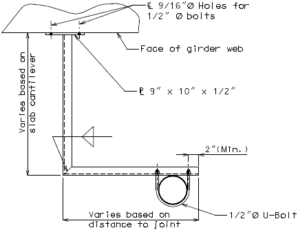
SECTION E-E
751.13.4.8 Polymer Concrete
Strip Seal Expansion Joint System may be used on rehabilitation projects where other expansion devices need to be replaced. Consult with Structural Project Manager about the use of polymer concrete with strip seals. Strip seal is to be designed with the same requirements as a normal strip seal expansion joint system.
- Note: Anchorage system shall be welded to strip seal steel armor with appropriate weld to meet AASHTO Fatigue for connection.
- Note: A pay item exists for this type of expansion joint system. The system will be paid for under Strip Seal Expansion Joint System per linear foot. Polymer Concrete will be paid for under Polymer Cocrete per cubic foot.
DETAIL OF SHEAR CONNECTOR
(Alternate #4 reinforcing bar shall be bent similarly)751.13.5 Flat Plate Expansion Devices
751.13.5.1 General
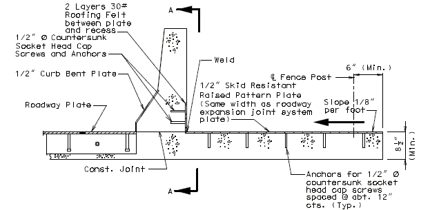
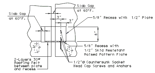
Flat Plate Expansion Joint System (FLPEJS) should not be used for new bridges. FLPEJS may be considered for rehabilitation jobs, for example if replacing similarly although not required. Significant truck traffic is a special challenge for flat plate expansion devices in service. FLPEJS may be considered for special situations when agreed upon by both the District Bridge Engineer and Bridge Division.
Finger Plate Expansion Joint System is recommended instead of FLPEJS where strip seals cannot be used due to large expansion lengths, curvature, skews over 55˚, or other design limitations.
The installation width, sub-surface gap = 3 1/2 in. is based on a design installation temperature of 60˚F.
Design movement for Flat Plate Expansion Devices is limited by the following criteria:
- 1. Full closure of surface gap.
- 2. Min. sub-surface gap = 1 in. (⊥ to joint)
- 3. Min. plate overlap = 1 1/2 in. (⊥ to joint)
- Note: Criterion 3 controls for standard details for both concrete and steel superstructures. Originally, the details for EPG 751.13.5 used a 3/4 in. x 7/8 in. bar, that allowed for a 2 ½ in. gap contraction (⊥ to joint). Functionally, the 3/4 in. x 7/8 in. bar is preferred but it is not available domestically as of July 2010. A 7/8 in. x 7/8 in. bar is shown as the standard in EPG 751.13.5 primarily due to domestic availability.
Flat Plate expansion devices can be used bridges of any skew.
| Maximum Expansion Length1 | ||
|---|---|---|
| Skew | Concrete Bridge | Steel Bridge |
| 0° | 496 ft. | 356 ft. |
| 10° | 504 ft. | 362 ft. |
| 20° | 528 ft. | 379 ft. |
| 30° | 573 ft. | 411 ft. |
| 40° | 648 ft. | 465 ft. |
| 50° | 772 ft. | 554 ft. |
| 60° | 992 ft. | 712 ft. |
| 1 This table is applicable for standard details found in EPG 751.13.5 and for joints where movement is expected from one side of the joint. When movement is expected from both sides of the joint, the sum of the expansion lengths participating at a joint should not exceed the values in this table. When larger expansion lengths are required, the surface gap, sub-surface gap and flat plate dimensions shall be determined by design. | ||
The max. surface gap requirement, W ≤ 4 in. is not considered for flat plate expansion devices since the surface gap neither impairs the riding characteristics of the roadway, nor damages vehicles nor destroys the function of the joint.
Dimensions shown are perpendicular to centerline of joint and do not vary with skew.
Part longitudinal sections for bridges on grades or verticle curves having a plate type intermediate expansion device shall be detailed with the expansion plate anchor to the long span side. If equal spans, then place expansion plate anchor on the high side. For bevel plate and permissible field splice details, see Bridge Standard Drawings.
Slotted wells in prestressed girders shall be located and shown on plans as between reinforcement bars or WWF.
Use bevel plate at end bents only when the grade of the slab is 3.0% or more. Modify the roadway plate, the 5/8 in. vertical plate and the continuous bar when the bevel plate is required.
751.13.5.2 Plan of Beam at Bearings

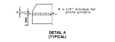
| Dimension R for Wide Flange Beams | ||||||
|---|---|---|---|---|---|---|
| Nominal Flange Width* |
8 ¼" | 9" | 10" | 10 ½" | 11 ½" | 12" |
| R | 0.54" | 0.54" | 0.64" | 0.70" | 0.75" | 0.80" |
| * For wide flange beams with flange widths other than those shown refer to AISC Steel Construction Manual for Dimension R. | ||||||
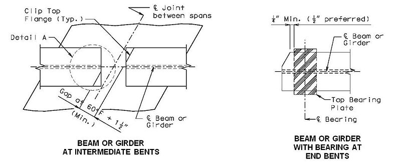
* Details shown above are for a steel structure, details for a prestressed structure are similar.
751.13.5.3 Miscellaneous Details
TYPICAL SIDEWALK DETAILS
TYPICAL MEDIAN DETAILS
PART SECTION A-A
751.13.5.4 Flat Plate Expansion Devices - Details
| Bridge Standard Drawings |
| Flat Plate Expansion Devices |
751.13.6 Finger Plate Expansion Devices
751.13.6.1 General
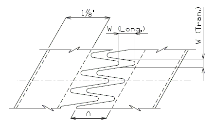
The max. roadway surface gap (W) shall meet the following criteria:
When W(Long.) < 8", Then W(Tran.) < 3".
OR
When W(Long.) > 8", Then W(Tran.) < 2".
The min. finger overlap = 1.5"
Expansion lengths are calculated from the total movement value by the following equation:
Expansion length =
Where:
| Max. Length of Expansion, ft. (1) | Total Movement, inches | Gap at 60° F, inches | |
|---|---|---|---|
| Concrete | Steel | ||
| 385 | 284 | 4 | 2 3/4 |
| 578 | 427 | 6 | 3 1/2 |
| 1 Longer expansion lengths are possible but they must be designed. | |||
For Concrete:
= 0.000006 ft/ft/˚F
= 120˚F
For Steel:
= 0.0000065 ft/ft/˚F
= 150˚F
751.13.6.2 Details at Bents
Details of Fingers
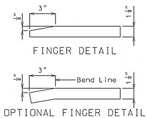
Details at End Bent
Dimensions shown are perpendicular to centerline of joint and do not vary with skew (Unless otherwise noted).
PART SECTION THRU EXPANSION DEVICE
(Steel Structure)
 |

|
| DETAIL "A" |
PART SECTION THRU EXPANSION DEVICE
(Prestress Structure)
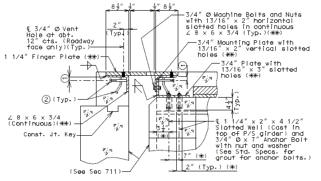
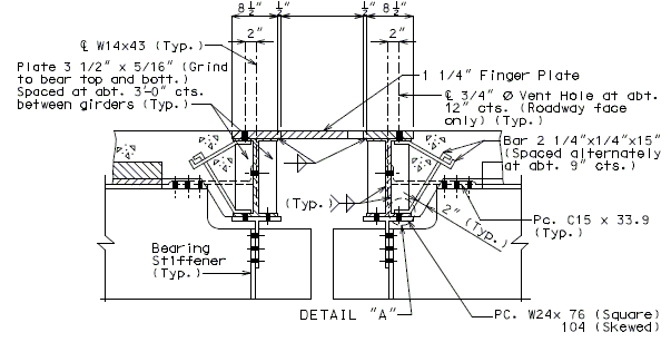
(*) Dimension along centerline of girder.
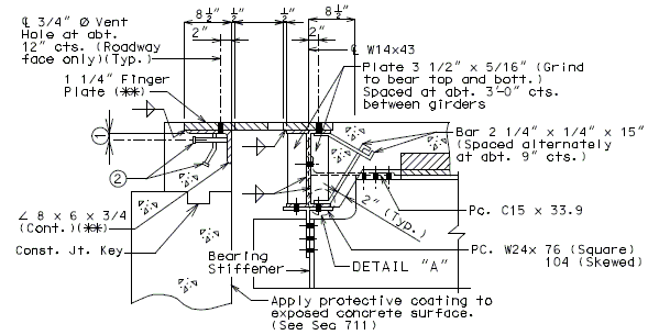
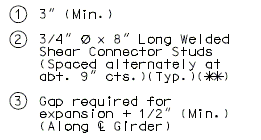
(**) When distance "A" or "D" shown in EPG 751.13.6.3 Typical Plan of Plate is greater than 9" or 12", respectively, then the details of supporting angles, mounting plates, shear studs and finger plate thickness need to be specially designed. Mounting Plates shall not be less than supporting angle in thickness.
Details at Intermediate Bent
Dimensions shown are perpendicular to centerline of joint and do not vary with skew (Unless otherwise noted).
PART SECTION THRU EXPANSION DEVICE
(Steel Structure)
Note: For Detail "A", see above.
PART SECTION THRU EXPANSION DEVICE
(Prestressed Structure)
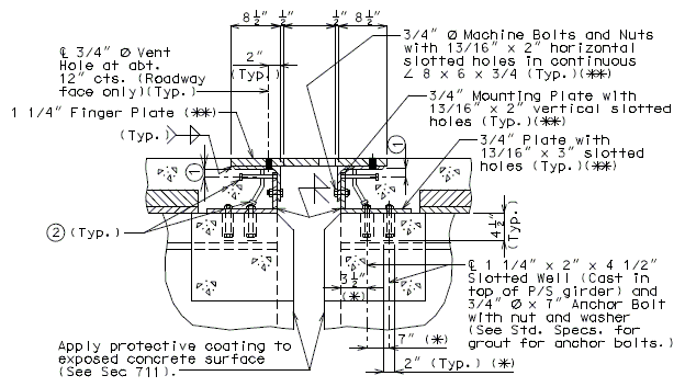
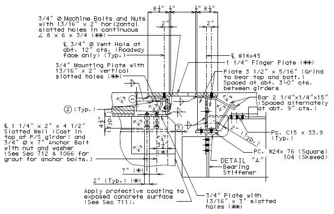
(*) Dimension along centerline of Girder.
(**) When distance "A" or "D" shown in EPG 751.13.6.3 Typical Plan of Plate is greater than 9" or 12", respectively, then the details of supporting angles, mounting plates, shear studs and finger plate thickness need to be specially designed. Mounting Plates shall not be less than supporting angle in thickness.
Dimensions shown are perpendicular to centerline of joint and do not vary with skew (Unless otherwise noted).
(*) Dimension along centerline of Girder.
(**) When distance "A" or "D" shown is greater than 9" or 12", respectively, then the details of supporting angles, mounting plates, shear studs and finger plate thickness need to be specially designed. Mounting Plates shall not be less than supporting angle in thickness.
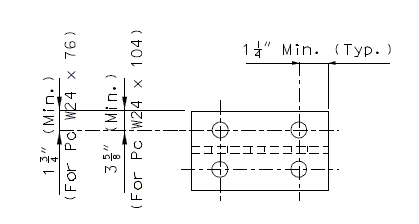
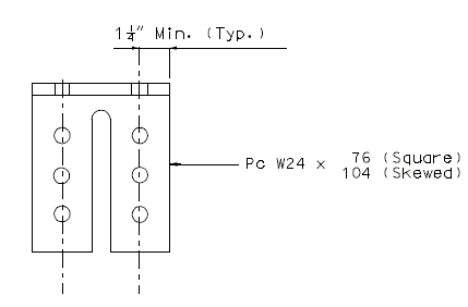
Details of W24 Piece
PLAN
| ELEVATION OF PIECE W24 X | 76 (SQUARED) |
| 104 (SKEWED) |
Note:
Place the above details near "Part Section Thru Expansion Joint System For Finger Plates".
All holes shown for connections to be subpunched 11/16" Ø (shop or field drill) and reamed to 13/16" Ø in field.
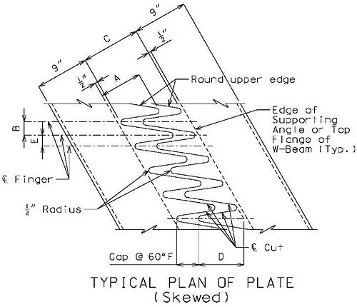
751.13.6.3 Typical Plan of Plate
- Squared Devices
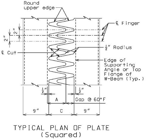
- A = 7.5" for 4" movement
- A = 9.5" for 6" movement
- C = A - 0.5" + Gap @ 60° F
- = skew angle
- C = (A - 0.5") + (Gap @ 60°F) cos
- D = (A- 0.5") sec
- E = 4" - B
751.13.6.4 Slab Details
The slab extension beyond the edge of the supporting member shall be shown on the plan of slab.
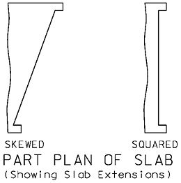
Additional slab bars shall be located in the slab extensions.
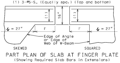 |
| ||||||||||||||||||||||
Where:
- = skew angle
- A = length of individual finder (previous section)
- 3.845" = and 4.095" = + 0.25"
- bf = 7.995", tw = 0.305" (W14x43)
- 0.25" = 0.5" plate overhang divided by two
- (The other overhang is included in Dimension A.)
On the plans the dimensions of the slab extension and the additional slab bars shall be specified on the plan of slab sheet where a special detail similar to the above detail may be used.
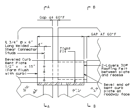
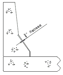
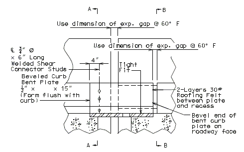
751.13.6.5 Barrier Curb Details
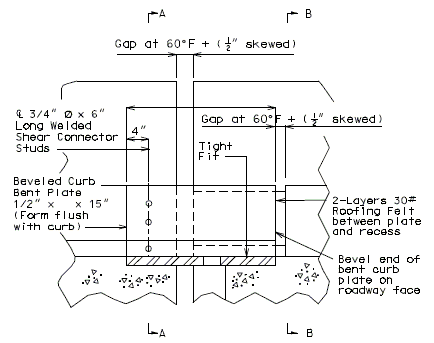
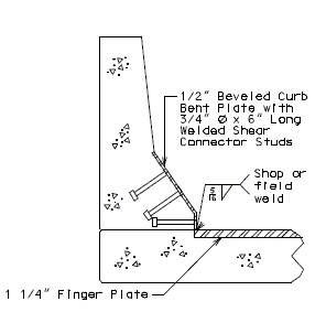
The R5 bar shall be used in the slab extension where there is insufficient clearance for the typical R4 bar.

The R5 bars shall be specified on the elevation of barrier sheet in a section detail.
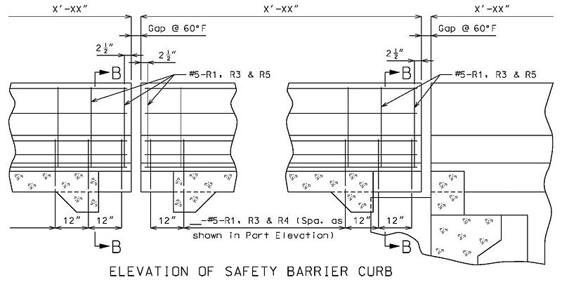
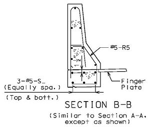
 |
|
| PART ELEVATION OF BARRIER CURB (END BENT) |
TYPICAL PART SECTION A-A |
 |
|
| PART ELEVATION AT END OF BEVELED CURB BENT PLATE |
SECTION C-C |
 |
|
| PART ELEVATION OF BARRIER CURB (INTERMEDIATE BENT) |
TYPICAL PART SECTION B-B |
PART PLAN OF CURB AT END BENT (SQUARE)
PART PLAN OF CURB AT END BENT (SKEWED)
PART PLAN OF CURB AT INTERMEDIATE BENT (SQUARE)
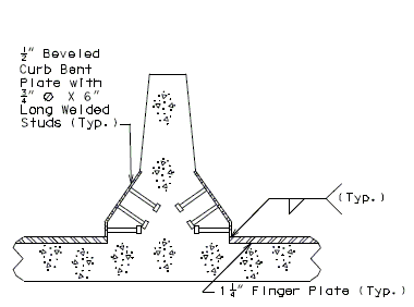
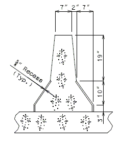
751.13.6.6 Median Barrier Curb Details
For the details not shown of median barrier bridge curb, see the safety barrier curb details. The Design Division Standard Plans (Concrete median barrier ), and the Bridge Design Layout.
 |
| ||||
| TYPICAL PART SECTION A-A | TYPICAL PART SECTION B-B | ||||
 |
| ||||
| PART ELEVATION OF BARRIER CURB (INTERMEDIATE BENT) |


