903.2 Extent of Signing: Difference between revisions
m →903.1.4 Sign Function and Purpose (MUTCD Section 2A.01): article construction |
→Table 903.1.18.2 Common Uses of Sign Background Colors: Flourescent yellow sheeting (instead of yellow) will now be used |
||
| Line 522: | Line 522: | ||
!style="background:#BEBEBE" colspan="10"|Background | !style="background:#BEBEBE" colspan="10"|Background | ||
|- | |- | ||
!style="background:#BEBEBE"|Black!!style="background:#BEBEBE"|Blue!!style="background:#BEBEBE"|Brown!! style="background:#BEBEBE"|Green!!style="background:#BEBEBE"|Orange!!style="background:#BEBEBE"|Red !!style="background:#BEBEBE"|White!!style="background:#BEBEBE"|Yellow!!style="background:#BEBEBE"|Flourescent Yellow-Green!!style="background:#BEBEBE"|Flourescent Pink | !style="background:#BEBEBE"|Black!!style="background:#BEBEBE"|Blue!!style="background:#BEBEBE"|Brown!! style="background:#BEBEBE"|Green!!style="background:#BEBEBE"|Orange!!style="background:#BEBEBE"|Red !!style="background:#BEBEBE"|White!!style="background:#BEBEBE"|Flourescent Yellow!!style="background:#BEBEBE"|Flourescent Yellow-Green!!style="background:#BEBEBE"|Flourescent Pink | ||
|- | |- | ||
|Regulatory||X||-||-||-||-||X||X||-||-||- | |Regulatory||X||-||-||-||-||X||X||-||-||- | ||
Revision as of 13:16, 20 October 2009
The extent of signing by contract on any project is determined early in the project scope. Structural guide signs and supports (overhead or ground-mounted) are paid for by contract, regardless of the type of facility. Sheet signs and supports are supplied by contract for all route classifications and project conditions. Unless otherwise agreed to among departments or divisions, the following are general guidelines for the extent of contract signing.
| LED Signal |
| Report 2000 |
| See also: Innovation Library |
Regulatory and warning signs should be used conservatively because these signs tend to lose effectiveness if they are used to excess. If used, route signs and directional signs should be used frequently because they promote reasonably safe and efficient operations by keeping road users informed of their location.
903.1.1 Signing on Interstates, Freeways and Expressways with Full Access Control
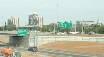
Complete signing (structural and sheet signs, supports, delineators, etc.) is provided by contract for these roadways and all directly affected side roads, interchanges or intersections.
903.1.2 Signing on Urban Projects
Structural ground-mounted or overhead guide signs and supports are supplied by contract. Delineators, when specified, are furnished and installed by contract.
903.1.3 Signing on Rural Projects
Structural overhead and ground-mounted guide signs and sign supports are supplied by contract. When an interchange is within the limits of a rural project, route markers, guide, regulatory and warning signs within the interchange limits are supplied by contract. Delineators, when specified, are furnished and installed by contract.
903.1.4 Sign Function and Purpose (MUTCD Section 2A.01)

Support. The functions of signs are to regulate, warn and guide road users. Both words and symbols are used to convey the messages. Signs are not typically used to confirm rules of the road. Detailed sign requirements are available for regulatory signs, warning signs, guide signs (conventional roads), guide signs (Freeways and Expressways), specific service (LOGO) signs, tourist-oriented direction signs, recreational and cultural interest area signs, emergency management signs, typical applications and sign supports.
Signing of all interstate highways is coordinated on a national basis by the MUTCD and the Standard Highway Signs Manual. Signing of highways other than the interstate system is coordinated on a statewide basis by MoDOT and the MUTCD.
Standard. Because the requirements and standards for signs depend on the particular type of highway upon which they should be used, the following definitions shall apply:
Freeway - a divided state highway in which access is provided solely through interchanges at crossroads and streets rather than at grade intersections;
Expressway - a divided state highway in which access may be provided through interchanges at crossroads and streets or at-grade intersections; and
Conventional Route—a state highway that is neither a freeway nor an expressway.
Any exceptions or requests for a regulatory or warning sign, or any sign for use on the Interstate system not described in this article shall be submitted to the State Traffic Engineer for consideration.
Special signs or special use of a sign that is not regulatory or warning, or any sign intended for use on the Interstate system shall be used at the district engineer’s discretion. If the special sign is not compliant with the MoDOT sign policy the sign shall not be funded from Central Office budget.
The provisions of the MUTCD shall be followed for all special signs.
Guidance. When a special sign is approved by district discretion, consideration should be given to any statewide implication from the sign, cost to the state and the precedence the sign may set. Advise Traffic of any special signing approved by the districts so that this information can be shared with other districts. This will provide a basis for other districts when considering similar requests.
903.1.5 Standardization of Application (MUTCD Section 2A.03)
Support. Urban traffic conditions differ from rural conditions and in many instances signs are applied and located differently. Where pertinent and practical, this Manual sets forth separate recommendations for urban and rural conditions.
Guidance. Signs should be used only where justified by engineering judgment or studies. Results from traffic engineering studies of physical and traffic factors should indicate the locations where signs are deemed necessary or desirable.
Roadway geometric design and sign application should be coordinated so that signing can be effectively placed to give the road user any necessary regulatory, warning, guidance, and other information.
Standard. Each standard sign shall be displayed only for the specific purpose as prescribed in this article. Determination of the particular signs to be applied to a specific condition shall be made according to the criteria set forth in this article. Before any new highway, detour or temporary route is opened to traffic, all necessary signs shall be in place. Signs required by road conditions or restrictions shall be removed when those conditions cease to exist or the restrictions are withdrawn.
903.1.6 Excessive Use of Signs (MUTCD Section 2A.04)
Guidance. Regulatory and warning signs should be used conservatively because if these signs are used to excess their effectiveness tends to be lost. If used, route signs and directional signs should be used frequently because they promote reasonably safe and efficient operations by informing travelers of their location.
903.1.7 Extent of Contract Payments (MUTCD Section 2A.04a)
Standard. All structural guide signs and supports (overhead or ground mounted) are paid by contract, regardless of the type of facility. All sheet signs and supports are supplied by contract for all route classifications and project conditions. Exceptions shall be made only by agreement among departments or divisions.
903.1.8 Plan Development Procedure (MUTCD Section 2A.04b)
Standard. The preparation of signing plans requires the cooperation and coordination between district Maintenance, Traffic and Design.
When using preexisting structures to accommodate larger new signs, consideration shall be given to the dimensions and load capacity of the existing structure. The larger signs must properly fit on the existing structure and not exceed the structure’s design capacity.
When the need arises to modify the legend of a sign not built to current standards, the entire sign shall be replaced.
Guidance. Bridge is to be consulted for mounting signs directly on bridges and other structures, special truss designs and bridge- or wall-mounted trusses.
Sign visibility from a distance is critical. Sign locations should be coordinated with other design features that include, but are not limited to bridges, highway lighting, traffic signals, drainage structures, overhead utilities, underground utilities and horizontal and vertical alignments that decrease sign visibility.
The district should prepare proposed sign locations and review the plans for standards and quality control.
When the sign is mounted on a truss, all signs on the truss not built to current standards should be replaced after considering the age, future conditions and detail of the sign.
It is recommended that all signs, which do not follow standard designs, be identified. Non-standard signs should be justified.
For preliminary discussions, only the sign location plan showing existing and proposed signing is recommended. Sign details, cross-sections, tabulation sheets, computer generated sign designs or other detailed information should not be completed at this time. Once the preliminary location plan is agreed on, the district is to prepare special sign detail sheets (D-31), forms D-29 and D-30 (see Figure 903.1.12.1), truss data sheets and template cross-sections for trusses and ground mounted signs. Truss cross-sections should not be drawn on the same sheets as ground mounted sign cross-sections. The districts are responsible for accuracy of the preliminary and final detail design.
The district finalizes the plans and is to submit them to Design with the roadway plans, or as a separate project if so programmed. The districts are responsible for accuracy and completeness of plans. Typical signing location plans for interchanges are shown in 903.13, Typical Signing Applications. Design Division is available for consultation during any part of the plan preparation process.
A Sign Design Order Form (Design Form D-28) should be completed for all and sent to Traffic as soon as the signs are identified.
Preliminary layouts of special signs should be submitted along with the completed D-28 form to Traffic so the final design can be produced using SignCAD. This program incorporates MoDOT standards and generates an output sheet that can be inserted into the plans. All special signs should be designed according to the dimensional data shown in the Standard Highway Signs manual, standard plans, MUTCD, standard specifications and this article. Traffic should review all signs.
The legend of a sign with L-2 (demountable) or L-4 (button) copy should not be modified. These signs should be replaced. Any signs originally fabricated with a baked enamel background (STB type) should be replaced.
If an existing truss with luminaires is provided with new signs, consideration is to be given to shutting off the power and removing the luminaires due to the high reflectivity of structural sign sheeting.
Option. Design or Traffic may provide comments on the preliminary layout at the district's request. It is suggested that districts form review teams from various departments to review plans at the preliminary layout stage, and at final design. After the district reviews plans, Design Division may be consulted for review at the district's discretion.
Larger plan scales, like 1 in. = 50 ft. (1:500), may be used if necessary to show complex interchanges or intersections with numerous signs.
Two or more segments of alignment may be shown on one sheet. For ease of design, review and construction, sign locations for interchanges are completely shown on one sheet.
Support. Location plans show the proposed pavement geometrics, the sign location, sign number, station, width and height, sign code (if applicable) and special or standard legend on standard 22 in. x 34 in. sheets drawn to a scale of 1 in. = 100 ft. (1:1000) or 1 in. = 200 ft. (1:2000). Sign sizes are shown as width x height, in feet and/or inches for sheet signs, and in feet only for structural signs. Tabulated removals and general information is show for existing signs. The standard sign code (i.e. R3-1a, W10-1, etc.) is shown for signs found in the Standard Highway Signs manual or standard plans.
Signs are numbered in a logical order. Existing signs, which should be removed or remain in place, are not numbered. Multiple signs on a single mount are further indicated with lower case letters (i.e. 45(a), 45(b), 45(c)). If signs are added or deleted at a later date, renumbering all signs is not required. If signs are added, signs may be numbered 43, 43A, 43B, etc., or the next highest sign number may be used. If signs are deleted, a general note listing voided signs is provided.
Existing signs are shown with dashed lines and are listed as a removal item where appropriate. Existing signs to be relocated to new posts and new signs on existing posts are numbered and noted as such. Existing signs in poor condition should be replaced. In complex areas where many signs should be replaced, proposed signing and existing signing may be shown separately on different plan sheets to avoid clutter and plan confusion; however, combined is preferred, if possible.
When replacing signs for many miles of roadway to be let in sections, it is desirable to generate an overall sign location plan to coordinate guide sign placement through numerous projects. For this situation it is not necessary to show signs other than guide signs. It is recommended to show the limits of each project on this location plan. Signs are identified as truss, bridge- or ground-mounted or as strapped to a signal post or column. If applicable, truss type (cantilever, span, butterfly) and location are shown. Whether the truss is box or tubular does not need to be noted on preliminary location plan, but is shown on the final plan. A standard legend identifying symbols is used to alleviate crowding on plans. Typical location plans at interchanges are shown in 903.13, Typical Signing Applications.
Truss pedestals are not placed in gore areas or other areas that have high exposure to traffic.
A number of standard signs are detailed in Standard Highway Signs and in the standard plans. Special sign detail sheets are not required for signs detailed in these references.
When staged projects are scheduled in unison or closely together, complete signs are provided with the inappropriate legend covered until needed. Legends to be covered are noted on the plans, and the resident engineer is to approve the covering method. No direct pay is made for covering legends. When structural signs should be erected with only part of the legend in place at the initial time of construction, the sign and legend are shown on the plans with solid lines, and the legend to be placed at a later date is shown with dashed lines. A note is included indicating the dashed legend will be provided by future construction. The omitted legend is included in the roadway contract, which completes the sign.
When the legend of an existing sign built to current standards is modified, the existing sign and legend are shown with dashed lines and the legend to be added is shown with solid lines. Sufficient information is provided to show series, type, size and spacing of new legend on the sign detail sheet. New legend types (L-1 or L-3) should match the existing legend type. The work is paid for as "Modified Legend", lump sum and a special provision and special pay item are included.
The district prepares tabulation sheets on Forms D-29 (Sign Posts, Footings, Delineators and Mileposts) and D-30 (Signs), and Data Sheets D-32, D-33 and D-34. These forms are available as MicroStation seed files and examples are shown on Figure 903.1.12.1.
On Form D-29, all signs are listed in order according to sign number. This form includes truss footing and pedestal concrete quantities.
On Form D-30, all standard signs are totaled on the left hand side of the sheet. The right hand side is used to list special signs and provides an overall summary of all sign types.
Truss data sheet forms are completed for all trusses. Form D-32 is used for cantilever and butterfly box trusses. Form D-33 is used for span and span-cantilever box trusses. Form D-34 is the truss data sheet used for all tubular sign supports. (Refer to Figure 903.1.12.1.)
Guide sign standards in this section and the standard plans are used whenever possible. Conditions that require deviation for these standards are held to a minimum and justified. Design variances require district justification at the preliminary sign location stage. Signing variances are also noted in the plans. Some deviations from design standards may require approval.
903.1.9 Signing Plans (MUTCD Section 2A.04c)
Standard. When signing is a separate project, the plans are assembled in the following order:
1. title sheet
2. 2A sheet
3. 2B sheets for roadway items
4. sign location plan sheets
5. special sheets
6. traffic control plans
7. erosion control plan
8. tabulation sheet (D-29)
9. tabulation sheet (D-30)
10. special sign detail sheets (D-31)
11. design data sheets for cantilever and butterfly box trusses (D-32)
12. design data sheets for overhead span box trusses (D-33)
13. design data sheet for tubular trusses (D-34)
14. truss cross section sheets
15. cross sections for ground mounted signs
16. special sheets for bridge mounted signing
Typically, signing is included with the roadway plans. When this is the case, the plans are assembled together, including the quantity sheets. Separate 2B sheets shall not be generated for signing quantities. The signing plans shall be arranged in the following order:
1. sign location plan sheet
2. tabulation sheet (D-29)
3. tabulation sheet (D-30)
4. special sign detail sheets (D-31)
5. design data sheets for cantilever and butterfly box trusses (D-32)
6. design data sheets for overhead span box trusses (D-33)
7. design data sheet for tubular trusses (D-34)
8. truss cross section sheets
9. cross sections for ground mounted signs
10. special sheets for bridge mounted signs
11. any miscellaneous special signing detail sheets.
903.1.10 Quantity Computations (MUTCD Section 2A.04d)
Standard. Signs shall be totaled on Form D-30 (refer to Figure 903.1.12.1). Structural signs’ width and height are designed to the nearest foot. Each standard or special sign shall be calculated to the nearest 0.1 sq. ft., subtotaled to the nearest 0.1 sq. ft., and final pay total should the nearest sq. ft.
All post quantities shall be calculated and totaled on Form D-29 (refer to Figure 903.1.12.1). All post lengths shall be calculated in increments of 0.25 ft. including the length that extends into the concrete footing or ground as shown on the standard plans. All U-channel post lengths shall include the full length of both pieces when overlaps are required. The post length for wide flange and pipe posts shall be multiplied by the lb/ft factor, as shown in the standard plans; each sign's posts are subtotaled to the nearest pound; all sign posts are subtotaled; and the final pay totals are shown to the nearest 10 pounds. All U-channel, wood and perforated square steel tube post length quantities shall be totaled and rounded to the nearest foot. For perforated square steel tube posts, an additional pay item shall be included for the anchor sleeve which is paid for by the linear foot for each post used (and may also include a soil plate).
Concrete for signs and trusses shall be totaled on Form D-29 (see Figure 903.1.12.1). Concrete for truss footings and pedestals shall be bolted down. Concrete for all ground-mounted sign footings shall be embedded. Bolted down and embedded quantities shall be calculated for each sign to the nearest 0.01 cubic yard, subtotaled to the nearest 0.01 cubic yard and a final pay total is shown to the nearest 0.1 cubic yard.
Cantilever and butterfly tubular support trusses shall have standard pay items. Span tubular trusses shall require special pay items. Information in the description shall include span length, truss number and span design type. Truss pay items shall include costs for all labor and materials associated with the truss, from the bottom of the base plate up, as a lump sum item. Each span truss shall have a separate pay item. Truss data shall be provided on Form D-34. (See Figure 903.1.12.1.)
All box trusses shall require a special pay item for each truss. All pay item descriptions shall include span length and truss number. Truss pay items shall include costs for all labor and materials associated with the truss, from the bottom of the base plate up, as a lump sum item. Each box truss, regardless of type, shall have a separate pay item.
See Standard Plan 903.03 for payment of delineators, emergency reference markers and Type IV Object Markers. These items shall be paid for per each on Form D-29, and include installation, bolts, post and sign.
Breakaway assemblies shall be totaled on Form D-29 (refer to Figure 903.1.12.1). All assemblies shall be paid for with the same bid item.
Backing bar lengths and weights shall be shown on Form D-29 (see Figure 903.1.12.1.), and are totaled with the pay item for structural steel posts. No weight deductions shall be made for punched or drilled holes. If no structural steel posts are used on a project, backing bar weights shall be added to pipe post weights.
Special pay items shall not be included for items considered to be small amounts of work such as the following: strapping signs to lighting or signal posts or truss columns; covering inappropriate legends; "EXIT ONLY" panels on new signs; any symbol, arrow, shield or legend on new guide signs; hinge plates; aluminum wide flange posts for connecting service signs and exit number panels to structural guide signs; etc. No additional payment shall be made for hardware. Other than the above, it shall be left to the designer to decide which items require direct pay.
Guidance. Special pay items for signing may be required. Some examples of special work include: modifying legends, relocating existing signs to new posts, temporary ground mounting guide signs, bridge mounted support brackets, truss painting, pedestal repair, etc. It is left to the designer to decide which items require special pay items.
Support. Most jobs include the removal of existing signs and/or trusses. All removals are listed with other roadway Removal of Improvements. It is preferred to list the type of truss to be removed, number of pedestals, posts, footings and a rough estimate of sign area. Consult a traffic engineer or district operations engineer about which removals to salvage and where the contractor should deliver the salvaged materials. Items to be salvaged and delivery of these items are mentioned in the job special provisions and this work is paid for under Removal of Improvements.
903.1.11 Sign Classification (MUTCD Section 2A.05)
| Major sporting events are traffic generators | |
 |

|
Standard. Signs shall be defined by their function as follows:
A. Regulatory signs give notice of traffic laws or regulations.
B. Warning signs give notice of a situation that might not be readily apparent.
C. Guide signs show route designations, destinations, directions, distances, services, points of interest and other geographical, recreational, or cultural information.
The order classification of signs shall be defined as follows:
1. First Order Signing. Signs that are installed in advance of the closest intersection or interchange where motorists turn off of the state highway system to arrive at the desired traffic generator or site. First order signing will always be on state right of way.
2. Second Order Signing. Signs that are installed in advance of the intersection or interchange where motorists turn to access the highway where the first order signing is provided. Second order signing will always be on state right of way and shall require the use of first order signing on state right of way.
3. Third Order Signing. Signs that are installed in advance of the intersection or interchange where motorists turn to access the highway where the second order signing is provided. Third order signing will always be on state right of way and shall require the use of first order and second order signing on state right of way.
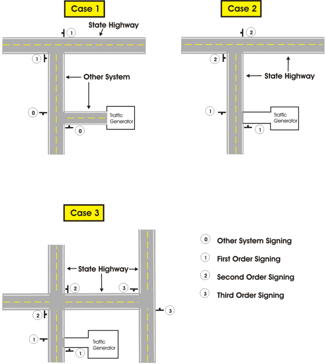
Support. In general, as the “order” of signing increases, the functional classification of road stays the same or increases. For example, if first order signing is on a four-lane U.S. route, second order signing should be on another U.S. route, expressway or a freeway. In this example case, second order signing should not be placed on a two-lane Route “ZZ.”
903.1.12 Sign Design (MUTCD Section 2A.06)
Support. This article shows many typical standard signs approved for use on streets, highways, bikeways and pedestrian crossings.
In the specifications for individual signs, the general appearance of the legend, color and size are shown in the accompanying tables and illustrations, and are not always detailed in the text.
Detailed drawings of standard signs and alphabets are shown in MoDOT Standard Plans and the federal Standard Highway Signs.
Figure 903.1.12: (D-29) (D-30)
A highway sign must be legible to those for whom it is intended and be understandable from a distance to permit a proper response. It is desirable for it to be highly visible by day and night and highly legible (i.e., adequately sized letters or symbols and a short legend for quick comprehension by an approaching traveler). Standardized colors and shapes are specified so that the several classes of traffic signs can be promptly recognized. Simplicity and uniformity in design, position, and application are important.
Standard. The term legend shall include all word messages and symbol designs that are intended to convey specific meanings. Uniformity in design includes shape, color, dimensions, legends, borders and illumination or retro-reflectivity.
Where a standard word message is applicable, the wording shall be as herein provided. Standardization of these designs does not preclude further improvement by minor changes in the proportion or orientation of symbols, width of borders, or layout of word messages, but all shapes and colors shall be as indicated.
In situations where word messages are required other than those herein provided, the signs shall be of the same shape and color as standard signs of the same functional type.
Guidance. Unless otherwise stated in this article for a specific sign or as stated in the Option below, phone numbers with more than four characters should not be shown on any sign, supplemental plaque, sign panel (including LOGO panels on specific service signs) or changeable message sign.
Option. Internet addresses or phone numbers with more than four characters may be shown on signs, supplemental plaques, sign panels, and changeable message signs that are intended for viewing only by pedestrians, bicyclists, occupants of parked vehicles, or drivers of vehicles on low-speed roadways where engineering judgment indicates that drivers can reasonably safely stop out of the traffic flow to read the message. Otherwise, internet addresses are not shown on any sign, supplemental plaque, sign panel (including LOGO panels on specific service signs) or changeable message sign. MoDOT may develop special word message signs in situations where roadway conditions make it necessary to provide road users with additional regulatory, warning, or guidance information.
903.1.13 Types of Fabricated Signs (MUTCD Section 2A.06a)
Support. There are two types of sign material available, structural (ST) and sheet (SH).
Sheet signs are sheet aluminum, usually one-piece units, and have several available thicknesses as indicated in the standard plans.
Structural signs are usually made of multiple 1-foot tall extruded panels, custom sized to the necessary width. These signs are used primarily for guide signs on expressways and freeways, but may be found on other routes on a limited basis, and are used on all overhead-mounted signs, including “LOW CLEARANCE” and exit number panels, signs greater than 6 ft. in width, and signs greater than 30 sq. ft. in area.
Extruded panel signs are structural signs composed of an aluminum substrate, made up of 1 ft. tall “E” shaped aluminum panels, assembled to a desired height and cut to a uniform width for each sign. These panels are bolted together to form the larger “blank” substrate needed for a large sign.
Extruded sheet signs are structural signs composed of aluminum sheets welded to extruded aluminum-strengthening bars. The bars are oriented horizontally. This type of sign is typically found on large LOGO signing.
Overlay of existing extruded panel is a thin aluminum substrate applied over an existing sign face. The overlay duplicates all legend and characters on the original sign face. This is a cost-effective method to refurbish structural signs. An extruded panel sign should be only overlaid once.
Welded-stud panel signs are structural signs composed of aluminum sheets with aluminum bolt studs welded to the back of the sheets. These studs serve as fasteners to which splice plates and mounting brackets are secured. Welded-stud panel signs are no longer fabricated.
Option. As an alternative to structural sign replacement, a sign overlay may be ordered. Any extruded panel sign may receive an overlay.
Standard. Any demountable legend should be removed prior to the installation of the new overlay panels.
Extruded sheet signs and welded-stud panel signs shall not be overlaid.
Welded-stud panel signs shall be replaced with extruded panel signs at the end of the useful life of their sheeting and/or legend.
903.1.14 Changeable/Dynamic Message Signs (CMS/DMS) (MUTCD Section 2A.07)
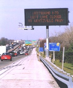
Standard. As far as is practical, changeable message signs, traffic control devices designed to display variable messages, shall conform to the principles established in this article and with the design and applications prescribed in 903.8.27, Changeable Message Signs for freeway and expressway guide signs and the Traffic Control for Field Operations.
Messages displayed shall convey pertinent information to assist motorists in their driving decisions. Messages shall be conveyed in a standard, non-confusing manner that allows drivers to both perceive and react to the information in a timely fashion.
The district engineer shall authorize the use of all CMS/DMS, both state and contractor furnished. Access to the CMS/DMS shall only be given to responsible individuals. The district engineer shall ensure that efforts are coordinated such that motorists are informed of the most critical information based on priority of messages listed below.
Messages shall be displayed on stationary DMS according to the priorities listed below. When a stationary DMS is not being used to display one of these message types, it shall either remain blank or display a simple character to indicate to motorists that the sign is operational but no action message is currently necessary.
A DMS shall not advertise or promote commercial events or entities and shall only display messages pertaining to highway safety or congestion reduction. A DMS shall not repeat guide sign, regulatory sign or warning sign messages.
Types of messages conveyed on stationary DMS have the following priority:
A. Emergencies such as evacuations or closures required by MoDOT, the Emergency Management Agency (SEMA), local law enforcement or the military.

B. Hazardous and/or uncommon road conditions, which require motorists to alter their driving, such as severe weather conditions, collisions, work zone activities or other incidents.
C. Traveler information and suggested alternate routes for delays and/or congestion caused by planned or unplanned incidents.
D. Advance notice for scheduled incidents such as lane closures, road closures, moving operations or special events.
Messages shall be displayed on portable CMS according to the priorities listed below. When a portable CMS is not being used to display one of these message types, the board shall be turned parallel to traffic or the CMS removed.
CMS shall not be used to convey the same message for an extended period of time that could be conveyed with a conventional guide sign, regulatory sign or warning sign.
Types of messages conveyed on portable CMS shall have the following priority:

A. Emergencies such as evacuations or closures required by MoDOT, the State Emergency Management Agency (SEMA), local law enforcement or the military.
B. Hazardous and/or uncommon road conditions, which require motorists to alter their driving, such as severe weather conditions, collisions, work zone activities or other incidents.
C. Short term detours (mandatory) for a partial audience for which no other signing is in place.
D. Traveler information and suggested alternate routes for delays and/or congestion caused by planned or unplanned incidents.
E. Advance notice for scheduled incidents such as lane closures, road closures, moving operations, or newly installed 4-way stops or signals.
A CMS shall not advertise or promote commercial events or entities. Only messages that pertain to highway safety or congestion reduction shall be displayed. If it is anticipated that a public or commercial event will generate a large volume of traffic or create congestion problems, a CMS may be used to facilitate traffic flow during the event but shall not advertise the event.
A portable CMS is normally used to warn motorists of specific emergencies, active work zones, hazardous road conditions and unexpected detours. A CMS used in situations such as these shall not be used to display child abduction alert messages.
A portable CMS used for a child abduction alert message shall be programmed and installed at an appropriate location in a timely manner (within one hour of the abduction notification), and follow the guidelines in Traffic Control for Field Operations.
Using a portable CMS to display a child abduction alert message shall follow the requirements and procedures outlined above for stationary DMS, except that the district engineer or designated person or persons shall be responsible for determining the availability, use and cancellation of the CMS for this purpose.
Guidance. If a child abduction occurs and it meets the local AMBER Plan Program’s criteria for triggering an alert, a child abduction alert (AMBER Alert) message should be displayed on all stationary DMS in the area of the abduction. If one of the above types of messages is currently being displayed on a stationary DMS, a child abduction alert message should be alternated with that message until the child abduction alert is cancelled.
MoDOT’s Traffic Management Center (TMC) Manager or similar district position should work with local law enforcement to determine an appropriate child abduction alert message that conveys necessary information but does not create an adverse traffic impact such as queues, unexpected slowing of traffic, etc.
The following display messages should be programmed and displayed for a child abduction alert:
- MISSING
- CHILD
- ALERT
- TUNE TO
- LOCAL
- MEDIA
Except for safety or transportation-related messages, changeable message signs should not be used to display information other than regulatory, warning, and guidance information related to traffic control.
Support. The following display message is an example of a generic AMBER Alert message that could be programmed.
- CHILD ABDUCTION ALERT
- TUNE TO LOCAL MEDIA
- FOR UPDATES
Changeable message signs with more sophisticated technologies are gaining widespread use to inform road users of variable situations, particularly along congested traffic corridors.
Information regarding the design and application of portable changeable message signs in temporary traffic control zones is contained in 616.3 Changeable Message Signs and MoDOT Traffic Control for Field Operations. Abbreviations Used on Traffic Control Devices, 903.19.14, contains information regarding the use of abbreviations on traffic control devices, including changeable message signs.
Option. Changeable message signs (including portable changeable message signs) that display a regulatory or warning message may use a black background with a white, yellow, orange, red, or fluorescent yellow-green legend as appropriate, except where specifically restricted for a particular sign.
Changeable message signs, both permanent and portable, may be used by MoDOT to display safety or transportation-related messages.
CMS and DMS may be used to effectively reduce congestion caused by planned events or unplanned incidents such as excessive daily traffic, accidents, detours, construction delays, etc. Once a driver population has gained confidence that messages are reliable and relay pertinent information that assists in reducing delays, CMS and DMS may be used to convey information to alter traffic patterns or modes of transportation.
The district engineer may designate a person, or persons, to be responsible for the authorization of use, messages to be displayed, and the care, maintenance and security of the CMS/DMS. This person, or persons, may delegate certain responsibilities in regard to the CMS/DMS, but shall ensure that any personnel given access to the CMS/DMS understands and adheres to both this policy and applicable MUTCD requirements.
Other public information that assists MoDOT in improving highway safety and reducing congestion may be displayed after careful consideration. The message shall, however, require motorists to alter their driving, and direct approval by the district engineer or authorized designee must be received prior to displaying the message.
If a portable CMS is not being used to improve traffic safety, it may be used to display a child abduction alert message.

Support. Examples of safety messages include SEAT BELTS BUCKLED? and DON’T DRINK AND DRIVE. Examples of transportation-related messages include STADIUM EVENT SUNDAY, EXPECT DELAYS NOON TO 4 PM and OZONE ALERT CODE RED—USE TRANSIT.
Guidance. When a CMS is used to display a safety or transportation-related message the message should be simple, brief, legible and clear. A CMS should not be used to display a safety or transportation-related message if doing so would adversely affect the respect for the sign. “CONGESTION AHEAD” or other overly simplistic or vague messages should not be displayed alone. These messages should be supplemented with a message on the location or distance to the congestion or incident, how much delay is expected, alternative route or other similar messages.
Standard. When a CMS is used to display a safety or transportation-related message, the display format shall not be of a type that could be considered similar to advertising displays. The display format shall not include animation, rapid flashing or other dynamic elements that are characteristic of sports scoreboards or advertising displays.
903.1.15 Retroreflectivity and Illumination (MUTCD Section 2A.08)

Support. There are many materials currently available for retroreflection and various methods currently available for the illumination of signs. New materials and methods continue to emerge. New materials and methods can be used as long as the signs meet the standard requirements for color, both by day and by night.
There are two types of reflective sheeting available to MoDOT: high intensity (R2) and microprismatic (R3). For special sign designs, the type of reflective sheeting is noted on the special sign detail sheet (indicated as “BACKGROUND”).
Standard. Regulatory, warning, and guide signs shall be retroreflective or illuminated to show the same shape and similar color by both day and night, unless specifically stated otherwise in this article about a particular sign or group of signs.
The requirements for sign illumination shall not be considered to be satisfied by street or highway lighting.
| LED Signal |
| Report 2000 |
| See also: Innovation Library |
Guidance. R2 sheeting should be used on all sign backgrounds. R3 sheeting should be used on all legend and symbols on guide signs.
Overhead sign installations should not be illuminated unless an engineering study shows a need for illumination, i.e. fog prone areas.
Option. Light-emitting diode (LED) units may be used individually within the face of a standard highway sign and in the border of a standard highway sign, except for Changeable Message Signs, to improve the conspicuity, increase the legibility of sign legends and borders or provide a changeable message. Individual LED pixels may be used in the border of a sign.
Standard. If used, the LEDs shall be the same color as the standard highway sign legend, border, or background. If flashed, all LED units shall flash simultaneously at a rate of more than 50 and less than 60 times per minute. The uniformity of the sign design shall be maintained without any decrease in visibility, legibility or driver comprehension during either daytime or nighttime conditions.
A module of multiple LED units used as a closely spaced, single light source shall only be used within the sign face for legends or symbols.
Support. Information regarding the use of retroreflective material on the sign support is contained in Posts and Mounting.
903.1.16 Minimum Retroreflectivity Levels (MUTCD Section 2A.09)
Reserved for future text depending on FHWA rulemaking.
903.1.17 Shapes (MUTCD Section 2A.10)
Standard. Specific shapes, as shown below, shall be exclusively used for specific signs or series of signs unless stated otherwise about a particular sign or class of signs.
Table 903.1.17 Use of Sign Shapes
| Shape | Signs |
|---|---|
| Octagon | * Stop |
| Equilateral Triangle (1 point down) | * Yield |
| Circle | * Highway-Rail Grade Crossing (Advance Warning) |
| Pennant Shape/Isosceles Triangle (longer axis horizontal) | * No Passing |
| Pentagon (Pointed up) | * School Advance Warning sign |
| Crossbuck (two rectangles in an "x" configuration) | * Highway-Rail Grade Crossing |
| Diamond | Warning Signs |
| Rectangle (including square) | Regulatory Series **Guide Series
Warning Series |
| * This sign shall be exclusively the shape shown. | |
| **Guide series includes general service, specific service, recreation and emergency management signs | |
903.1.18 Sign Colors (MUTCD Section 2A.11)

Standard. The colors to be used on standard signs and their specific use on these signs shall be as indicated in this article. The color coordinates and values shall be as described in Tables 903.1.18.1 and 903.1.18.2, MoDOT Sign Detail Manual and in 23 CFR, Part 655, Subpart F, Appendix.
Support. As a quick reference, common uses of sign colors are shown in Tables 903.1.18.1 and 903.1.18.2. Color schemes on specific signs are shown in the illustrations located in each appropriate section.
Whenever white is specified herein as a color, it is understood to include silver-colored retroreflective coatings or elements that reflect white light. The colors coral, purple and light blue are being reserved for uses that will be determined in the future by the FHWA. Information regarding color coding of destinations on guide signs is contained in 903.7, Color, Retroreflection and Illumination.
Table 903.1.18.1 Common Uses of Sign Legend Colors
| Type of Sign | Legend | ||||
|---|---|---|---|---|---|
| Black | Green | Red | White | Yellow | |
| Regulatory | X | - | X | X | - |
| Prohibitive | - | - | X | X | - |
| Permissive | - | X | - | - | - |
| Warning | X | - | - | - | - |
| Pedestrian | X | - | - | - | - |
| Bicycle | X | - | - | - | - |
| Guide | - | - | - | X | - |
| Interstate Route | - | - | - | X | - |
| State Route | X | - | - | - | - |
| US Route | X | - | - | - | - |
| County Route | - | - | - | - | X |
| Forest Route | - | - | - | X | - |
| Street Name | - | - | - | X | - |
| Destination | - | - | - | X | - |
| Reference Location | - | - | - | X | - |
| Information | - | - | - | X | - |
| Evacuation Route | - | - | - | X | - |
| Road User Service | - | - | - | X | - |
| Recreational | - | - | - | X | - |
| Temporary Traffic Control | X | - | - | - | - |
| Incident Management | X | - | - | - | - |
| Changeable Message Signs* | - | - | - | X | X |
| School | X | - | - | - | - |
| * Reverse colors or fluorescent yellow-green pixels may also be used on changeable message signs. | |||||
Table 903.1.18.2 Common Uses of Sign Background Colors
| Type of Sign | Background | |||||||||
|---|---|---|---|---|---|---|---|---|---|---|
| Black | Blue | Brown | Green | Orange | Red | White | Flourescent Yellow | Flourescent Yellow-Green | Flourescent Pink | |
| Regulatory | X | - | - | - | - | X | X | - | - | - |
| Prohibitive | - | - | - | - | - | X | X | - | - | - |
| Permissive | - | - | - | - | - | - | X | - | - | - |
| Warning | - | - | - | - | - | - | - | X | - | - |
| Pedestrian | - | - | - | - | - | - | - | X | X | - |
| Bicycle | - | - | - | - | - | - | - | X | X | - |
| Guide | - | - | - | X | - | - | - | - | - | - |
| Interstate Route | - | X | - | - | - | X | - | - | - | - |
| State Route | - | - | - | - | - | - | X | - | - | - |
| US Route | - | - | - | - | - | - | X | - | - | - |
| County Route | - | X | - | - | - | - | - | - | - | - |
| Forest Route | - | - | X | - | - | - | - | - | - | - |
| Street Name | - | - | - | X | - | - | - | - | - | - |
| Destination | - | - | - | X | - | - | - | - | - | - |
| Reference Location | - | - | - | X | - | - | - | - | - | - |
| Information | - | X | - | X | - | - | - | - | - | - |
| Evacuation Route | - | X | - | - | - | - | - | - | - | - |
| Road User Service | - | X | - | - | - | - | - | - | - | - |
| Recreational | - | - | X | X | - | - | - | - | - | - |
| Temporary Traffic Control | - | - | - | - | X | - | - | - | - | - |
| Incident Management | - | - | - | - | X | - | - | - | - | X |
| Changeable Message Signs* | X | - | - | - | - | - | - | - | - | - |
| School | - | - | - | - | - | - | - | X | X | - |
| * Reverse colors or fluorescent yellow-green pixels may also be used on changeable message signs. | ||||||||||
903.1.19 Dimensions (MUTCD Section 2A.12)
Support. Sign sizes for use on the different classes of highways are shown in 903.5.3, 903.6.4, 903.7.4, 903.16.5 and 903.17.6.1, the MoDOT Traffic Control for Field Operations and in Standard Highway Signs.
Standard Highway Signs prescribes design details for up to five different sizes depending on the type of traffic facility, including bikeways. Smaller sizes are designed to be used on bikeways and some other off-road applications. Larger sizes are designed for use on freeways and expressways and can also be used to enhance road user safety and convenience on other facilities, especially on multi-lane divided highways and on undivided highways having five or more lanes of traffic and/or high speeds. The intermediate sizes are designed to be used on other highway types.
Standard. The sign dimensions prescribed in this article, the Sign Detail Manual, and the federal Standard Highway Signs shall be used unless engineering judgment determines that other sizes are appropriate. Where engineering judgment determines that sizes smaller than the prescribed dimensions are appropriate for use, the sign dimensions shall not be less than the minimum dimensions specified in this article. Where engineering judgment determines that sizes larger than the prescribed dimensions are appropriate for use, standard shapes and colors shall be used and standard proportions shall be retained as much as practical.
Guidance. Increases above the prescribed sizes should be used where greater legibility or emphasis is needed. Wherever practical, the overall sign dimensions should be increased in 12-in. increments.
903.1.20 Symbols (MUTCD Section 2A.13)
Support. Sometimes a change from word messages to symbols requires significant time for public education and transition. Therefore, this article includes the practice of using educational plaques to accompany some new symbol signs.
Standard. Symbol designs shall in all cases be unmistakably similar to those shown in this article, the Sign Detail Manual and the federal Standard Highway Signs. New symbol designs shall be adopted by the Federal Highway Administration based on research evaluations to determine road user comprehension, sign conspicuity, and sign legibility.
Guidance. An educational plaque should accompany new warning or regulatory symbol signs not readily recognizable by the public.
Option. State and/or local highway agencies may conduct research studies to determine road user comprehension, sign conspicuity, and sign legibility.
Educational plaques may be left in place as long as they are in serviceable condition.
Although most standard symbols are oriented facing left, mirror images of these symbols may be used where the reverse orientation might better convey to road users a direction of movement.
903.1.21 Word Messages (MUTCD Section 2A.14)
Standard. Except as noted in Types of Fabricated Signs, all word messages shall use standard wording and letters as shown in this article, the Sign Detail Manual, and the federal Standard Highway Signs.
Guidance. Word messages should be as brief as possible and the lettering is to be large enough to provide the necessary legibility distance. A minimum specific ratio, such as 1 inch of letter height per 40 ft. of legibility distance, should be used.
Support. Some research indicates that a ratio of 1 in. of letter height per 33 ft. of legibility distance could be beneficial.
Guidance. Abbreviations (refer to 903.19.14) should be kept to a minimum and should include only those that are commonly recognized and understood such as AVE (for Avenue), BLVD (for Boulevard) and JCT (for Junction).
Standard. All sign lettering shall be in capital letters as established in Sign Design and the federal Standard Highway Signs except as indicated in the Option below.
Option. Word messages on street name signs and destinations on guide signs may be composed of a combination of lower case letters with initial upper case letters.
903.1.22 Sign Borders (MUTCD Section 2A.15)
Refer to Sign Detail for border information.
903.1.23 Location Standardization (MUTCD Section 2A.16)
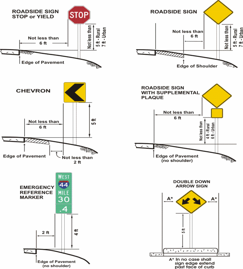
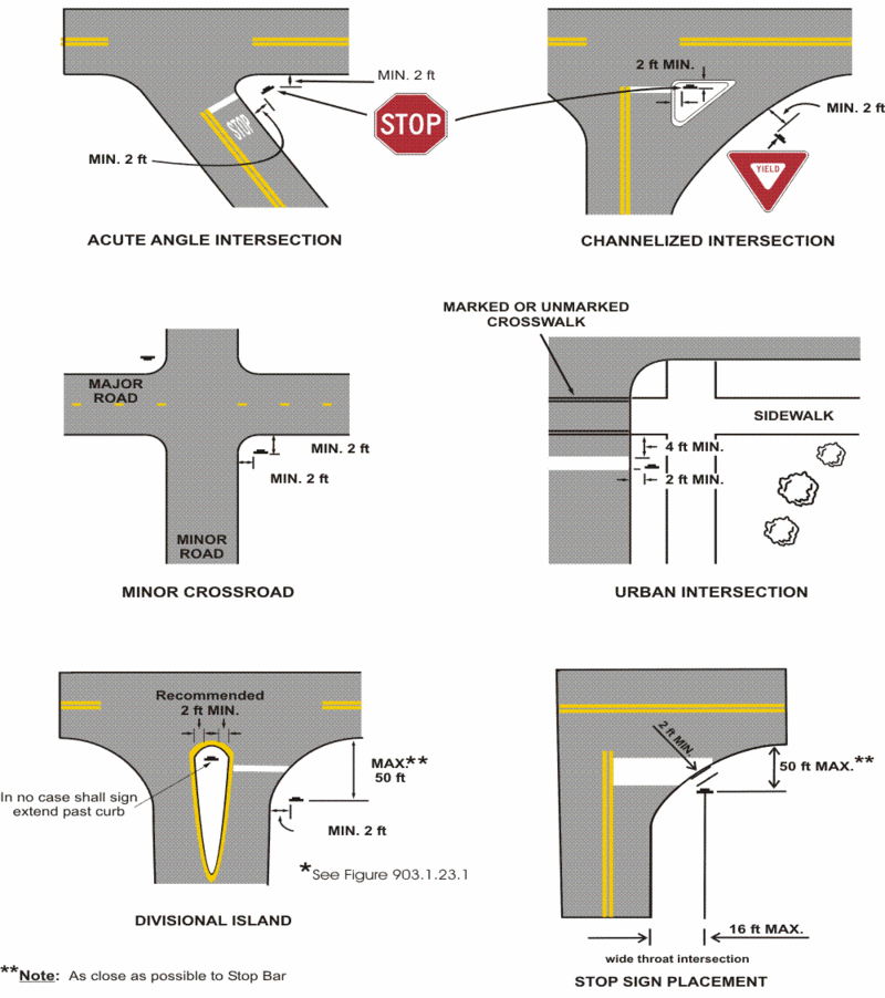
Support. Standardization of position cannot always be attained in practice. Examples of heights and lateral locations of signs for typical installations are illustrated in Figure 903.1.23.1 and examples of locations for typical signs at intersections are illustrated in Figures 903.1.23.2 and 903.1.23.3.
Standard. Signs requiring multiple decisions by the traveler shall be spaced sufficiently far apart for the required decisions to be made reasonably safely. One of the factors considered when determining the appropriate spacing shall be the posted or 85th-percentile speed.
Guidance. Signs should be located on the right side of the roadway where they are easily recognized and understood by travelers. Signs in other locations should be considered only as supplementary to signs in the normal locations, except as otherwise indicated.
Signs should be individually installed on separate posts or mountings except where:
A. One sign supplements another, or
B. Route or directional signs are grouped to clarify information to motorists, or
C. Regulatory signs that do not conflict with each other are grouped, such as turn prohibition signs posted with one-way signs, street name signs posted with a stop or yield sign, or a parking regulation sign posted with a speed limit sign.
Signs should be located so that they:
A. Are outside the clear zone unless placed on a breakaway or yielding support (see Lateral Offset);
B. Optimize nighttime visibility;
C. Minimize the effects of mud splatter and debris;
D. Do not obscure each other;
E. Are not hidden from view; and
F. Do not block view of intersection.
Support. The clear zone is the roadside border area measured from the edge of the pavement that is available for the safe use by errant vehicles as determined according to Chapter 3 of the AASHTO Roadside Design Guide. The width of the clear zone depends on traffic volumes, speeds and roadside geometry.
Guidance. Because of increased traffic, an order of sign installation priority should be established to provide travelers with regulatory, warning, and guidance information.
Support. An order of priority is especially critical where space is limited for sign installation and there is a demand for several different types of signs. Overloading motorists with too much information is not desirable.
Guidance. Because regulatory and warning information is more critical to travelers than guidance information, regulatory and warning signing whose location is critical should be displayed rather than guide signing in cases where conflicts occur. Information of a lesser critical nature should be moved to less critical locations or omitted.
Option. Signs may be placed on median islands or on the left side of the road under some circumstances, such as on curves to the right. A supplementary sign located on the left of the roadway may be used on a multi-lane road where traffic in the right lane might obstruct the view to the right.
Guidance. In urban areas where crosswalks exist, signs should not be placed within 4 ft. in advance of the crosswalk.
