Category:720 Mechanically Stabilized Earth Wall Systems: Difference between revisions
m Per CM, removed archaic SiteManager info and replaced with AASHTOWARE info |
updated per RR3823 |
||
| Line 34: | Line 34: | ||
====720.1.3.3 Miscellaneous Components==== | ====720.1.3.3 Miscellaneous Components==== | ||
Various material codes exist for reporting the components used in MSE walls. Most of these components are accepted by certification as outlined in [http://www.modot.org/business/standards_and_specs/SpecbookEPG.pdf#page=14 Sec 1052]. Consult the Sampling Checklist regarding reporting requirements for your specific project. | Various material codes exist for reporting the components used in MSE walls. Most of these components are accepted by certification as outlined in [http://www.modot.org/business/standards_and_specs/SpecbookEPG.pdf#page=14 Sec 1052]. Consult the Sampling Checklist regarding reporting requirements for your specific project. | ||
==720.2 Design Requirements== | |||
===720.2.1 MSE Wall Systems (Permanent MSE Wall Systems and Temporary MSE Wall Systems) Specified on Plan Details=== | |||
The contractor shall be responsible for the internal and external stability of the structure including compound stability. Typically, the wall manufacturer/designer will provide these requirements for the contractor. For permanent MSE walls the owner (the Geotechnical Engineer of record or their agent) is responsible for the in-situ soil design parameters on plan details, foundation bearing capacity/resistance, settlement, and overall global stability. The contractor is responsible for verifying that the applied bearing stress is less than the provided bearing capacity/resistance. For staged bridge construction, see [[751.1_Preliminary_Design#751.1.2.11_Staged_Construction|EPG 751.1.2.11 Staged Construction]]. | |||
For temporary MSE walls the contractor will use the in-situ soil design parameters provided by the owner for the permanent MSE wall, but the contractor is responsible for global stability. Typically, the tallest portion of a temporary MSE wall is constructed at the same foundation elevation as the permanent wall except case 2, option 1 where the temporary wall is required to retain the improved foundation. Temporary MSE wall for staged bridge construction might have much higher height than permanent MSE wall height. It is important to ensure that global stability has been performed by the contractor for the temporary wall. For additional information, see [[751.24_LFD_Retaining_Walls#751.24.2_Mechanically_Stabilized_Earth_.28MSE.29_Walls|EPG 751.24.2 Mechanically Stabilized Earth (MSE) Walls]]. Typical examples for temporary MSE walls are given below. | |||
:Case 1: Temporary MSE wall (unimproved foundation ground) | |||
::Tallest section of temporary MSE wall height for a staged bridge construction is from top of temporary MSE wall (top of RDWY/approach slab or where the ground surface intercepts the temporary MSE wall facing) to bottom of temporary MSE wall (top of leveling pad of permanent MSE wall). By comparison, permanent MSE wall height is from top of coping to top of leveling pad. | |||
{| | |||
|- style="vertical-align:bottom;" | |||
| style="width: 40px" | | |||
| [[File:720.2.1_case1_elev.png|left|frame|<b><center>Elevation – Temporary MSE Wall (Unimproved Foundation Ground)</center></b>]] | |||
| [[File:720.2.1_case1_plan.png|left|frame|<b><center>Plan – Temporary MSE Wall (Unimproved Foundation Ground)</center></b>]] | |||
|- | |||
|} | |||
:Case 2: Temporary MSE wall (Improved foundation ground required per Geotech report for permanent MSE wall) | |||
::Option 1: Without temporary shoring (Temporary MSE wall to retain improved foundation material) | |||
:::Temporary MSE wall design height = Temporary MSE wall height in case 1 + leveling pad thickness + height of improved foundation ground. | |||
{| | |||
|- style="vertical-align:bottom;" | |||
| style="width: 60px" | | |||
| [[file:720.2.1_case2_option1_elev.png|left|frame|<b><center>Elevation – Temporary MSE Wall (Improved Foundation Ground: Option 1)</center></b>]] | |||
|- | |||
|} | |||
:::Note: For plan view, see option 2 minus temporary shoring. | |||
::Option 2: Temporary MSE wall with temporary shoring to retain improved foundation material | |||
:::Contractor shall install temporary shoring prior to installing improved foundation ground for stage 1. Contractor shall trim temporary shoring at top of leveling pad of precast MSE wall prior to excavate for next stage. Temporary shoring will retain improved foundation ground material. Temporary MSE wall design height is same as case 1. | |||
{| | |||
|- style="vertical-align:bottom;" | |||
| style="width: 60px" | | |||
| [[File:720.2.1_case2_option2_plan.png|left|frame|<b><center>Plan – Temporary MSE Wall (Improved Foundation Ground: Option 2)</center></b>]] | |||
| [[File:720.2.1_case2_option2_elev.png|700px|left|thumb|<b><center>Elevation – Temporary MSE Wall with Temporary Shoring (Improved Foundation Ground): Option 2</center></b>]] | |||
|- | |||
|} | |||
::Option 3: Without temporary shoring (No need to retain improved foundation material by temporary MSE wall) | |||
Geotech shall approve this option and suggest required minimum extension of improved foundation material into next staging area. Generally, 3 feet to 5 feet space needed to extend improved foundation from face of the temporary wall in the next staging area. For next stage construction, contractor shall excavate small area at a time and replace with improved foundation material to minimize shifting of improved foundation material from previous staging since there is no temporary shoring to retain improved foundation material. Contractor may need to provide temporary shoring to support existing structure to construct this option in tight space. Temporary MSE wall design height = Temporary MSE wall height in case 1. | |||
===720.2.2 Temporary shoring=== | |||
When temporary shoring is required by the contract documents, the contractor shall provide temporary shoring as needed in accordance with [https://www.modot.org/missouri-standard-specifications-highway-construction Sec 206]. If contractor plans to use a temporary MSE wall system, typically wire basket facing, as their method of providing temporary shoring then contractor shall be responsible for the internal stability, external stability, compound stability and global stability of the structure. Contractor shall use design parameters and foundation bearing capacity/resistance from permanent MSE wall plan details for design of temporary MSE wall system. A distinction should be made between the requirements for permanent MSE walls and temporary MSE walls. For permanent walls the manufacturer/designer typically only provides internal, external and compound stability and the engineer is responsible for global stability. The contractor shall submit the proposed method of temporary shoring construction to the engineer prior to beginning work. For additional information, see [[751.24_LFD_Retaining_Walls#751.24.2_Mechanically_Stabilized_Earth_.28MSE.29_Walls|EPG 751.24.2 Mechanically Stabilized Earth (MSE) Walls]]. | |||
Revision as of 12:11, 9 February 2024
| Approved Products |
| Bridge Prequalified Products List |
720.1 Materials Guidance for Sec 720
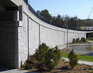
This guidance establishes procedures for inspection and reporting of small and large block mechanically stabilized earth (MSE) wall systems. Inspection of these items covers aggregate, geotextiles, blocks, face panels, reinforcing grids, and other miscellaneous hardware necessary as show on the wall system drawings.
720.1.1 Apparatus
None
720.1.2 Procedure
Sec 720 requires the contractor to deliver six copies of the MSE wall design plans. At least one of these copies should be forwarded to District Materials personnel.
The design of MSE wall systems must be approved by Bridge Division prior to construction. A listing of approved designs is maintained. If the design has not already been approved by Bridge Division, it must be submitted to Bridge and gain approval before construction can begin.
720.1.2.1 Contract Sampling and Testing Requirements
Once District Materials has received a copy of the MSE wall plans, they should edit the Contract Sampling and Testing Requirements accordingly. Since MSE wall designs vary greatly, care should be given as to what components and quantities are required. At a minimum, there should exist a requirement for reporting the entire approved wall system. Also, since the granular backfill plays a crucial role in supporting the structure, there should be a requirement for the acceptance of this material.
720.1.2.2 Certifications
Certifications should be received and checked for conformance to the various portions of Secs 720, 1052, 1011 and others necessary. The project office shall keep these certifications as part of the project files.
720.1.3 Reports
Due to the variance of designs, several AASHTOWARE Project (AWP) records may be required to correctly report acceptance of a MSE wall system and its components.
720.1.3.1 Completed Wall System
The acceptance of constructed wall system sections built to the approved design should be reported by Construction personnel using the 0720MSEW material code.
720.1.3.2 Granular Backfill
The certification for this material should be reviewed and a sample record made for acceptance. Any testing done to verify the certification will be reported using AWP.
720.1.3.3 Miscellaneous Components
Various material codes exist for reporting the components used in MSE walls. Most of these components are accepted by certification as outlined in Sec 1052. Consult the Sampling Checklist regarding reporting requirements for your specific project.
720.2 Design Requirements
720.2.1 MSE Wall Systems (Permanent MSE Wall Systems and Temporary MSE Wall Systems) Specified on Plan Details
The contractor shall be responsible for the internal and external stability of the structure including compound stability. Typically, the wall manufacturer/designer will provide these requirements for the contractor. For permanent MSE walls the owner (the Geotechnical Engineer of record or their agent) is responsible for the in-situ soil design parameters on plan details, foundation bearing capacity/resistance, settlement, and overall global stability. The contractor is responsible for verifying that the applied bearing stress is less than the provided bearing capacity/resistance. For staged bridge construction, see EPG 751.1.2.11 Staged Construction.
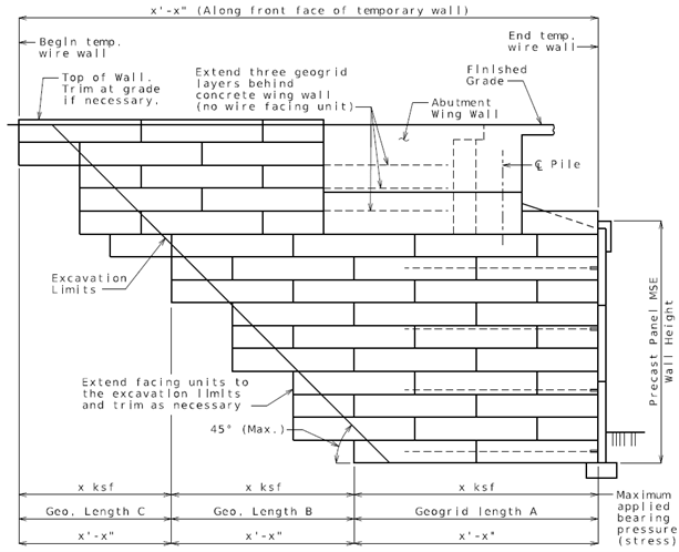
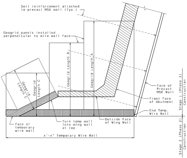
For temporary MSE walls the contractor will use the in-situ soil design parameters provided by the owner for the permanent MSE wall, but the contractor is responsible for global stability. Typically, the tallest portion of a temporary MSE wall is constructed at the same foundation elevation as the permanent wall except case 2, option 1 where the temporary wall is required to retain the improved foundation. Temporary MSE wall for staged bridge construction might have much higher height than permanent MSE wall height. It is important to ensure that global stability has been performed by the contractor for the temporary wall. For additional information, see EPG 751.24.2 Mechanically Stabilized Earth (MSE) Walls. Typical examples for temporary MSE walls are given below.
- Case 1: Temporary MSE wall (unimproved foundation ground)
- Tallest section of temporary MSE wall height for a staged bridge construction is from top of temporary MSE wall (top of RDWY/approach slab or where the ground surface intercepts the temporary MSE wall facing) to bottom of temporary MSE wall (top of leveling pad of permanent MSE wall). By comparison, permanent MSE wall height is from top of coping to top of leveling pad.
 |
 |
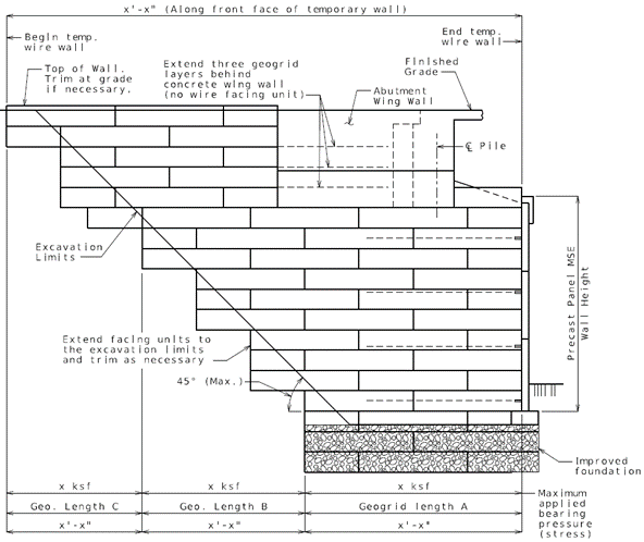
- Case 2: Temporary MSE wall (Improved foundation ground required per Geotech report for permanent MSE wall)
- Option 1: Without temporary shoring (Temporary MSE wall to retain improved foundation material)
- Temporary MSE wall design height = Temporary MSE wall height in case 1 + leveling pad thickness + height of improved foundation ground.
- Option 1: Without temporary shoring (Temporary MSE wall to retain improved foundation material)
 |
- Note: For plan view, see option 2 minus temporary shoring.
- Option 2: Temporary MSE wall with temporary shoring to retain improved foundation material
- Contractor shall install temporary shoring prior to installing improved foundation ground for stage 1. Contractor shall trim temporary shoring at top of leveling pad of precast MSE wall prior to excavate for next stage. Temporary shoring will retain improved foundation ground material. Temporary MSE wall design height is same as case 1.
- Option 2: Temporary MSE wall with temporary shoring to retain improved foundation material
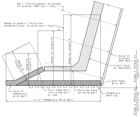 |
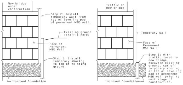 |
- Option 3: Without temporary shoring (No need to retain improved foundation material by temporary MSE wall)
Geotech shall approve this option and suggest required minimum extension of improved foundation material into next staging area. Generally, 3 feet to 5 feet space needed to extend improved foundation from face of the temporary wall in the next staging area. For next stage construction, contractor shall excavate small area at a time and replace with improved foundation material to minimize shifting of improved foundation material from previous staging since there is no temporary shoring to retain improved foundation material. Contractor may need to provide temporary shoring to support existing structure to construct this option in tight space. Temporary MSE wall design height = Temporary MSE wall height in case 1.
720.2.2 Temporary shoring
When temporary shoring is required by the contract documents, the contractor shall provide temporary shoring as needed in accordance with Sec 206. If contractor plans to use a temporary MSE wall system, typically wire basket facing, as their method of providing temporary shoring then contractor shall be responsible for the internal stability, external stability, compound stability and global stability of the structure. Contractor shall use design parameters and foundation bearing capacity/resistance from permanent MSE wall plan details for design of temporary MSE wall system. A distinction should be made between the requirements for permanent MSE walls and temporary MSE walls. For permanent walls the manufacturer/designer typically only provides internal, external and compound stability and the engineer is responsible for global stability. The contractor shall submit the proposed method of temporary shoring construction to the engineer prior to beginning work. For additional information, see EPG 751.24.2 Mechanically Stabilized Earth (MSE) Walls.