320.1 Preliminary Geotechnical Report (PGR): Difference between revisions
m Per CM, removed archaic SiteManager info and replaced with AASHTOWARE info |
m Per CM, provided updated Summary for Preliminary Geotechnical Report (Form M-41) and example of M-41 |
||
| Line 1: | Line 1: | ||
This guidance establishes procedures for sampling, laboratory testing and reporting for preliminary geotechnical investigations. | This guidance establishes procedures for sampling, laboratory testing and reporting for preliminary geotechnical investigations. | ||
{|style="padding: 0.3em; margin-left:15px; border:1px solid #a9a9a9; text-align:center; font-size: 95%; background:#f5f5f5" width=" | {|style="padding: 0.3em; margin-left:15px; border:1px solid #a9a9a9; text-align:center; font-size: 95%; background:#f5f5f5" width="260px" align="right" | ||
|-style="background:#f5f5f5" | |-style="background:#f5f5f5" | ||
|'''Figures''' | |'''Figures''' | ||
| Line 9: | Line 9: | ||
|[[media:320.1 Insoluble Residue Test lab report example.pdf|Insoluble Residue Test lab report example]] | |[[media:320.1 Insoluble Residue Test lab report example.pdf|Insoluble Residue Test lab report example]] | ||
|- | |- | ||
|[[#320.1.4.2 Summary for Preliminary Geotechnical Report - Form M-41|Summary for Preliminary Geotechnical Report | |[[media:320.1_M-41.docx|Summary for Preliminary Geotechnical Report (Form M-41)]] | ||
|- | |||
|[[#320.1.4.2 Example for the Summary for Preliminary Geotechnical Report - Form M-41|Example for Form M-41, Summary for Preliminary Geotechnical Report]] | |||
|- | |- | ||
|[[#320.1.4.3 Subsurface Logs for Preliminary Geotechnical Report - Form M-42|Subsurface Logs for Preliminary Geotechnical Report - Form M-42]] | |[[#320.1.4.3 Subsurface Logs for Preliminary Geotechnical Report - Form M-42|Subsurface Logs for Preliminary Geotechnical Report - Form M-42]] | ||
| Line 151: | Line 153: | ||
[[Image:320.1 Example Preliminary Geotechnical Report3.gif|center|700px|thumb]] | [[Image:320.1 Example Preliminary Geotechnical Report3.gif|center|700px|thumb]] | ||
===320.1.4.2 Summary for Preliminary Geotechnical Report - Form M-41=== | ===320.1.4.2 Example for the Summary for Preliminary Geotechnical Report - Form M-41=== | ||
[[image:320.1 | [[image:320.1.4.2_M-41_Example.jpg|center|700px|thumb]] | ||
===320.1.4.3 Subsurface Logs for Preliminary Geotechnical Report - Form M-42=== | ===320.1.4.3 Subsurface Logs for Preliminary Geotechnical Report - Form M-42=== | ||
Revision as of 12:38, 3 March 2022
This guidance establishes procedures for sampling, laboratory testing and reporting for preliminary geotechnical investigations.
320.1.1 Apparatus
A list of equipment requirements is contained in AASHTO R13 and ASTM D420-98.
320.1.2 Procedure
The preliminary geotechnical report originates in, and is the responsibility of, the District. Cut classification, preliminary sounding for structures, the locating of critical foundation areas, and fertility sampling are considered part of the preliminary geotechnical report. The preliminary geotechnical report shall be conducted essentially in accordance with AASHTO R13, “Conducting Geotechnical Subsurface Investigations”, and the Geology and Soils Manual, 1962 Edition, Chapter III, Missouri State Highway Commission. These references are guides and are not intended to preclude the use of ingenuity and judgment.
320.1.2.1 Description
Description of soils shall be in accordance with the visual-manual procedures of ASTM D2488. Description of rock materials shall be in accordance with ASTM C294. The Stratigraphic Succession in Missouri and subsequent publications of the Missouri DNR, Division of Geology and Land Survey shall be used as guides to stratigraphic identification. Rock quality designation (RQD) shall be used wherever applicable in logging rock cores.
320.1.2.2 Sampling
Samples shall be obtained in accordance with methods listed in AASHTO R13. In addition, the Giddings slotted-tube sampler has proven particularly suitable for many preliminary geotechnical report sampling applications.
320.1.2.2.1 Soil Classification Samples
Samples shall be obtained, for classification by ASTM D 2487 and AASHTO M145 (except that group index will be calculated by procedures of M 145-49) and for determination of natural moisture content, at intervals of 5 ft. (1.5 m) or less in at least one hole from each cut with a significant amount of soil. Except in extraordinary circumstances, samples should be obtained from multiple (3 or more) representative locations and from each cut where depth of soil is 10 ft. (3 m) or more. Borrow areas other than roadway cuts shall be similarly sampled in detail to define the range of properties of the material to be borrowed. Classification samples shall be packaged in plastic bags, tied, and double packaged in heavy Kraft paper bags. Bags shall be securely packaged in heavy cardboard boxes for shipment. Alternately, samples may be packaged and shipped in small canvas sacks with plastic liners. Moisture samples shall be sealed in airtight containers for moisture determination in the district Operations Laboratory.
- Note: It is intended that sufficient samples shall be obtained, without sampling bias, so that test results will be reasonably indicative of the dispersion of properties of the soils to be encountered in grading. The number of locations sampled should depend upon the size of the job but three is considered the minimum acceptable for a small job. The number of samples at each location in turn should depend upon stratification and upon the depth of material to be excavated and/or left in place as subgrade.
320.1.2.2.2 Stabilization Samples
Samples shall be submitted for evaluation of lime stabilization, if applicable, in accordance with AASHTO M216, “Lime for Soil Stabilization.”
320.1.2.2.3 Fertility Samples
Composite samples of material, from each soil that will comprise the finished surface layer of the right-of-way to be seeded, shall be sent to the Laboratory for fertility tests. The number of samples will depend upon the judgment of the geologist. Samples should weigh about 1 lb (0.5 kg) and be shipped in small canvas sacks with plastic liners. The following information shall accompany the sample:
- (a) Soil type - by horizon(s) if applicable.
- (b) Type of project: rural, urban, or the approximate percentage of each when a combination.
- (c) Project location and length.
- (d) Station limits and approximate percentage of total area represented by the sample.
- (e) Whether sampling for the project is complete.
320.1.2.3 Sample Identification
Sample Identification record shall be entered in AASHTOWARE Project (AWP) and shall accompany all samples shipped to the Laboratory.
320.1.2.4 Quarantine Areas
In quarantine areas, all sampling procedures shall be in accordance with Quarantine Regulations.
320.1.2.5 Critical Foundation Areas
Requests for investigation of any critical foundation areas located during the preliminary geotechnical report shall be made in accordance with Foundation Investigations.
320.1.3 Report
320.1.3.1 Preliminary Geotechnical Report
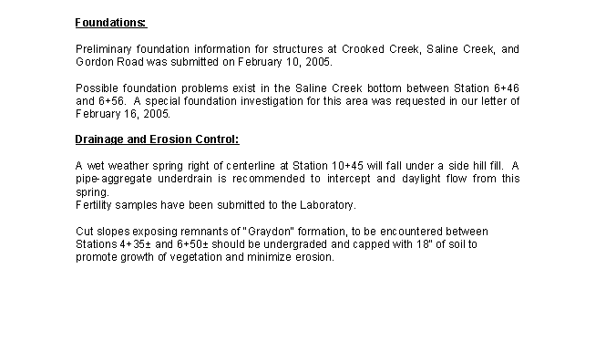
The report shall be in letter form as shown in the Example Preliminary Geotechnical Report. Since preliminary geotechnical reports differ in scope and complexity, a rigid format for the letter portion is not prescribed. This report should be clear, concise, and in outline form if long or detailed. The report shall contain the following information, as applicable:
- (a) Brief description of the project including location and station limits.
- (b) Identification and brief description of soil types and geologic formations to be encountered. Soil type descriptions shall include a note on the geologic origin, i.e., whether glacial, alluvial, residual, or loessial.
- (c) Recommendations on handling and classification of excavation, undergrading, and exceptions or additions to standard specifications for moisture control.
- (d) Definition, limits, and recommended disposition of unsuitable materials.
- (e) Contractor furnished borrow. If the contractor is to furnish borrow, specify those permissible soil types which will provide a suitable subgrade and which are both readily available and compatible with slope recommendations. Avoid specifying a soil type which may have only one practical source (and owner). Sample and report one or more possible borrow sites for each acceptable soil type where the owner expresses an interest in furnishing material. (This does not require a commitment on the part of the owner or the department and the contractor is free to use any other source provided defined criteria are met.)
- (f) Minimum slopes necessary for long term stability of cuts and fills including bridge spill slopes. The Guide for Slope Recommendations shall be used as a guide in preparing recommendations. Slopes should be no steeper than those shown in the Guide for Slope Recommendations and justification should be furnished for flatter or steeper slope recommendations. (Flattening or steepening of slopes for reasons unrelated to geotechnical considerations is not the responsibility of the geologist.) Placement of select, not necessarily granular, materials may be practical at bridge ends, particularly at grade crossings, to permit shortening of structures by steepening of spill slopes (in accordance with criteria of the Guide for Slope Recommendations). This is normally only practical with assured sources of select borrow which are readily distinguishable from less desirable materials.
- (g) Notation of the absence or presence of possible critical foundation areas and reference to special investigations in progress or completed by Geotechnical Engineering.
- (h) Recommendations for special drainage features or erosion control practices. Water table observations shall be made and reported for soil cuts whenever there is evidence that saturated conditions may exist. Recommendations shall be included in the report for drainage and/or stabilization of slopes and subgrade.
- In instances of widespread or non-localized seepage along areas of side hill fill, selective placement of blankets of available pervious material (normally rock from Class C excavation) should be considered to intercept and daylight the seepage to the outside toe of slope. Well-defined, localized seeps and spring flows, however, may be more economically handled with pipe-aggregate underdrains, particularly where project sources of rock or other pervious materials are limited or non-existent. See also paragraph (i) concerning placement of select granular materials for pavement drainage purposes.
- (i) All new pavement is to be constructed on two feet of select rock fill when that material is available in suitable quantities on the project site. This includes Light, Medium, and Heavy Duty pavements of either rigid or flexible design. The preliminary geotechnical report should include a statement concerning whether the quantity of select granular fill available on the job site is adequate, of appropriate quality, and located so that it could reasonably be placed as the top two feet (600 mm) of subgrade material. When the quantity of rock on a job is less than is necessary, but would be a significant portion of that needed, a general estimate of that proportion should also be given in the preliminary geotechnical report. Rock fill from sources other than the roadway balance should also be considered if within reasonable proximity to the job.
- Note: This information is important in the early stages of project development because the subgrade material to be used will effect the type of pavement selected, the thickness of a flexible pavement, the type of drainage required, and final elevations.
- (j) Location and recommended handling of sinkholes, caverns, mines, etc.
- (k) A condition survey of the existing pavement when applicable. (Note: A condition survey need not be considered or handled as a preliminary geotechnical report if done for routine resurfacing only. If a resurfacing project includes widening equivalent to at least one lane of pavement the condition survey should be handled as a preliminary geotechnical report including multiple subgrade samples.)
- (l) Any other information deemed necessary.
320.1.3.1.1 Summary for Preliminary Geotechnical Report
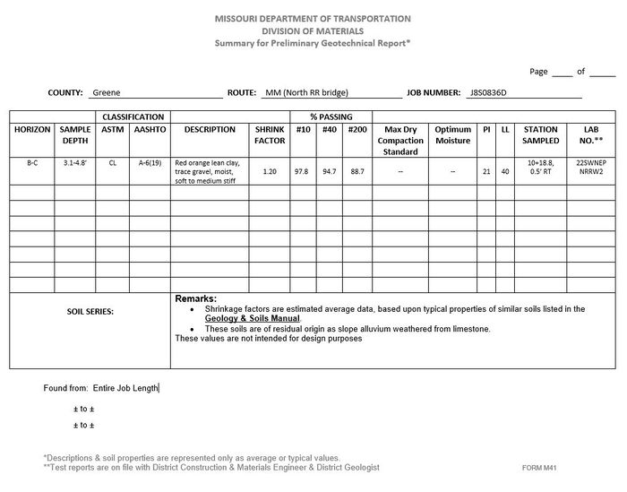
The Summary for Preliminary Geotechnical Report - Form M-41 is to be prepared and attached to the preliminary geotechnical report for each soil type (normally a pedologic series) encountered and is to contain general descriptions and typical or average test values for the various horizons. Discretion may be exercised as to which horizons justify inclusion of test data. Descriptive and interpretive comments, including the geologic origin of soils, shall be placed in the remarks section (recommendations are to be placed only in the text of the letter). Class A materials other than soils may also be summarized on the Summary for Preliminary Geotechnical Report - Form M-41. The soil shrinkage factor to be reported on this sheet is the ratio of maximum dry density, determined from the moisture-density relations test, to the natural dry density. This will be only one consideration for designers in estimating a balance shrinkage factor for the project.
Note: Form M-41 is not to be used as a substitute for Form M-42, Subsurface Logs for Preliminary Geotechnical Report. Form M-41 is a summary form and need only include that test data considered typical or average.
320.1.3.1.2 Subsurface Logs for Preliminary Geotechnical Report
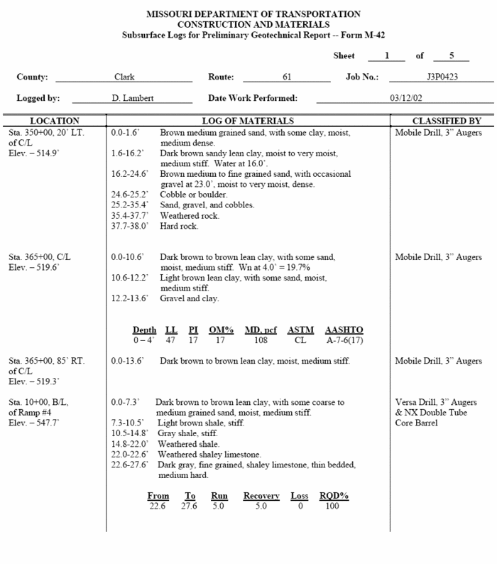
The Subsurface Logs for Preliminary Geotechnical Report - Form M-42 shall be used for all auger and core drill logs, etc., and shall be attached to the preliminary geotechnical report. All detailed sample test data shall be reported on this form in table form beneath the appropriate boring log.
(This will duplicate some data selected for use in the summary sheets. Core logs shall include, in table form, the driller's record of runs and recovery and, when appropriate, the rock quality designation (RQD) in percent.
Copies of the preliminary geotechnical report are to be distributed by the district as follows:
| Title | Copies |
|---|---|
| Geotechnical Director | Original & 2 |
| Project Manager | 1 |
| District Construction and Materials Engineer | 1 |
| File(s) |
Copies of the preliminary geotechnical report will be distributed by Geotechnical Engineering as follows:
| Title | Copies |
|---|---|
| State Design Engineer | 1 |
| State Bridge Engineer | 1 |
320.1.3.2 Preliminary Sounding for Structures
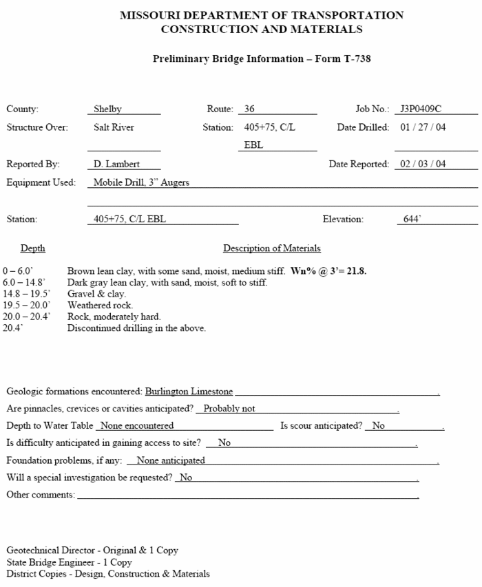
This report consists of a completed Preliminary Bridge Information - Form T-378. Logs of borings performed for the preliminary bridge report should also be reported in the preliminary geotechnical report on the Subsurface Logs for Preliminary Geotechnical Report - Form M-42 and are to be repeated on Preliminary Bridge Information - Form T-378 along with the other requested information on that form. Preliminary Bridge Information - Form T-378 has a different distribution than the preliminary geotechnical report and is to be reported separately. No cover letter is required. Copies of the completed form are to be distributed as follows:
| Title | Copies |
|---|---|
| Geotechnical Director | Original & 1 |
| State Bridge Engineer | 1 |
| File(s) |
320.1.3.3 Fertility Sample
No district report is required. Results of the fertility tests will be distributed by the Laboratory in accordance with Laboratory Testing.
320.1.4 Example Reports
320.1.4.1 Example Preliminary Geotechnical Report


320.1.4.2 Example for the Summary for Preliminary Geotechnical Report - Form M-41
320.1.4.3 Subsurface Logs for Preliminary Geotechnical Report - Form M-42
320.1.4.4 Preliminary Bridge Information - Form T-378
320.1.4.5 Guide for Slope Recommendations
Refer to Table 321.1 Guide for Selection of Slope Inclination for Routine Design.
320.1.5 Laboratory Testing
320.1.5.1 Procedure
Soils tests, upon request, are to be performed as shown in this Section. Test results and calculations for all tests except fertility are recorded on Form T-683R. Soil fertility test results and calculations are recorded in Laboratory workbooks. Fertility test results are also to be recorded on work form "Report of Test on Sample of Soil Fertility."
320.1.5.2 Routine Preliminary Geotechnical Report Tests
The following tests shall be performed on routine soil survey samples.
- (a) Liquid Limit - AASHTO T89, Mechanical Method (Alternate).
- (b) Plastic Limit and Plasticity Index - AASHTO T90.
- (c) Particle Size Analysis - AASHTO T88, except that hydrometer analysis is not required.
- (d) Soil Classification - AASHTO M145, except that the group index will be calculated by the procedures of M145-49.
- (e) Soil Classification - ASTM D2487, except that the data required for ASTM classification shall be determined by the AASHTO test methods of this section.
- (f) Moisture-Density Relations (Compaction Standard) - AASHTO T99, Method C.
320.1.5.3 Tests Specifically Requested
The following tests are considered non-routine and will be performed only on request.
- (a) Shrinkage Factors - AASHTO T92.
- (b) Specific Gravity - AASHTO T100.
- (c) Field Moisture Equivalent - AASHTO T93.
- (d) Moisture Content - ASTM D2216 (Normally this test should be performed in the District).
- (e) Fertility - A sample for fertility tests shall be initially prepared according to AASHTO T87. The test portion shall consist of approximately 100 g of material passing the No. 10 (2.00 mm) sieve. Fertility tests of soils shall be performed according to the methods set forth in "Soil Testing in Missouri", September 1973, by the Agronomy Department of the University of Missouri.
- (f) Rock Type Identification - Requests for rock type identification, for purposes of cut classification, are to be referred to the Geotechnical Section for determination of specific test requirements. Cores are the preferred form of sample since identification may be influenced by laminations or fissility and since cyclic lithologies could be misrepresented by composite samples. Tests to be performed, as applicable, may include microscopic examination and grain size count, mechanical analysis after degradation, insoluble residue determination and chemical analysis. The test report will indicate where samples may be subject to more than one interpretation of identification.
- (g) MoDOT Insoluble Residue (Procedure to Aid in Proper Cut Classification)
- The primary purpose of this system of identification is to provide a simple and quick method of cut classification which will be fair to both the state and the contractor. It is based on two accepted tests, the dividing points are justifiable according to authoritative geological authorities, and it is a little more than fair to the contractor.
- A representative sample is crushed and treated with hydrochloric acid. If more than 50% of the sample is remaining after treatment with the acid, the remaining sample or insoluble residue shall be used to determine the grain size.
- Interpretation
- 1. If 50% or more of the original weight is lost in solution by treatment with acid, the material will be classified as limestone or dolomite, both of which are Class C material.
- 2. If less than 50% dissolves, the material will be classed as sand or shale, pending the results of the sieve test.
- 3. If 50% or more of the insoluble material is larger than #270 sieve, it will be classed as sand.
- 4. If more than 50% of the insoluble residue is smaller than #270 sieve, the material will be classed as shale.
- The only thing remaining to be done then is to decide whether the sand is in ledge formation and whether or not it is cemented into sandstone.
- This proposed system is not to be construed as an attempt to set up a hard and fast method of classifying excavation materials. It does go a few steps beyond the specifications and reduces the personal equation to some extent. However, judgment will still be one of the primary factors in the final decision. It is possible, for example, when using this method of identification, to test one sample with 51% insoluble residue which contains more than 50% small sized material. It would be classed as shale – Class A, (#2 and #4, above). The next sample might have 49% insoluble material and be identified as Class C excavation (#1, above). For all practical purposes, there would be no difference in the difficulty of excavation.
- Although this would be an extreme case, it is a possibility and, if it should occur, certainly judgment would have to be the ruling factor. Similar cases might arise when excavating sandy shale. It must be remembered that no test is any better than the sample tested. Samples submitted for these tests should be taken with utmost care, and the greatest effort be directed toward obtaining material as nearly representative as possible of the disputed excavation materials. If it should be deemed necessary, in order to provide a satisfactory answer, numerous samples should be obtained. The amounts of money usually involved are so great that the cost of multiple tests would be negligible in comparison. Experience has shown that, if a dispute arises over proper classification of excavation materials, a 4 in. core can be examined and classified by the contractor’s representative and by the District Geologist, both of whom should be at the drill site at the same time. In order to avoid any possibility of either influencing the other, the examination should be made by each, separately, while the other occupies himself elsewhere. The respective logs should be compared after the examinations are completed, and the part or parts of the core on which there is disagreement can be removed from the complete core, identified, and sent to Jefferson City for laboratory tests. It is a good idea to have the sample identification sheets initialed by the contractor’s representative.
- Laboratory Procedure for Prepairing and Classifying Cut Classification Samples
- Apparatus:
- Hydrochloric Acid (HCl), specific gravity 1.19.
- 50% Hydrochloric Acid (HCl), by volume
- Borosilicate glass beakers, 2000 milliliter
- Balance sensitive to within 0.5 percent of the weight (mass) of sample to be weighed
- Aspiration system
- Glass stirring rod, at least 10 in. long
- Standard Sieve #10, #40, #100, #200, and #270
- Referenced Documents
- AASHTO Standards:
- T87-86 (2008) Dry Preparation of Disturbed Soil and Soil Aggregate Samples for Test M92 (2005) Wire-Cloth Sieves for Testing Purposes
- ASTM Standards:
- D1140 (2000) Standard Test Methods for Amount of Material in Soils Finer than the No. 200 (75 mm) Sieve
- Sample Preparation
- 1. The sample as received is split or reduced to yield a representative working sample weighing 3 to 4 lbs.
- 2. This sample is put through a small jaw type crusher to reduce the maximum particle size to passing #4 sieve.
- 3. The passing #4 sieve material is split on a sand splitter several times in order to obtain a representative sample weighing approximately 300 grams.
- 4. The 300 gram sample is then pulverized by means of a power driven rubble pestle, of special design in conjunction with a matching steel bowl or mortar, and/or by means of a burr mill until the total material will pass the #10 sieve. Care shall be exercised to assure that none of the material is degraded to less than individual grain size.
- 5. The 300 gram sample is then dried in an oven at 230°F. Two representative samples shall be obtained, each to consist of approximately 100 grams. One shall be accurately identified and saved, and the other used for testing.
- Insoluble Residue Test
- 6. Weigh approximately 100 grams of the appropriate sample in a 2000 milliliter beaker and record to the nearest 0.1 gram.
- 7. Slowly add 200 milliliters of 50% HCI solution (see note below). As the reaction subsides, add 25 milliliters of concentrated HCI as needed to increase the rate of reaction.
| Use extreme caution when adding acid. For classification samples high in carbonates,the reaction may be very vigorous during the initial stages of the reaction. If the sample is in danger of overflowing the beaker, add small amounts of DI water with a wash bottle until the reaction slows. |
- 8. When the addition of concentrated HCI no longer increases the rate of reaction, dilute sample to 1400 milliliters with DI water and stir. Stir after each addition of DI water, as this will assist in expelling any trapped acid in the residue.
- 9. Let sample settle to the bottom of the beaker for at least 3 hours.
- 10. After a minimum of 3 hours, carefully siphon liquid from the beaker to an approximate 250 ml mark on the beaker using an aspiration system. Pay close attention not to disturb the sample while performing this procedure. Repeat this at least 2 more times so that all acid has been removed from the sample. During last wash, remove stirring rod and transfer any material adhering to the rod with bottle of DI water.
- 11. Place beaker in 105 degrees C oven overnight.
- 12. Take beaker out of oven, cool, and weigh beaker to constant weight. Record the mass of the beaker with residue.
- 13. Calculate the percentage acid insoluble residue as follows:
- Percentage acid insoluble residue = 100 x (weight of insoluble residue / original weight of sample)
- If the weight is less than 50 percent of the original weight, the sample is classified as a limestone and further testing is not required.
- Sieve Test
- 14. If more than 50 percent of the original weight remains undissolved at the completion of the addition of HCL, the insoluble residue shall be used to determine the grain size. The sample is placed in a beaker, mixed with a solution of calgon and permitted to stand for 18 hours. This mixture is dispersed with a stirring device and washed over a #270 sieve. The retained portion is dried and a gradation run using the following sieves: #10, #40, #100, #200, and #270.
- 15. If more than 50% of the insoluble residue passes the #270 sieve, the sample is to be classified as a shale. If less than 50% passes the #270 sieve, the sample is to be classified as a sand.
320.1.5.4 Report
All test results, except fertility and rock type identification are reported through AWP, with distribution to:
- District Construction and Materials Engineer
Fertility test results are reported on the AWP Lab Report, with distribution as follows:
- State Maintenance Engineer
- District Construction and Materials Engineer
- File
Rock Type Identification test results will be reported on the appropriate forms to the Geotechnical Director with a file copy maintained by the Laboratory Director. The Geotechnical Section will determine the rock type identification to be submitted by letter to the District Engineer.
320.1.6 Geotechnical Laboratory Testing
This guidance establishes procedures for the soil tests routinely performed by the Geotechnical Section.
320.1.6.1 Apparatus
The required equipment is listed in the appropriate method as described in this section.
320.1.6.2 Procedure
320.1.6.2.1 Unconfined Compressive Strength
Unconfined compressive strength is to be determined in accordance with AASHTO T208.
320.1.6.2.2 Consolidation
Consolidation characteristics of soils are to be determined in accordance with AASHTO T216.
320.1.6.2.3 Triaxial Compression
Triaxial strength parameters are to be determined in accordance with AASHTO T234.
320.1.6.2.4 Direct Shear
The direct shear test is to be performed in accordance with AASHTO T236.
320.1.6.2.5 Swell Test
The swell of soil is determined in accordance with AASHTO T216 except as follows:
- (a) Select the restraining load. Restraining loads are to be based on the anticipated load on the soil in place in the subgrade.
- (b) Apply the load, record the zero reading and inundate the sample.
- (c) Record the increase in height of the sample daily until movement ceases.
- (d) Percent swell is the change in height of the sample divided by the original height of the sample.
320.1.6.2.6 Constant-Head Permeability
The permeability of granular soils containing not more than 10 percent non-plastic material passing the No. 200 [75 mm] sieve is to be determined in accordance with AASHTO T215.
320.1.6.2.7 Falling-Head Permeability
The permeability of granular cohesion less materials consisting predominantly of particles passing the No. 10 (2.00 mm) sieve may also be determined in accordance with "Suggested Method of Test for Permeability of Porous Granular Materials by the Falling-Head Permeameter", Special Procedures for Testing Soil and Rock for Engineering Purposes, ASTM STP 479, 1970, except that:
- (a) A steel permeameter with an inside diameter of 4 in. (100 mm) and a height of 4.6 in. (116.8 mm) shall be used.
- (b) Soil shall be compacted in the permeameter in accordance with AASHTO T99, Method C.
320.1.6.2.8 Permeability of Fine-Grained Soils
Permeability of fine-grained soils is generally to be computed from consolidation test data and may be determined by direct measurements on triaxial shear specimens.
320.1.6.2.9 California Bearing Ratio
The California Bearing Ratio (CBR) is to be determined according to AASHTO T193.
320.1.6.3 Report
All test results are to be reported to the Geotechnical Director. A summary of test data is normally to be included as an attachment to the reports of special investigations.