237.13 Contract Plan File Name Convention: Difference between revisions
m →237.13.2 Electronic Design Data: Per CADD, updated list of electronic design data files generated from GEOPAK for Roadway Contract Plans |
m →237.13.2 Electronic Design Data: Per CADD, corrected file naming convention |
||
| Line 52: | Line 52: | ||
{| border="1" class="wikitable" style="margin: 1em auto 1em auto" | {| border="1" class="wikitable" style="margin: 1em auto 1em auto" | ||
|+ | |+ | ||
|align="center"| '''Contents File Report'''||width="350"| [job#] | |align="center"| '''Contents File Report'''||width="350"| project_data_Summary_report_[job#].XLSX | ||
|- | |- | ||
|align="center" rowspan="3"|'''Geometry Files'''|| [job#] | |align="center" rowspan="3"|'''Geometry Files'''|| civil_geometry_[job#].DGN | ||
|- | |- | ||
|[job#] | |civil_geometry_[job#].XML | ||
|- | |- | ||
|[job#] | |civil_geometry_report_[job#].XLSX | ||
|- | |- | ||
|align="center" rowspan="8"|'''MicroStation Files'''|| [job#] | |align="center" rowspan="8"|'''MicroStation Files'''|| corridors_[job#].DGN | ||
|- | |- | ||
|[job#] | |graphical_filters_[job#].DGN | ||
|- | |- | ||
|[job#] | |superelevation_[job#].DGN | ||
|- | |- | ||
|[job#] | |drainage_[job#].DGN | ||
|- | |- | ||
|[job#] | |xs_[job#].DGN | ||
|- | |- | ||
|[job#] | |plan_[job#].DGN | ||
|- | |- | ||
|[job#] | |profile_[job#].DGN | ||
|- | |- | ||
|[job#] | |plan_profile_[job#].DGN | ||
|- | |- | ||
|width="260" align="center" rowspan="5"|'''3D Existing Terrain Models'''|| [job#] | |width="260" align="center" rowspan="5"|'''3D Existing Terrain Models'''|| terrain_existing_[job#].DGN | ||
|- | |- | ||
|[job#] | |terrain_existing_[job#].XML | ||
|- | |- | ||
|[job#] | |survey_[job#].DGN | ||
|- | |- | ||
|[job#] | |survey_report_[job#].PDF | ||
|- | |- | ||
|[job#] | |survey_coordinate_[job#].CSV | ||
|- | |- | ||
|align="center"|'''3D Digital Design Models'''|| [job#] | |align="center"|'''3D Digital Design Models'''|| proposed_surface_[job#].XML | ||
|} | |} | ||
Revision as of 13:47, 2 March 2018
A conventional method of naming contract plan files is a necessary part of the implementation of electronic plans for MoDOT. This file naming convention is a vital part of the ProjectWise document management system.
237.13.1 Design Contract Plans
The file naming convention for all Design Contract Plans shall be as follows:
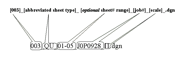
[sheet#]_[abbreviated sheet type]_[optional sheet# by sheet type]_[job#]_[scale]_[optional description].dgn
The only acceptable characters will be capital letters, numbers, or an underscore "_". An underscore "_" will be used as a separation between items
- [sheet#] is a sequential 3 digit number assigned to each sheet. There are two exceptions to the 3 digit convention:
- First, for sheets #001 through #003, all Title Sheets will begin with the number #001, Typical Section Sheets will begin with #002 and Quantity Sheets will begin with number #003.
- Second, for sheets with multiple borders (such as in cross-section (XS) sheets), the naming convention will differ as follows: The type of sheet will be followed by the sheet numbers. The following example shows cross-section sheets 011-015 followed by job #, scale, and optional description: XS_011-015_J0P0928_I5_RP1.dgn. There will be no leading numbers on these file names.
- After sheet(s) #003, sequential numbering shall continue with no duplicate numbers. If a sheet (or sheets) need(s) to be inserted, a sequential letter will follow the number (004, 005, 006, 006A, 006B, 006C, 007, etc.). If more than 26 sheets are required to be inserted, the designer should consider renumbering all contract plans from the insertion point forward.
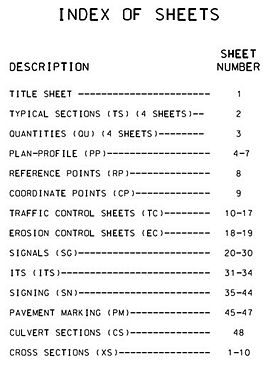
- [abbreviated sheet type] is the 2 lettered abbreviation, identifying a particular kind of sheet (i.e., QU=Quantity Sheet, PP=Plan-Profile Sheet, etc.). These abbreviations are also used in the Index of Sheets on the title sheet and must match.
- [optional sheet# by sheet type] is an optional 2 or 3 digit number, assigned by a designer, within a particular sheet type (i.e., EC_01, EC_02 would be the 1st and 2nd Erosion Control Sheets).
- [job#] is the job number as assigned by the district (i.e., J0P0928).
- [scale] is the scale the MicroStation border was created in for a particular drawing (i.e., I1, I100).
- [optional description] is a description added by the designer to quickly identify components of a project that need to be identified (i.e., STAGE1, 54THSTREET, etc.).
Example Single Quantity Sheet
Example Multiple Quantity Sheet
Example with Optional Description

Example Single Cross-Section Sheet

Example Multiple Cross-Section Sheets

237.13.2 Electronic Design Data
File naming convention for electronic design data files generated from GEOPAK for Roadway Contract Plans shall be as follows:
| Contents File Report | project_data_Summary_report_[job#].XLSX |
| Geometry Files | civil_geometry_[job#].DGN |
| civil_geometry_[job#].XML | |
| civil_geometry_report_[job#].XLSX | |
| MicroStation Files | corridors_[job#].DGN |
| graphical_filters_[job#].DGN | |
| superelevation_[job#].DGN | |
| drainage_[job#].DGN | |
| xs_[job#].DGN | |
| plan_[job#].DGN | |
| profile_[job#].DGN | |
| plan_profile_[job#].DGN | |
| 3D Existing Terrain Models | terrain_existing_[job#].DGN |
| terrain_existing_[job#].XML | |
| survey_[job#].DGN | |
| survey_report_[job#].PDF | |
| survey_coordinate_[job#].CSV | |
| 3D Digital Design Models | proposed_surface_[job#].XML |
237.13.3 Bridge Contract Plans
The file naming convention for all Bridge Contract Plans shall be as follows:
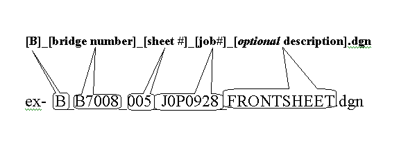
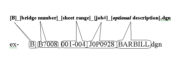
- [B]_[bridge number]_[sheet#]_[job#].dgn
- [B] is the letter “B” for Bridge.
- [bridge number] is the bridge number (i.e., A7005).
- [sheet#] is the number of a particular sheet unique to a bridge number.
- [job#] is the job number as assigned to the project (i.e., J0P0928).
- [optional description] is a description of the sheet information (i.e., BARBILL, FRONTSHEET).
Example Single Bridge Sheet
Example Multiple Bridge Sheets
237.13.4 Example Set of Plans
| 001_TITLE_J0P0928_ITITLESHEET.dgn | 009_SS_02_J0P0928_I20.dgn |
| 002_TS_01_J0P0928_I5_001.dgn | 010_EC_01_J0P0928_I50.dgn |
| 002_TS_02_J0P0928_I5_002.dgn | 011_EC_02_J0P0928_I50.dgn |
| 002_TS_03_J0P0928_I5_003.dgn | 012_EC_03_J0P0928_I50.dgn |
| 002_TS_04-06_J0P0928_I5_004.dgn | 013_CS_01_J0P0928_I10.dgn |
| 002_TS_04-06_J0P0928_I5_005.dgn | 014_CS_02_J0P0928_I10.dgn |
| 002_TS_04-06_J0P0928_I5_006.dgn | B_A6885_001_J0P0928_FrontSheet.dgn |
| 003_QU_01-05_J0P0928_I1_001.dgn | B_A6885_002_J0P0928_CulvertDetails.dgn |
| 003_QU_01-05_J0P0928_I1_002.dgn | B_B7008_003_J0P0928_BarBill.dgn |
| 003_QU_01-05_J0P0928_I1_003.dgn | B_B7008_004_J0P0928_InfoSheets.dgn |
| 003_QU_01-05_J0P0928_I1_004.dgn | XS_001-005_J0P0928_I5_Stage1_001.dgn |
| 003_QU_01-05_J0P0928_I1_005.dgn | XS_001-005_J0P0928_I5_Stage1_002.dgn |
| 003_QU_06_J0P0928_I1.dgn | XS_001-005_J0P0928_I5_Stage1_003.dgn |
| 004_PP_J0P0928_I50_Rte65.dgn | XS_001-005_J0P0928_I5_Stage1_004.dgn |
| 005_PP_J0P0928_I50_Rte65.dgn | XS_001-005_J0P0928_I5_Stage1_005.dgn |
| 006_PP_J0P0928_I50_Rte65.dgn | XS_006-010_J0P0928_I5_Stage1_006.dgn |
| 007_PP_J0P0928_I50_Rte65.dgn | XS_006-010_J0P0928_I5_Stage1_007.dgn |
| 007A_PP_J0P0928_I50_Rte65.dgn | XS_006-010_J0P0928_I5_Stage1_008.dgn |
| 008_SS_01_J0P0928_I20.dgn | XS_006-010_J0P0928_I5_Stage1_009.dgn |
237.13.5 Example Set of Electronic Design Data
| Content's File Report: | J0P0928_contents_file.pdf |
| Geometry File(s): | J0P0928_geometry.gpk |
| J0P0928_geometry.alg | |
| J0P0928]_geometry.xml | |
| Microstation Files: | J0P0928_plan_rte65.dgn |
| J0P0928_profile_ rte65.dgn | |
| J0P0928_xs_ rte65.dgn | |
| J0P0928_drainage_ rte65.dgn | |
| J0P0928_shapes_ rte65.dgn | |
| J0P0928_3D_ rte65.dgn | |
| 3D Existing Terrain Models: | J0P0928_Existing_ rte65.tin |
| J0P0928_Existing_ rte65.dtm | |
| J0P0928_Existing_ rte65.xml | |
| 3D Digital Design Models: | J0P0928_PFG_surface_ rte65.tin |
| J0P0928_PFG_surface_ rte65.dtm | |
| J0P0928_PFG_surface_ rte65.xml | |
| J0P0928_subgrade_surface_ rte65.tin | |
| J0P0928_subgrade_surface_ rte65.dtm | |
| J0P0928_subgrade_surface_ rte65.xml | |
| Final Engineering Design Data: | J0P0928_rte65.rdp |
| J0P0928_ rte65.ird | |
| J0P0928_ rte65.itl |
237.13.6 Index of Sheets
Following is an example of the Index of Sheets on the title sheet:
| DESCRIPTION | SHEET NUMBER |
TITLE SHEET---------------------------------------------------------------------1
TYPICAL SECTIONS (TS) (XX SHEETS)-------------------------------2
QUANTITIES (QU) (XX SHEETS)------------------------------------------3
PLAN-PROFILE (PP)-------------------------------------------------------XX-XX
RIGHT OF WAY (RW)------------------------------------------------------XX-XX
REFERENCE POINTS (RP)----------------------------------------------XX-XX
COORDINATE POINTS (CP)---------------------------------------------XX-XX
SPECIAL SHEETS (SS)---------------------------------------------------XX-XX
TRAFFIC CONTROL SHEETS (TC)------------------------------------XX-XX
EROSION CONTROL SHEETS (EC)----------------------------------XX-XX
LIGHTING (LT)-----------------------------------------------------------------XX-XX
SIGNALS (SG)-----------------------------------------------------------------XX-XX
SIGNING (SN)------------------------------------------------------------------XX-XX
PAVEMENT MARKING (PM)---------------------------------------------XX-XX
CULVERT SECTIONS (CS)------------------------------------------------XX-XX
BRIDGE DRAWINGS (B)
- A####------------------------------------------------------------------------XX-XX
- A####------------------------------------------------------------------------XX-XX
- A####------------------------------------------------------------------------XX-XX
- A####------------------------------------------------------------------------XX-XX
CROSS-SECTIONS (XS)----------------------------------------------------XX-XX


