751.6 General Quantities: Difference between revisions
m →751.6.2 Computation of Estimated Quantities: Per Bridge, guidance added to accommodate new System I, per Sec 1081 |
m Per Bridge, update of links |
||
| Line 1,034: | Line 1,034: | ||
*The perimeter of seal courses | *The perimeter of seal courses | ||
*No excavation shall be figured for piles or bracing | *No excavation shall be figured for piles or bracing | ||
*If there is less than 10 cubic yards of total excavation, no excavation item needs to be listed in the Estimated Quantities. See | *If there is less than 10 cubic yards of total excavation, no excavation item needs to be listed in the Estimated Quantities. See [[751.50 Standard Detailing Notes|EPG 751.50 Standard Detailing Notes]] for the appropriate notes. | ||
'''Classes of Excavation (**)''' | '''Classes of Excavation (**)''' | ||
| Line 1,050: | Line 1,050: | ||
''(*) Soil shall be excavated vertically from the bottom of the footing for footing on pile, 6” above the bottom of the footing for footing on rock and 18” above the bottom of the footing for footing on shale.'' | ''(*) Soil shall be excavated vertically from the bottom of the footing for footing on pile, 6” above the bottom of the footing for footing on rock and 18” above the bottom of the footing for footing on shale.'' | ||
''(**) Use Excavation in Rock if it is anticipated to be more than 10 cu. yard. The designer should check with the Structural Project Manager before calculating the quantity of Excavation in Rock. See | ''(**) Use Excavation in Rock if it is anticipated to be more than 10 cu. yard. The designer should check with the Structural Project Manager before calculating the quantity of Excavation in Rock. See [[#751.6.1 Index of Quantities|EPG 751.6.1 Index of Quantities Bridge]].'' | ||
<center>[[Image:751.6_NIEB_Case_1_A.gif]] | <center>[[Image:751.6_NIEB_Case_1_A.gif]] | ||
| Line 1,162: | Line 1,162: | ||
:Final limits of the roadway and bridge excavation to be coordinated with the bridge plans prior to estimating. | :Final limits of the roadway and bridge excavation to be coordinated with the bridge plans prior to estimating. | ||
:See | :See [[751.50 Standard Detailing Notes|EPG 751.50 Standard Detailing Notes]] for the appropriate notes. | ||
| Line 1,175: | Line 1,175: | ||
<br/>Excavation of 18" adjacent to the removal of culvert ends for purpose of extending the culvert will not be considered excavation and is considered part of removal. (Refer to Sec 206) | <br/>Excavation of 18" adjacent to the removal of culvert ends for purpose of extending the culvert will not be considered excavation and is considered part of removal. (Refer to Sec 206) | ||
<br/> | <br/> | ||
<br/>See | <br/>See [[751.50 Standard Detailing Notes|EPG 751.50 Standard Detailing Notes]] for the appropriate notes. | ||
<center>'''Excavation Limits: Culverts'''</center> | <center>'''Excavation Limits: Culverts'''</center> | ||
Revision as of 09:17, 20 June 2011
751.6.1 Index of Quantities
The following list of pay items shall be used as a guide when preparing the Table of Estimated Quantities. The pay items shall be listed on the plans in numerical order according to the Item Number. The Item Number is for information only and is not to be listed in the Table of Estimated Quantities. For pay items not listed, see the Plans Review Section.
| Item Number | Accuracy | Units | Item Description |
|---|---|---|---|
| Indicates this item shall be used only as approved by Plans Review Section. | |||
| 206-10.00 206-10.05 |
5.0 | cu. yard cu. meter |
Class 1 Excavation |
| 206-10.03 206-10.07 |
1.0 | cu. yard cu. meter |
Class 1 Excavation in Rock (*) |
| 206-20.00 206-20.05 |
1.0 | cu. yard cu. meter |
Class 2 Excavation |
| 206-20.03 206-20.07 |
1.0 | cu. yard cu. meter |
Class 2 Excavation in Rock (*) |
| 206-33.00 206-33.05 |
5.0 | cu. yard cu. meter |
Class 4 Excavation |
| 206-34.00 206-34.05 |
1.0 | cu. yard cu. meter |
Class 4 Excavation in Rock (*) |
| * Note: Use when cross-sections indicate rock will be encountered and quantity is more than 10 cu. Yard. If there is less than 10 cu. yards of total excavation in rock, no Excavation in Rock pay items should be listed in the Estimated Quantities. Excavation in rock will be paid in accordance with Sec 109. Check with Project Manager when computing this item. | |||
| 206-36.00 206-36.05 |
1.0 0.5 |
linear foot meter |
Supplementary Foundation Test Holes (NX) |
| 206-36.10 206-36.15 |
1.0 0.5 |
linear foot meter |
Supplementary Cored Holes |
| 206-40.00 206-40.05 |
1.0 | cu. yard cu. meter |
Porous Backfill |
| 206-55.00 | 1.0 | lump sum | Temporary Shoring |
| 206-60.02 to 206-60.12 |
1.0 | lump sum | Cofferdams - Bent xx Note: Use a separate pay item for each bent. Item numbers established for only Bent 2 thru Bent 12. |
| 206-99.01 | 1.0 | lump sum | Misc. |
| 206-99.02 | 1.0 | each | Misc. |
| 206-99.03 206-99.03M |
1.0 0.5 |
linear foot meter |
Misc. |
| 206-99.04 | 1.0 | sq. foot | Misc. |
| 206-99.05 206-99.05M |
0.1 | sq. yard sq. meter |
Misc. |
| 206-99.07 206-99.07M |
1.0 | cu. yard cu. meter |
Misc. |
| 216-05.00 | 1.0 | lump sum | Removal of Bridges |
| 216-05.01 | 1.0 | lump sum | Match Marking and Storing Superstructure |
| 216-10.00 216-10.50 |
1.0 | sq. yard sq. meter |
Scarification of Bridge Decks Note: Do not use on concrete overlay removals. |
| 216-15.00 216-15.50 |
1.0 0.1 |
sq. foot sq. meter |
Removal of Seal Coat Note: Do not use for unbonded seal coat removal. |
| 216-15.01 216-15.51 |
1.0 0.1 |
sq. foot sq. meter |
Removal of Asphalt Wearing Surface |
| 216-15.02 216-15.52 |
1.0 0.1 |
sq. foot sq. meter |
Removal of Concrete Wearing Surface Note: Use for all concrete wearing surfaces. |
| 216-20.00 216-20.50 |
1.0 0.5 |
linear foot meter |
Removal and Storage of Existing Bridge Rails |
| 216-25.00 216-25.50 |
1.0 0.1 |
sq. foot sq. meter |
Removal of Existing Bridge Decks |
| 216-30.00 216-30.50 |
1.0 0.1 |
sq. foot sq. meter |
Partial Removal of Existing Bridge Decks |
| 216-35.00 | 1.0 | lump sum | Partial Removal of Culvert Concrete |
| 216-35.01 | 1.0 | lump sum | Partial Removal of Culvert-Bridge Concrete |
| 216-35.02 | 1.0 | lump sum | Partial Removal of Substructure Concrete |
| 216-40.00 216-40.50 |
1.0 0.5 |
linear foot meter |
Curb Removal Note: Use for just removal of curbs including for thrie beam installation. |
| 216-45.00 216-45.50 |
1.0 0.5 |
linear foot meter |
Removal of Existing Expansion Joints & Adjacent Concrete Note: Also use Concrete and Reinforcing Steel pay items for replacement of expansion joint system. |
| 216-50.00 216-50.50 |
1.0 0.5 |
linear foot meter |
Removal of Existing Expansion Joint Seal or Sealant Note: Also use Concrete and Reinforcing Steel pay items for replacement of expansion joint system. |
| 216-55.00 | 1.0 | lump sum | Removal of Cathodic Protection System |
| 216-99.01 | 1.0 | lump sum | Misc. |
| 216-99.03 216-99.03M |
1.0 0.5 |
linear foot meter |
Misc. |
| 216-99.04 | 1.0 | sq. foot | Misc. |
| 216-99.05 216-99.05M |
0.1 | sq. yard sq. meter |
Misc. |
| 403-10.50 403-10.55 |
1.0 | sq. yard sq. meter |
Alternate Asphaltic Concrete Wearing Surface (Bridge) |
| 407-10.05 407-10.00 |
10.0 50.0 |
gallon liter |
Tack Coat |
| 409-40.00 409-40.05 |
1.0 | sq. yard sq. meter |
Seal Coat, Grade A |
| 409-40.20 409-40.25 |
1.0 | sq. yard sq. meter |
Seal Coat, Grade C |
| 503-10.10 503-10.15 |
1.0 | sq. yard sq. meter |
Bridge Approach Slab (Bridge) |
| 505-00.01 505-00.05 |
1.0 | sq. yard sq. meter |
Alternate Concrete Wearing Surface |
| 505-10.00 505-10.50 |
1.0 | sq. yard sq. meter |
Low Slump Concrete Wearing Surface |
| 505-20.00 505-20.50 |
1.0 | sq. yard sq. meter |
Latex Modified Concrete Wearing Surface |
| 505-20.01 505-20.51 |
1.0 | sq. yard sq. meter |
Latex Modified High Early Strength Concrete Wearing Surface |
| 505-30.00 505-30.50 |
1.0 | sq. yard sq. meter |
Silica Fume Concrete Wearing Surface |
| 505-99.05 505-99.05M |
1.0 | sq. yard sq. meter |
Misc. |
| 605-20.10A 605-20.15A |
1.0 0.5 |
linear foot meter |
Structural Underdrain |
| 607-10.50 607-15.50 |
1.0 0.5 |
linear foot meter |
Chain-Link Fence (Retaining Walls) |
| 607-10.54 607-15.54 |
1.0 0.5 |
linear foot meter |
(42 in.) Property Fence (Structures) 1065 mm Property Fence (Structures) |
| 607-10.55 607-15.55 |
1.0 0.5 |
linear foot meter |
(60 in.) Property Fence (Structures) 1525 mm Property Fence (Structures) |
| 607-10.56 607-15.56 |
1.0 0.5 |
linear foot meter |
(72 in.) Property Fence (Structures) 1830 mm Property Fence (Structures) |
| 607-10.57 607-15.57 |
1.0 0.5 |
linear foot meter |
(84 in.) Property Fence (Structures) 2135 mm Property Fence (Structures) |
| 607-10.58 607-15.58 |
1.0 0.5 |
linear foot meter |
(96 in.) Property Fence (Structures) 2440 mm Property Fence (Structures) |
| 607-10.60 607-15.60 |
1.0 0.5 |
linear foot meter |
Pedestrian Fence (Structures) Pedestrian Fence (Structures) |
| 607-10.65 607-15.65 |
1.0 0.5 |
linear foot meter |
(60 in.) Pedestrian Fence (Structures) 1525 mm Pedestrian Fence (Structures) |
| 607-10.66 607-15.66 |
1.0 0.5 |
linear foot meter |
(72 in.) Pedestrian Fence (Structures) 1830 mm Pedestrian Fence (Structures) |
| 607-10.67 607-15.67 |
1.0 0.5 |
linear foot meter |
(112 in.) Curved Top Pedestrian Fence (Structures) 2800 mm Curved Top Pedestrian Fence (Structures) |
| 607-99.03 607-99.03M |
1.0 0.5 |
linear foot meter |
Misc. |
| 615-10.05 | 1.0 | lump sum | Water Transportation for Engineer |
| 623-30.00 623-30.05 |
1.0 | sq. yard sq. meter |
Epoxy Polymer Concrete Overlay |
| 623-40.00 623-40.05 |
1.0 0.05 |
cu. foot cu. meter |
Polymer Concrete |
| 623-99.05 623-99.05M |
1.0 | sq. yard sq. meter |
Misc. |
| 701-11.00 701-11.20 |
0.10 0.05 |
linear foot meter |
Drilled Shafts (1 ft. 0 in. Dia.) Drilled Shafts (300 mm Dia.) |
| 701-11.01 701-11.21 |
0.10 0.05 |
linear foot meter |
Drilled Shafts (1 ft. 6 in. Dia.) Drilled Shafts (450 mm Dia.) |
| 701-11.02 701-11.22 |
0.10 0.05 |
linear foot meter |
Drilled Shafts (2 ft. 0 in. Dia.) Drilled Shafts (600 mm Dia.) |
| 701-11.03 701-11.23 |
0.10 0.05 |
linear foot meter |
Drilled Shafts (2 ft. 6 in. Dia.) Drilled Shafts (750 mm Dia.) |
| 701-11.04 701-11.24 |
0.10 0.05 |
linear foot meter |
Drilled Shafts (3 ft. 0 in. Dia.) Drilled Shafts (900 mm Dia.) |
| 701-11.05 701-11.25 |
0.10 0.05 |
linear foot meter |
Drilled Shafts (3 ft. 6 in. Dia.) Drilled Shafts (1050 mm Dia.) |
| 701-11.06 701-11.26 |
0.10 0.05 |
linear foot meter |
Drilled Shafts (4 ft. 0 in. Dia.) Drilled Shafts (1200 mm Dia.) |
| 701-11.07 701-11.27 |
0.10 0.05 |
linear foot meter |
Drilled Shafts (4 ft. 6 in. Dia.) Drilled Shafts (1350 mm Dia.) |
| 701-11.08 701-11.28 |
0.10 0.05 |
linear foot meter |
Drilled Shafts (5 ft. 0 in. Dia.) Drilled Shafts (1500 mm Dia.) |
| 701-11.09 701-11.29 |
0.10 0.05 |
linear foot meter |
Drilled Shafts (5 ft. 6 in. Dia.) Drilled Shafts (1650 mm Dia.) |
| 701-11.10 701-11.30 |
0.10 0.05 |
linear foot meter |
Drilled Shafts (6 ft. 0 in. Dia.) Drilled Shafts (1800 mm Dia.) |
| 701-11.11 701-11.31 |
0.10 0.05 |
linear foot meter |
Drilled Shafts (6 ft. 6 in. Dia.) Drilled Shafts (1950 mm Dia.) |
| 701-11.12 701-11.32 |
0.10 0.05 |
linear foot meter |
Drilled Shafts (7 ft. 0 in. Dia.) Drilled Shafts (2100 mm Dia.) |
| 701-11.13 701-11.33A |
0.10 0.05 |
linear foot meter |
Drilled Shafts (7 ft. 6 in. Dia.) Drilled Shafts (2250 mm Dia.) |
| 701-11.14 701-11.34A |
0.10 0.05 |
linear foot meter |
Drilled Shafts (8 ft. 0 in. Dia.) Drilled Shafts (2400 mm Dia.) |
| 701-11.15 701-11.35A |
0.10 0.05 |
linear foot meter |
Drilled Shafts (8 ft. 6 in. Dia.) Drilled Shafts (2550 mm Dia.) |
| 701-11.16 701-11.36 |
0.10 0.05 |
linear foot meter |
Drilled Shafts (9 ft. 0 in. Dia.) Drilled Shafts (2700 mm Dia.) |
| 701-11.17 701-11.37 |
0.10 0.05 |
linear foot meter |
Drilled Shafts (9 ft. 6 in. Dia.) Drilled Shafts (2850 mm Dia.) |
| 701-11.18 701-11.38 |
0.10 0.05 |
linear foot meter |
Drilled Shafts (10 ft. 0 in. Dia.) Drilled Shafts (3000 mm Dia.) |
| 701-12.00 701-12.20 |
0.10 0.05 |
linear foot meter |
Rock Sockets (1 ft. 0 in. Dia.) Rock Sockets (300 mm Dia.) |
| 701-12.01 701-12.21 |
0.10 0.05 |
linear foot meter |
Rock Sockets (1 ft. 6 in. Dia.) Rock Sockets (450 mm Dia.) |
| 701-12.02 701-12.22 |
0.10 0.05 |
linear foot meter |
Rock Sockets (2 ft. 0 in. Dia.) Rock Sockets (600 mm Dia.) |
| 701-12.03 701-12.23 |
0.10 0.05 |
linear foot meter |
Rock Sockets (2 ft. 6 in. Dia.) Rock Sockets (750 mm Dia.) |
| 701-12.04 701-12.24 |
0.10 0.05 |
linear foot meter |
Rock Sockets (3 ft. 0 in. Dia.) Rock Sockets (900 mm Dia.) |
| 701-12.05 701-12.25 |
0.10 0.05 |
linear foot meter |
Rock Sockets (3 ft. 6 in. Dia.) Rock Sockets (1050 mm Dia.) |
| 701-12.06 701-12.26 |
0.10 0.05 |
linear foot meter |
Rock Sockets (4 ft. 0 in. Dia.) Rock Sockets (1200 mm Dia.) |
| 701-12.07 701-12.27 |
0.10 0.05 |
linear foot meter |
Rock Sockets (4 ft. 6 in. Dia.) Rock Sockets (1350 mm Dia.) |
| 701-12.08 701-12.28A |
0.10 0.05 |
linear foot meter |
Rock Sockets (5 ft. 0 in. Dia.) Rock Sockets (1500 mm Dia.) |
| 701-12.09 701-12.29A |
0.10 0.05 |
linear foot meter |
Rock Sockets (5 ft. 6 in. Dia.) Rock Sockets (1650 mm Dia.) |
| 701-12.10 701-12.30A |
0.10 0.05 |
linear foot meter |
Rock Sockets (6 ft. 0 in. Dia.) Rock Sockets (1800 mm Dia.) |
| 701-12.11 701-12.31A |
0.10 0.05 |
linear foot meter |
Rock Sockets (6 ft. 6 in. Dia.) Rock Sockets (1950 mm Dia.) |
| 701-12.12 701-12.32A |
0.10 0.05 |
linear foot meter |
Rock Sockets (7 ft. 0 in. Dia.) Rock Sockets (2100 mm Dia.) |
| 701-12.13 701-12.33A |
0.10 0.05 |
linear foot meter |
Rock Sockets (7 ft. 6 in. Dia.) Rock Sockets (2250 mm Dia.) |
| 701-12.14 701-12.34A |
0.10 0.05 |
linear foot meter |
Rock Sockets (8 ft. 0 in. Dia.) Rock Sockets (2400 mm Dia.) |
| 701-12.15 701-12.35A |
0.10 0.05 |
linear foot meter |
Rock Sockets (8 ft. 6 in. Dia.) Rock Sockets (2550 mm Dia.) |
| 701-12.16 701-12.36A |
0.10 0.05 |
linear foot meter |
Rock Sockets (9 ft. 0 in. Dia.) Rock Sockets (2700 mm Dia.) |
| 701-12.17 701-12.37 |
0.10 0.05 |
linear foot meter |
Rock Sockets (9 ft. 6 in. Dia.) Rock Sockets (2850 mm Dia.) |
| 701-13.00 | 1.0 | each | Supplementary Television Camera Inspection |
| 701-14.00 701-14.50 |
0.10 0.05 |
linear foot meter |
Foundation Inspection Holes |
| 701-15.00 701-15.50 |
0.10 0.05 |
linear foot meter |
Concrete Coring |
| 701-16.00 | 1 | each | Sonic Logging Testing |
| 701-17.00 | 1 | each | Drilled Shaft Load Tests |
| 701-99.01 | 1.0 | lump sum | Misc. |
| 701-99.02 | 1.0 | each | Misc. |
| 701-99.03 701-99.03M |
0.1 0.05 |
linear foot meter |
Misc. |
| 702-10.10 702-05.10 |
1.0 0.5 |
linear foot meter |
Structural Steel Piles (10 in.) Structural Steel Piles (250 mm) |
| 702-10.12 702-05.12 |
1.0 0.5 |
linear foot meter |
Structural Steel Piles (12 in.) Structural Steel Piles (310 mm) |
| 702-10.14 702-05.14 |
1.0 0.5 |
linear foot meter |
Structural Steel Piles (14 in.) Structural Steel Piles (360 mm) |
| 702-11.14 702-11.35 |
1.0 0.5 |
linear foot meter |
Cast-In-Place Concrete Piles (14 in.) 350 mm Cast-In-Place Concrete Piles |
| 702-11.16 | 1.0 | linear foot | Cast-In-Place Concrete Piles (16 in.) |
| 702-11.20 702-11.50 |
1.0 0.5 |
linear foot meter |
Cast-In-Place Concrete Piles (20 in.) 500 mm Cast-In-Place Concrete Piles |
| 702-11.24 702-11.60 |
1.0 0.5 |
linear foot meter |
Cast-In-Place Concrete Piles (24 in.) 600 mm Cast-In-Place Concrete Piles |
| 702-30.00 702-30.05 |
1.0 0.5 |
linear foot meter |
Test Piles |
| 702-40.00 | 1.0 | each | Loading Tests |
| 702-50.01 | 1.0 | each | Dynamic Pile Testing |
| 702-50.02 | 1.0 | each | Pile Wave Analysis |
| 702-50.03 702-50.53 |
1.0 0.5 |
linear foot meter |
Pilot Hole |
| 702-60.00 702-60.05 |
1.0 0.5 |
linear foot meter |
Pre-Bore for Piling Note: Compute this to nearest foot or 0.5 meter for each hole.. |
| 702-70.00 | 1.0 | each | Pile Point Reinforcement |
| 702-99.02 | 1.0 | each | Misc. |
| 702-99.03 702-99.03M |
1.0 0.5 |
linear foot meter |
Misc. |
| 703-10.04 703-10.54 |
1.0 | sq. yard sq. meter |
Diamond Grinding |
| 703-10.05 703-10.55 |
1.0 | sq. yard sq. meter |
Transverse Diamond Grooving |
| 703-20.00 703-20.11A |
0.10 | cu. yard cu. meter |
Class B Concrete (Culverts-Bridge) |
| 703-20.01 703-20.12A |
0.10 | cu. yard cu. meter |
Class B Concrete (Culverts) |
| 703-20.02 703-20.13 |
0.10 | cu. yard cu. meter |
Class B Concrete (Misc) |
| 703-20.03 703-20.14 |
0.10 | cu. yard cu. meter |
Class B Concrete (Substructure) |
| 703-20.09 703-20.15 |
0.10 | cu. yard cu. meter |
Class B Concrete (Retaining Walls) |
| 703-20.25 | 1.0 | each | Deadman Anchorage Assembly |
| 703-30.01 703-30.11 |
0.10 | cu. yard cu. meter |
Seal Concrete |
| 703-40.01 703-40.00 |
0.10 | cu. yard cu. meter |
Class B-1 Concrete |
| 703-40.02 703-40.11 |
0.10 | cu. yard cu. meter |
Class B-1 Concrete (Superstructure on Steel and Concrete) |
| 703-40.03 703-40.12 |
0.10 | cu. yard cu. meter |
Class B-1 Concrete (Substructure) |
| 703-40.04 703-40.13 |
0.10 | cu. yard cu. meter |
Class B-1 Concrete (Superstructure on Steel) |
| 703-40.05 703-40.14 |
0.10 | cu. yard cu. meter |
Class B-1 Concrete (Superstructure Voided Slabs) |
| 703-40.06 703-40.15 |
0.10 | cu. yard cu. meter |
Class B-1 Concrete (Superstructure Concrete Box Girder) |
| 703-40.07 703-40.16 |
0.10 | cu. yard cu. meter |
Class B-1 Concrete (Superstructure Concrete Tee Girder) |
| 703-40.08 703-40.17 |
0.10 | cu. yard cu. meter |
Class B-1 Concrete (Superstructure Solid Slab) |
| 703-40.09 703-40.18 |
0.10 | cu. yard cu. meter |
Class B-1 Concrete (Retaining Walls) |
| 703-40.10 703-40.19 |
0.10 | cu. yard cu. meter |
Class B-1 Concrete (Superstructure Concrete on I-Girder) |
| 703-40.20 703-40.25 |
0.10 | cu. yard cu. meter |
Class B-1 Concrete (Superstructure) |
| 703-40.30 703-40.35 |
0.10 | cu. yard cu. meter |
Class B-1 Concrete (Barrier Curbs) |
| 703-40.40 703-40.21 |
0.10 | cu. yard cu. meter |
Class B-1 Concrete (Culverts-Bridge) |
| 703-40.41 703-40.22 |
0.10 | cu. yard cu. meter |
Class B-1 Concrete (Culverts) |
| 703-42.02 703-43.02 |
0.10 | cu. yard cu. meter |
Class B-2 Concrete (Superstructure on Steel and Concrete) |
| 703-42.04 703-43.04 |
0.10 | cu. yard cu. meter |
Class B-2 Concrete (Superstructure on Steel) |
| 703-42.05 703-43.05 |
0.10 | cu. yard cu. meter |
Class B-2 Concrete (Superstructure Voided Slabs) |
| 703-42.06 703-43.06 |
0.10 | cu. yard cu. meter |
Class B-2 Concrete (Superstructure Concrete Box Girder) |
| 703-42.07 703-43.07 |
0.10 | cu. yard cu. meter |
Class B-2 Concrete (Superstructure Concrete Tee Girder) |
| 703-42.08 703-43.08 |
0.10 | cu. yard cu. meter |
Class B-2 Concrete (Superstructure Solid Slab) |
| 703-42.10 703-43.10 |
0.10 | cu. yard cu. meter |
Class B-2 Concrete (Superstructure Concrete on I Girder) |
| 703-42.11 703-43.11 |
0.10 | cu. yard cu. meter |
Class B-2 Concrete (Superstructure Concrete on Box Girder) |
| 703-42.12 703-43.12 |
1.0 | sq. yard sq. meter |
Slab on Steel |
| 703-42.13 703-43.13 |
1.0 | sq. yard sq. meter |
Slab on Concrete I-Girder |
| 703-42.14 703-43.14 |
0.10 | cu. yard cu. meter |
Class B-2 Concrete |
| 703-42.15 703-43.15 |
1.0 0.5 |
linear foot meter |
Safety Barrier Curb |
| 703-42.26 703-43.26 |
1.0 | sq. yard sq. meter |
Reinforced Concrete Slab Overlay Note: For prestressed voided slab beams, box girders and double-tees. |
| 703-42.18 703.43.18 |
1.0 | sq. yard sq. meter |
Slab on Concrete Bulb-Tee Girder |
| 703-42.19A 703-43.19A |
1.0 0.5 |
linear foot meter |
Barrier Curb (Type D) |
| 703-42.20 703-43.25 |
1.0 | sq. yard sq. meter |
Slab on Semi-Deep Abutment |
| 703-42.30 703-43.35 |
0.10 | cu. yard cu. meter |
Class B-2 Concrete (Post -Tensioned Overlay) |
| 703-44.10 703-44.15 |
1.0 0.5 |
linear foot meter |
Median Barrier Curb |
| 703-44.11 703-44.16 |
1.0 0.5 |
linear foot meter |
Median Barrier Curb (Type C) |
| 703-44.12 703-44.17 |
1.0 0.5 |
linear foot meter |
Median Barrier Curb Transition |
| 703-44.13 703-44.18 |
1.0 0.5 |
linear foot meter |
Median Barrier Curb Transition (Type C) |
| 703-44.20 703-44.25A |
1.0 0.1 |
sq. foot sq. meter |
Raised Median Barrier |
| 703-44.30 703-44.35A |
1.0 0.1 |
sq. foot sq. meter |
Sidewalk (Bridges) |
| 703-45.35 703-45.36 |
1.0 0.5 |
linear foot meter |
Curb Modification |
| 703-46.00 703-46.50 |
1.0 0.5 |
linear foot meter |
Curb Blockout |
| 703-46.10 703-46.60 |
1.0 0.5 |
linear foot meter |
Corral Curb |
| 703-46.20 703-46.70 |
1.0 | sq. yard sq. meter |
Form Liners |
| 703-60.00A 703-60.10A |
0.10 | cu. yard cu. meter |
Class A-1 Concrete |
| 703-99.01 | 1.0 | lump sum | Misc. |
| 703-99.02 | 1.0 | each | Misc. |
| 703-99.03 703-99.03M |
1.0 0.5 |
linear foot meter |
Misc. |
| 703-99.04 | 1.0 | sq. foot | Misc. |
| 703-99.05 703-99.05M |
0.1 | sq. yard sq. meter |
Misc. |
| 703-99.07 703-99.07M |
0.1 | cu. yard cu. meter |
Misc. |
| 704-01.01 704-01.51 |
1.0 0.1 |
sq. foot sq. meter |
Substructure Repair (Formed) |
| 704-01.02 704-01.52 |
1.0 0.1 |
sq. foot sq. meter |
Substructure Repair (Unformed) |
| 704-01.03 704-01.53 |
1.0 0.1 |
sq. foot sq. meter |
Superstructure Repair (Unformed) |
| 704-01.04 704-01.54 |
50.0* 5.0* |
sq. foot sq. meter |
Repairing Concrete Deck (Half-Soling) |
| 704-01-05 704-01-55 |
1.0* | cu. yard cu. meter |
Partial Depth Repair |
| 704-01.06 704-01.56 |
50.0* 5.0* |
sq. foot sq. meter |
Full Depth Repair |
| 704-01.07 704-01.57 |
1.0 0.5 |
linear foot meter |
Slab Edge Repair (Bridges) |
| 704-01.08 704-01.58 |
50.0* 5.0* |
sq. foot sq. meter |
Modified Deck Repair |
| 704-01.09 704-01.59 |
1.0 | sq. yard sq. meter |
Total Surface Hydro Demolition |
| 704-01.10 704-01.60 |
1.0 0.5 |
linear foot meter |
Epoxy Pressure Injecting |
| 704-01.11 704-01.61 |
1.0 | each | Deck Girder End Repair |
| 704-01.12 704-01.62 |
50.0* 5.0* |
sq. foot sq. meter |
Deck Repair with Void Tube Replacement |
| 704-01.13 | 1.0 | sq. foot | Clean and Epoxy Seal |
| *Note: Round quantity up to nearest multiple of 50 sq. ft (5 m2) or 1 cu. yard (1 m3) | |||
| 704-99.01 | 1.0 | lump sum | Misc. |
| 704-99.02 | 1.0 | each | Misc. |
| 704-99.03 704-99.03M |
1.0 0.5 |
linear foot meter |
Misc. |
| 704-99.04 | 1.0 | sq. foot | Misc. |
| 704-99.05 704-99.05M |
1.0 0.1 |
sq. yard sq. meter |
Misc. |
| 704-99.07 704-99.07M |
0.1 | cu. yard cu. meter |
Misc. |
| 705-60.00 | 1.0 | linear foot | Type 2 (32 in.), Prestressed Concrete I-Girder |
| 705-60.01 | 1.0 | linear foot | Type 3 (39 in.), Prestressed Concrete I-Girder |
| 705-60.02 | 1.0 | linear foot | Type 4 (45 in.), Prestressed Concrete I-Girder |
| 705-60.03 | 1.0 | linear foot | Type 6 (54 in.), Prestressed Concrete I-Girder |
| 705-60.10 | 1.0 | linear foot | Type 8 (63 in.), Prestressed Concrete Bulb-Tee Girder |
| 705-60.11 | 1.0 | linear foot | Type 7 (72 in.), Prestressed Concrete Bulb-Tee Girder |
| 705-60.21 | 1.0 | linear foot | NU 35, Prestressed Concrete NU-Girder |
| 705-60.22 | 1.0 | linear foot | NU 43, Prestressed Concrete NU-Girder |
| 705-60.23 | 1.0 | linear foot | NU 53, Prestressed Concrete NU-Girder |
| 705-60.24 | 1.0 | linear foot | NU 63, Prestressed Concrete NU-Girder |
| 705-60.25 | 1.0 | linear foot | NU 70, Prestressed Concrete NU-Girder |
| 705-60.30 | 1.0 | linear foot | 11 in., Prestressed Concrete Solid Slab Beam |
| 705-60.31 | 1.0 | linear foot | 12 in., Prestressed Concrete Solid Slab Beam |
| 705-60.41 | 1.0 | linear foot | 15 in., Prestressed Concrete Voided Slab Beam |
| 705-60.42 | 1.0 | linear foot | 17 in., Prestressed Concrete Voided Slab Beam |
| 705-60.43 | 1.0 | linear foot | 18 in., Prestressed Concrete Voided Slab Beam |
| 705-60.44 | 1.0 | linear foot | 21 in., Prestressed Concrete Voided Slab Beam |
| 705-60.50 | 1.0 | linear foot | 27 in., Prestressed Concrete Box Girder Beam |
| 705-60.51 | 1.0 | linear foot | 33 in., Prestressed Concrete Box Girder Beam |
| 705-60.52 | 1.0 | linear foot | 39 in., Prestressed Concrete Box Girder Beam |
| 705-60.53 | 1.0 | linear foot | 42 in., Prestressed Concrete Box Girder Beam |
| 705-60.61 | 1.0 | linear foot | Type 16, Prestressed Concrete Dbl-Tee |
| 705-60.62 | 1.0 | linear foot | Type 22, Prestressed Concrete Dbl-Tee |
| 705-60.63 | 1.0 | linear foot | Type 30, Prestressed Concrete Dbl-Tee |
| 705-99.01 | 1.0 | lump sum | Misc. |
| 705-99.02 | 1.0 | each | Misc. |
| 705-99.03 705-99.03M |
1.0 0.5 |
linear foot meter |
Misc. |
| 705-99.04 | 1.0 | sq. foot | Misc. |
| 705-99.05 705-99.05M |
1.0 0.1 |
sq. yard sq. meter |
Misc. |
| 706-10.00 706-10.05 |
10 5 |
pound kilogram |
Reinforcing Steel |
| 706-10.20 706-10.25 |
10 5 |
pound kilogram |
Reinforcing Steel (Culverts-Bridge) |
| 706-10.30 706-10.35 |
10 5 |
pound kilogram |
Reinforcing Steel (Culverts) |
| 706-10.40 706-10.45 |
10 5 |
pound kilogram |
Reinforcing Steel (Retaining Wall) |
| 706-10.60 706-10.65 |
10 5 |
pound kilogram |
Reinforcing Steel (Bridges) |
| 706-10.70 | 1.0 | each | Mechanical Bar Splice |
| 706-99.11 706-99.11M |
10 5 |
pound kilogram |
Misc. |
| 707-10.00 | 1.0 | lump sum | Conduit System on Structure |
| 707-10.30 | 1.0 | lump sum | Conduit System on Structure (Telephone) |
| 707-10.40 | 1.0 | lump sum | Cathodic Protection System |
| 707-99.01 | 1.0 | lump sum | Misc. |
| 707-99.02 | 1.0 | each | Misc. |
| 710-10.00 710-10.05 |
10 5 |
pound kilogram |
Reinforcing Steel (Epoxy Coated) |
| 710-99.11 710-99.11M |
10 5 |
pound kilogram |
Misc. |
| 711-01.00 | 1 | lump sum | Protective Coating – Concrete Bents and Piers (Urethane)Note: Tar appearance |
| 711-02.00 | 1 | lump sum | Protective Coating – Concrete Bents and Piers (Epoxy)Note: Clear appearance |
| 711-03.00 | 1 | lump sum | Concrete and Masonry Protection System |
| 711-04.00 | 1 | lump sum | Sacrificial Graffiti Protection System |
| 711-05.00 | 1 | lump sum | Temporary Coating – Concrete Bents and Piers (Weathering Steel) |
| 711-06.00 | 1 | lump sum | Aesthetic Concrete Stain |
| 711-07.00 | 1.0 | sq. yard | Penetrating Sealer |
| 711-10.00 711-10.50 |
1.0 | sq. yard sq. meter |
Waterproofing |
| 711-10.01 711-10.51 |
1.0 | sq. yard sq. meter |
Waterproofing Membrane |
| 711-99.01 | 1 | lump sum | Misc. |
| 711-99.04 | 1.0 | sq. foot | Misc. |
| 711-99.05 711-99.05M |
1.0 | sq. yard sq. meter |
Misc. |
| 712-09.00 712-09.05A |
1.0 0.5 |
linear foot meter |
Expansion Device (Finger Plate) |
| 712-09.15 712-09.20A |
1.0 0.5 |
linear foot meter |
Expansion Device (Flat Plate) |
| 712-10.00 712-10.05 |
10 5 |
pound kilogram |
Fabricated Structural Carbon Steel (Misc.) |
| 712-10.10 712-10.15 |
10 5 |
pound kilogram |
Fabricated Structural Carbon Steel (I-Beam) |
| 712-10.20 712-10.25 |
10 5 |
pound kilogram |
Fabricated Structural Carbon Steel (Plate Girder) |
| 712-10.30 712-10.35 |
10 5 |
pound kilogram |
Fabricated Structural Carbon Steel (Trusses) |
| 712-10.40 712-10.45 |
10 5 |
pound kilogram |
Fabricated Structural Carbon Steel (Concrete) |
| 712-10.50 712-10.55 |
10 5 |
pound kilogram |
Fabricated Structural Carbon Steel (Box Girder) |
| 712-10.60 | 1.0 | lump sum | Fabricated Sign Support Brackets |
| 712-11.00 712-11.05 |
10 5 |
pound kilogram |
Fabricated Structural Low Alloy Steel (Misc.) |
| 712-11.11 712-11.12 |
10 5 |
pound kilogram |
Fabricated Structural Low Alloy Steel (I-Beam)A709, Grade 50 Fabricated Structural Low Alloy Steel (I-Beam)A-709M, Grade 345 |
| 712-11.13 712-11.15 |
10 5 |
pound kilogram |
Fabricated Structural Low Alloy Steel (I-Beam) A709, Grade 50W Fabricated Structural Low Alloy Steel (I-Beam) A709M, Grade 345W |
| 712-11.21 712-11.20 |
10 5 |
pound kilogram |
Fabricated Structural Low Alloy Steel (Plate Girder) A709, Grade 50 Fabricated Structural Low Alloy Steel (Plate Girder) A709M, Grade 345 |
| 712-11.22 712-11.25 |
10 5 |
pound kilogram |
Fabricated Structural Low Alloy Steel (Plate Girder) A709, Grade 50W Fabricated Structural Low Alloy Steel (Plate Girder) A709M, Grade 345W |
| 712-11.23 712-11.26 |
10 5 |
pound kilogram |
Fabricated Structural Low Alloy Steel (Plate Girder) A709 Grade HPS70W Fabricated Structural Low Alloy Steel (Plate Girder) A709M Grade HPS485W |
| 712-11.24 712-11.27 |
10 5 |
pound kilogram |
Fabricated Structural Low Alloy Steel (Plate Girder) A709 Grade HPS50W Fabricated Structural Low Alloy Steel (Plate Girder) A709M Grade HPS345W |
| 712-11.30 712-11.35 |
10 5 |
pound kilogram |
Fabricated Structural Low Alloy Steel (Trusses) |
| 712-11.40 712-11.45 |
10 5 |
pound kilogram |
Fabricated Structural Low Alloy Steel (Concrete) |
| 712-11.51 712-11.50 |
10 5 |
pound kilogram |
Fabricated Structural Low Alloy Steel (Box Girder) A709, Grade 50 Fabricated Structural Low Alloy Steel (Box Girder) A709M, Grade 345 |
| 712-11.52 712-11.55 |
10 5 |
pound kilogram |
Fabricated Structural Low Alloy Steel (Box Girder) A709, Grade 50W Fabricated Structural Low Alloy Steel (Box Girder) A709M, Grade 345W |
| 712-11.60 712-11.65 |
1.0 0.1 |
sq. foot sq. meter |
Steel Grid Floor (Half Concrete Filled) |
| 712-11.61 712-11.66 |
1.0 0.1 |
sq. foot sq. meter |
Steel Grid Floor (Concrete Filled) |
| 712-12.50 | 1.0 | lump sum | Strengthening Existing Stringers |
| 712-13.00 712-13.05 |
10 5 |
pound kilogram |
Fabricated Structural Steel Bearings |
| 712-20.00 712-20.05 |
10 5 |
pound kilogram |
Carbon Steel Castings |
| 712-22.00 712-22.05 |
10 5 |
pound kilogram |
Gray Iron Castings |
| 712-23.00 712-23.05 |
1.0 0.5 |
linear foot meter |
Bridge Rail (Two Tube Structural Steel) |
| 712-30.00 | 1.0 | each | Steel Bar Dam |
| 712-31.00 | 1.0 | each | Cleaning and Coating Existing Bearings |
| 712-31.10 | 1.0 | each | Bearing Removal for Inspection |
| 712-31.15 | 1.0 | each | Surface Finishing Bearing Rocker |
| 712-31.20 | 1.0 | each | Cleaning, Lubricating and Coating Bearing |
| 712-31.30 | 1.0 | each | Rehabilitate Bearing |
| 712-31.40 712-31.45 |
10 5 |
pound kilogram |
New Bearing Materials |
| 712-31.50 | 1.0 | each | Anchor Bolt Replacement |
| 712-32.00 | 1.0 | each | Removing, Coating and Reinstalling Light Standards (Bridges) |
| 712-32.10 | 1.0 | each | Earthquake Restrainer Assemblies |
| 712-33.00 | 1.0 | lump sum | Existing Diaphragm Connections to Flange |
| 712-33.01 | 1.0 | each | Steel Intermediate Diaphragm for P/S Concrete Girders |
| 712-35.00 712-35.05A |
1.0 0.5 |
linear foot meter |
Railing for Steps |
| 712-36.10 | 1.0 | each | Slab Drain |
| 712-36.11 | 1.0 | each | Slab Drain with Grate |
| 712-36.20 | 1.0 | lump sum | Drainage System (On Structure) |
| 712-51.00 | 1.0 | lump sum | Surface Preparation for Recoating Structural Steel |
| 712-51.01 | 1.0 | lump sum | Surface Preparation for Overcoating Structural Steel |
| 712-51.02 | 1.0 | lump sum | Surface Preparation for Applying Epoxy-Mastic Primer |
| 712-51.10 | 1.0 | lump sum | Field Application of Inorganic Zinc Primer |
| 712-51.11 | 1.0 | lump sum | Intermediate Field Coat (System G) |
| 712-51.12 | 1.0 | lump sum | Finish Field Coat (System G) |
| 712-51.13 | 1.0 | lump sum | Intermediate Field Coat (System H) |
| 712-51.14 | 1.0 | lump sum | Finish Field Coat (System H) |
| 712-52.00 712-57.00 |
100.0 10.0 |
sq. foot sq.meter |
Surface Preparation for Recoating Structural Steel |
| 712-52.01 712-57.01 |
100.0 10.0 |
sq. foot sq.meter |
Surface Preparation for Overcoating Structural Steel |
| 712-52.10 712-57.10 |
100.00 10.0 |
sq. foot sq. meter |
Field Application of Inorganic Zinc Primer |
| 712-53.15A 712-57.20B |
0.10 | tons megagram |
Intermediate Field Coat (System G) |
| 712-53.20A 712-57.25B |
0.10 | tons megagram |
Finish Field Coat (System G) |
| 712-53.35A 712-57.40B |
0.10 | tons megagram |
Intermediate Field Coat (System H) |
| 712-53.40A 712-57.45B |
0.10 | tons megagram |
Finish Field Coat (System H) |
| 712-53.65A 712-57.85A |
100.0 10.0 |
sq. foot sq. meter |
Intermediate Field Coat (System G) |
| 712-53.70A 712-57.95A |
100.0 10.0 |
sq. foot sq. meter |
Finish Field Coat (System G) |
| 712-53.85A 712-58.25A |
100.0 10.0 |
sq. foot sq. meter |
Intermediate Field Coat (System H) |
| 712-53.90A 712-58.35A |
100.0 10.0 |
sq. foot sq. meter |
Finish Field Coat (System H) |
| 712-59.00 | 1.0 | lump sum | Calcium Sulfonate Rust Penetrating Sealer |
| 712-59.01 | 1.0 | lump sum | Calcium Sulfonate Primer |
| 712-59.02 | 1.0 | lump sum | Calcium Sulfonate Topcoat |
| 712-59.20 712-59.40 |
100.0 10.0 |
sq. foot sq. meter |
Calcium Sulfonate Primer |
| 712-59.21 712-59.41 |
100.0 10.0 |
sq. foot sq. meter |
Calcium Sulfonate Topcoat |
| 712-59.30 712-59.50 |
0.10 | tons megagram |
Calcium Sulfonate Primer |
| 712-59.31 712-59.51 |
0.10 | tons megagram |
Calcium Sulfonate Topcoat |
| 712-59.60 | 1.0 | lump sum | Aluminum Epoxy-Mastic Primer |
| 712-59.61 | 1.0 | lump sum | Gray Epoxy-Mastic Primer |
| 712-60.00 712-60.05 |
1.0 0.5 |
linear foot meter |
Non-Destructive Testing |
| 712-99.01 | 1.0 | lump sum | Misc. |
| 712-99.02 | 1.0 | each | Misc. |
| 712-99.03 712-99.03M |
1.0 0.5 |
linear foot meter |
Misc. |
| 712-99.04 | 1.0 | sq. foot | Misc. |
| 712-99.05 712-99.05M |
1.0 0.1 |
sq. yard sq. meter |
Misc. |
| 712-99.10 712-99.10M |
0.1 | tons megagram |
Misc. |
| 712-99.11 712-99.11M |
10 5 |
pound kilogram |
Misc. |
| 713-30.00 713-30.05 |
1.0 0.5 |
linear foot meter |
Bridge Guard Rail (W-Beam) |
| 713-40.00 713-40.05 |
1.0 0.5 |
linear foot meter |
Bridge Guard Rail (Thrie Beam) |
| 713-99.03A 713-99.03M |
1.0 0.5 |
linear foot meter |
Misc. |
| 715-10.01 | 1.0 | each | Vertical Drain at End Bents |
| 715-99.02 | 1.0 | each | Misc. |
| 716-10.00 | 1.0 | each | Plain Neoprene Bearing Pad |
| 716-10.01 716-10.51 |
1.0 0.5 |
linear foot meter |
Plain Neoprene Bearing Pad |
| 716-10.02 | 1.0 | each | Laminated Neoprene Bearing Pad |
| 716-10.03 | 1.0 | each | Laminated Neoprene Bearing Pad (Tapered) |
| 716-20.00 | 1.0 | each | Laminated Neoprene Bearing Pad Assembly |
| 716-30.00 | 1.0 | each | Type N PTFE Bearing |
| 716-40.00 | 1.0 | each | POT Bearing |
| 716-99.01 | 1.0 | lump sum | Misc. |
| 716-99.02 | 1.0 | each | Misc. |
| 716-99.03 716-99.03M |
1.0 0.5 |
linear foot meter |
Misc. |
| 717-00.01 717-00.51 |
1.0 0.5 |
linear foot meter |
Alternate Expansion Joint System |
| 717-10.01 717-10.51 |
1.0 0.5 |
linear foot meter |
Preformed Compression Seal Expansion Joint System |
| 717-10.02 717-10.52 |
1.0 0.5 |
linear foot meter |
Preformed Compression Seal Note: Use for seal only, no armor. |
| 717-20.01 717-20.51 |
1.0 0.5 |
linear foot meter |
Strip Seal Expansion Joint System |
| 717-20.02 717-20.52 |
1.0 0.5 |
linear foot meter |
Strip Seal Note: Use for seal only, no armor. |
| 717-30.01 717-30.51 |
1.0 0.5 |
linear foot meter |
Silicone Expansion Joint Sealant System |
| 717-30.02 717-30.52 |
1.0 0.5 |
linear foot meter |
Silicone Expansion Joint Sealant Note: Use for silicone sealant only, no armor. |
| 717-99.03 717-99.03M |
1.0 0.5 |
linear foot meter |
Misc. |
| 718-10.10 | 1.0 | lump sum | Furnishing Superstructure |
| 718-10.11 | 1.0 | lump sum | Partial Furnishing of Superstructure |
| 718-10.20 | 1.0 | lump sum | Transporting and Erecting Superstructure |
| 718-10.30 | 1.0 | lump sum | Removing and Storing Superstructure |
| 718-99.01 | 1.0 | lump sum | Misc. |
| 718-99.02 | 1.0 | Each | Misc. |
| 720-10.00 720-10.50 |
1.0 0.1 |
sq. foot sq. meter |
Mechanically Stabilized Earth Wall Systems |
| 720-11.00 720-11.50 |
1.0 | sq. yard sq. meter |
Form Liners for MSE Wall Systems |
| 720-12.00 | 1.0 | cu. yard | Select Granular Backfill for Structural Systems |
| 720-99.04 | 1.0 | sq. foot | Misc. |
| 720-99.05 720-99.05M |
1.0 0.1 |
sq. yard sq. meter |
Misc. |
| 725-10.00 | 1.0 | each | Corrugated Metal Pipe Pile Spacers |
| 901-93.00 | 1.0 | lump sum | Navigation Lighting System |
| 901-93.01 | 1.0 | lump sum | Bridge Lighting |
751.6.2 Computation of Estimated Quantities
General
All estimated quantities shall be carried to the degree of accuracy specified in the Index of Estimated Quantities. All quantities shall be listed on the plans in the order and worded exactly as shown in the Index of Estimated Quantities.
Two sets of quantity computations shall be independently performed and then agreed upon by the individuals performing the computations. Both sets of computations shall be bound together and submitted with the design plans.
In order to satisfy funding requirements on projects that add capacity to the Interstate System, the quantities that are attributed to the addition of capacity shall be reported separately from the remaining quantities in the submitted computations. Quantities shall not be shown separately on the bridge plans.
Weight of Bolts
Refer to AISC Manual of Steel Construction or ASTM A325 for weight and dimensions of high strength bolts and washers. When calculating the weight of high strength bolts in structural connections, the following simplified weights may be used. These values include the weight of a regular hex head, one heavy hex nut, one washer, and the portion of the bolt projecting beyond the grip (washer thickness + nut thickness + 1/4“).
| Bolt Size Diameter (inch) |
Weight per 100 Bolts (pounds) |
|---|---|
| 5/8 | 40 |
| 3/4 | 65 |
| 7/8 | 95 |
| 1 | 135 |
| 1-1/8 | 180 |
| 1-1/4 | 245 |
| 1-3/8 | 352 |
| 1-1/2 | 400 |
| Weight In Place Per 100 Studs | ||||
|---|---|---|---|---|
| Stud Dia. | 4" | 5" | 6" | 7" |
| 3/4" | 63 | 75 | 88 | 100 |
| 7/8" | 81 | 98 | 115 | 132 |
Piles
Estimated quantities for piles, steel or concrete, shall be compiled as the entire length of the piles used, including the length of pile embedded in the pile cap or footing, measured to the nearest foot for each pile.
Pre-bore for Piling
Pre-bore is required when fill exceeds five feet as described in Sec 702 or when specified on the Design Layout. Pre-bore is also required through earth plugs. Pre-bore is computed as the length of pile measured from the bottom of the pile cap or footing to the natural ground line or as directed on the Design Layout rounded to the nearest foot for each hole.
Drilled Shafts
Drilled shafts, rock sockets and reinforcing steel quantity will be measured in accordance with Sec 701. Supplementary television camera inspection quantity will be calculated one for each drilled shaft. Foundation inspection hole quantities will be from the top of rock socket to 10 feet below the anticipated bottom of rock socket for each rock socket. Concrete coring quantities will be calculated for 10% of the drilled shafts for the total bridge through the drilled shaft and rock socket plus one foot below the bottom of the rock socket. Sonic logging testing shall be performed on all drilled shafts and rock sockets. Drilled shafts for high mast lighting will not require sonic logging testing and concrete coring.
Concrete
The volume of concrete shall be calculated to the nearest 0.1 cubic yard. Do not deduct for volume of concrete displaced by reinforcing steel or piling.
Polymer Concrete
The volume of polymer concrete shall be calculated to the nearest 1.0 cubic foot. Do not deduct for volume of concrete displaced by reinforcing steel.
Non-Destructive Testing
The length of weld requiring non-destructive testing shall include 6” of weld along each edge of the cover plate and the 1” returns along the end of the cover plate at each corner. On tapered ends, test weld along the end of cover plate, along tapered edges and 6” back along cover plate from end of taper.
Temporary Shoring
When temporary shoring is required, it shall be reported as a lump sum item on the bridge plans. In addition, the estimated area of temporary shoring shall be computed to the nearest square foot and recorded only in the quantity folder. Embedment of temporary shoring shall be taken as one third of the exposed height of the shoring for the purpose of estimating the shoring area.
MSE Retaining Walls
Quantities for Mechanically Stabilized Earth Wall Systems are to be calculated based on the vertical face of the wall system as shown on the plans. The payment for furnishing and fabricating the concrete facing elements, excavation and installing the leveling pad, furnishing and installing the soil reinforcement, furnishing and placing select granular backfill for structural systems, furnishing other incidentals related to the wall system, and erecting the wall system complete-in-place, will be considered completely covered by the contract unit price for Mechanically Stabilized Earth Wall Systems per square foot. The use of the Select Granular Backfill for Structural Systems pay item will not be required.
Structural Steel Protective Coatings (Non-Weathering Steel)
The protective coating, as specified on the Design Layout, shall be System G or H with the color being gray or brown. The coating color shall be specified on the Design Layout. The following gives pay item guidelines for most bridges.
New Multi-Girder/Stringer Bridges
Intermediate Field Coat and Finish Field Coat (System G, H & I) (Gray or Brown) - The quantity shall be computed to the nearest one hundred square foot of structural steel to be field coated. The area computations do not include bearings, diaphragms, stiffeners and all other miscellaneous steel within the limits of the field coatings.
- 1. Bridges over Roadways (does not include over Railroads)
- The intermediate field coat for beam and girder spans shall be applied to the surfaces of all structural steel except those surfaces to be in contact with concrete shall not receive the intermediate coat. The intermediate coat shall also be applied to the bearings, except where bearings will be encased in concrete.
- The finish field coat for beam and girder spans shall include the facia girders or beams. The limits of the facia girders or beams shall include the bottom of the top exterior flanges, the top of the bottom exterior flanges, the exterior web area, the exterior face of the top and bottom flanges, and the bottom of the bottom flange. Areas of steel to be in contact with concrete shall not receive the finish coat. The finish coat shall also be applied to the exterior bearings, except where bearings will be encased in concrete.
- The surfaces of all structural steel located under expansion joints of beam and girder spans shall be field coated with intermediate and finish coats for a distance of one and a half times the girder depth, but not less than 10 feet from the center line of the joint. Within this limit, the items to be field coated shall include all surfaces of beams, girders, bearings, diaphragms, stiffeners and miscellaneous structural steel items. Areas of steel to be in contact with concrete shall not receive the field coats. The limits of the field coatings shall be masked to provide crisp, straight lines and to prevent overspray on adjacent areas.
- 2. Bridges over Streams and Bridges over Railroads
- The field coatings (including intermediate and finish coats) for beam and girder spans shall include the facia girders or beams. The limits of the facia girders or beams shall include the bottom of the top exterior flanges, the top of the bottom exterior flanges, the exterior web area, the exterior face of the top and bottom flanges, and the bottom of the bottom flange. Areas of steel to be in contact with concrete shall not receive the field coats. The field coatings shall also be applied to the exterior bearings, except where bearings will be encased in concrete. The interior beams or girders shall only have the prime coat applied with no other field coatings required.
- The surfaces of all structural steel located under expansion joints of beam and girder spans shall be field coated with intermediate and finish coats for a distance of one and a half times the girder depth, but not less than 10 feet from the center line of the joint. Within the limit, the items to be field coated shall include all surfaces of beams, girders, bearings, diaphragms, stiffeners and miscellaneous structural steel items. Areas of steel to be in contact with concrete shall not receive the field coats. The limits of the field coatings shall be masked to provide crisp, straight lines and to prevent overspray on adjacent areas.
New Truss Bridges or Other Unusual Structures
Intermediate Field Coat and Finish Field Coat (System G, H or I) (Gray or brown) - The quantity shall be computed as a lump sum quantity.
All structural steel for truss or steel box girder spans shall be field coated with intermediate and finish coats, except the area of steel to be in contact with concrete.
Existing Multi-Girder/Stringer Bridges
Quantities shall be computed to the nearest one hundred square feet of structural steel to be prepared or coated. The area computations do not include bearings, diaphragms, stiffeners and all other misc. steel within the limits of surface preparation or field coatings.
- 1. Surface Preparation for Recoating Structural Steel - Preparation shall include the surfaces of all structural steel.
- 2. Field Application of Inorganic Zinc Primer - Coverage shall meet the same requirements of Surface Preparation for Recoating Structural Steel.
- 3. Intermediate Field Coat (System G or H) (Gray or Brown) - Coverage shall meet the same requirements as new multi-girder/stringer bridges.
- 4. Finish Field Coat (System G, H or I) (Gray or Brown) - Coverage shall meet the same requirements as new multi-girder/stringer bridges.
Existing Truss Bridges or other Unusual Structures
Quantities shall be computed as lump sum quantities. The approximate weight of steel shall be shown to the nearest ton in the contract documents.
- 1. Surface Preparation for Recoating Structural Steel - Preparation shall include the surfaces of all structural steel.
- 2. Field Application of Inorganic Zinc Primer – Coverage shall meet the same requirements of Suface Preparation for Recoating Structural Steel.
- 3. Intermediate Field Coat (System G or H) (Gray or Brown) – Coverage shall meet the same requirements as new truss bridges.
- 4. Finish Field Coat (System G, H or I) (Gray or Brown) – Coverage shall meet the same requirements as new truss bridges.
Structural Steel Protective Coatings (Weathering Steel)
There will not be a quantity item for coating weathering steel. The cost of coating weathering steel structures will be considered completely covered by the contract unit price for the Fabricated Structural Steel.
Protective Coatings for Concrete
When the use of a protective coating for concrete is required, it shall be reported as a lump sum item on the bridge plans. In addition, the estimated area to be coated shall be computed to the nearest square foot and recorded only in the quantity folder. The following guidelines shall apply to the calculations for these items.
- Protective Coating - Concrete Bents and Piers (Urethane) or (Epoxy)
- See Expansion Devices Section for details.
- Protective Coating - Concrete Bents and Piers (Weathering Steel)
- Concrete Abutments - Coat all surfaces above the ground line.
- Concrete Intermediate Bents & Piers - Coat all surfaces above the ground line or above the low water elevation, whichever is the higher at that bent or pier.
- Concrete and Masonry Protection System
- Coat all surfaces above ground line of the concrete as specified on the Design Layout.
- Sacrificial Graffiti Protection System
- Coat all surfaces above ground line of the concrete as specified on the Design Layout.
Asphaltic Concrete Pavement
Seal coat or tack coat is required with the asphaltic concrete pavement. Unit weights will not be calculated.
Seal Coat
A seal coat shall be used when specified on the Design Layout. Grade C seal coats shall be used whenever a bridge deck is to receive an asphalt wearing surface. Grade A seal coats shall be used whenever the seal coat is to be the final riding surface. Unit weights will not be calculated.
Tack Coat
A tack coat shall be used when specified on the Design Layout. The following unit weights will be used to calculate the estimated quantity reported on the bridge plans.
- Tack Coat = 0.05 gal/sq. yd.
Excavation
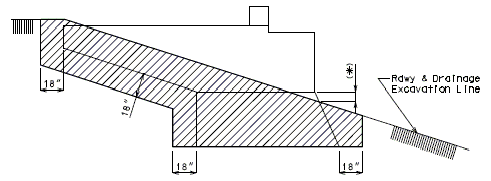
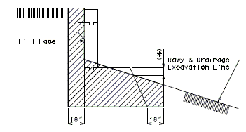
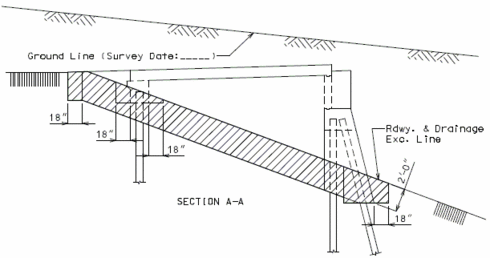
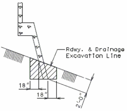
Excavation shall be computed in accordance with Sec 206 and the limits shown in this section.
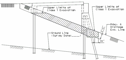
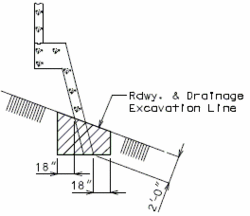
The Roadway and Drainage Excavation Line is the finish grade line after the bridge is completed in place. This may or may not correspond to the preliminary embankment line placed before the bridge is built.
The Excavation Datum is located at one foot above Low Water Elevation of the stream bed (round up to the next one foot). Use the low point of the streambed cross-section as Low Water Elevation, if a Low Water Elevation can not be found. Everything above this datum is Class 1 Excavation while everything below it is Class 2 Excavation.
Excavation Limit Rules
Soil or other sub-strata shall be excavated to the limits of:
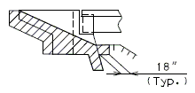
- 18” around the perimeter at the bottom of footings, and vertically (*) to the finished Roadway and Drainage Excavation Line
- 18” for tapered wings only and around the wings on end bents
- No excavation below sidewalls or wings of a semi-deep abutment
- The perimeter of seal courses
- No excavation shall be figured for piles or bracing
- If there is less than 10 cubic yards of total excavation, no excavation item needs to be listed in the Estimated Quantities. See EPG 751.50 Standard Detailing Notes for the appropriate notes.
Classes of Excavation (**)
Class 1, Class 2 Excavations shall be computed in accordance with Sec 206 and the limits shown in the figures below. Excavation for structures below Excavation Datum Elevation will be paid for as Class 2 Excavation. Excavation for structures above Excavation Datum Elevation will be paid for as Class 1 Excavation. Use a minimum of 10 cubic yards of Class 1 Excavation when there is Class 2.
Class 4 Excavation shall be used for culverts. Class 4 Excavation shall be computed in accordance with Sec 206 and the limits shown below. Culvert concrete removal for extensions will be paid for as Partial Removal of Culvert-Bridge Concrete. See the Design Layout for special cases.
Cases of Excavation
Case 1 is when the ground line survey is a higher elevation than the roadway and drainage excavation line.
Case 2 is when the ground line survey is a lower elevation than the roadway and drainage excavation line.
(*) Soil shall be excavated vertically from the bottom of the footing for footing on pile, 6” above the bottom of the footing for footing on rock and 18” above the bottom of the footing for footing on shale.
(**) Use Excavation in Rock if it is anticipated to be more than 10 cu. yard. The designer should check with the Structural Project Manager before calculating the quantity of Excavation in Rock. See EPG 751.6.1 Index of Quantities Bridge.
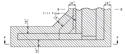
PART PLAN
SECTION A-A
SECTION B-B
(*) 12" at lowest beam depth for Girder Bridges and 24" for Concrete Slab Bridges.
Non-Integral End Bent Excavation Limits (Case I)
(**) Case 1 is when the ground line survey is a higher elevation than the roadway and drainage excavation line.
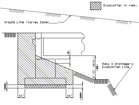
(*) 12" at lowest beam depth for Girder Bridges and 24" for Concrete Slab Bridges.
(**) Specify berm elevation or 4'-0" minimum clearance.
(***) 6" for footing on rock, 18" for footing on shale.
When calculating rock excavations allow 18" around and 6" underneath wing.
Use the following note on plans:
Note: Bottom of wings at End Bents No. __ and __ shall not be cast on rock.
Stub Bent Excavation Limits (Case I ****)
(****) Case 1 is when the ground line survey is a higher elevation than the roadway and drainage excavation line.
PART PLAN
SECTION A-A
SECTION B-B
Semi-Deep Abutment Excavation Limits (Case 1 *)
(*) Case 1 is when the ground line survey is a higher elevation than the roadway and drainage excavation line.
PLAN
SECTION A-A
SECTION B-B
Semi-Deep Abutment Excavation Limits (Case 2 *)
(*) Case 2 is when the ground line survey is a lower elevation than the roadway and drainage excavation line.
Excavation Limits: All Grade Seperations
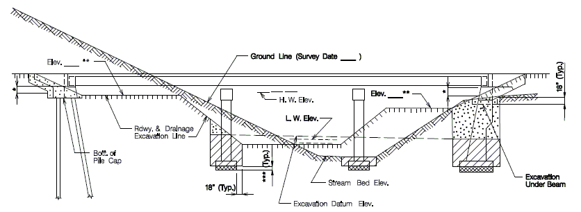
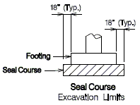
(*) 12" at lowest beam depth for Girder Bridges and 24" for Concrete Slab Bridges.
(**) BERM: Give the Elevation specified on DESIGN LAYOUT. If the berm elevation is not specified,
- show 4'-0" MINIMUM from bottom of superstructure to finished ground line.
(***) 0" for footing on Pile, 6" for footing on Rock, 18" for footing on Shale.
EXCAVATION DATUM: (Design Layout)
- (1) Indicate Low Water Elevation as given on Bridge Survey Report.
- (2) Indicate Stream Bed Elevation (Low point of stream bed).
(*) 12" at lowest beam depth for Girder Bridges and 24" for Concrete Slab Bridges.
Excavation Limits: Stream Crossing (No Excavation Item)
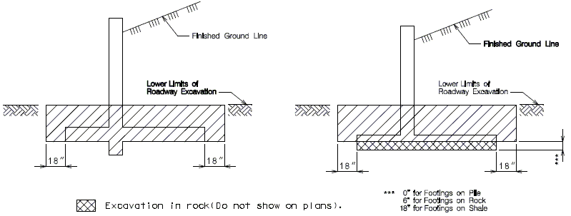
Note:
- Excavation to be included in Estimated Quantity Table (Class 1 or Class 4 Excavation for small block MSE walls,
- shall be calculated to the nearest 5 cubic yards).
- Final limits of the roadway and bridge excavation to be coordinated with the bridge plans prior to estimating.
- See EPG 751.50 Standard Detailing Notes for the appropriate notes.

Excavation to be included in Estimated Quantity Table (Class 4 Excavation shall be carried to the nearest 5 cubic yards). Final limits of the roadway and bridge excavation to be coordinated with the bridge plans prior to estimating.
Excavation of 18" adjacent to the removal of culvert ends for purpose of extending the culvert will not be considered excavation and is considered part of removal. (Refer to Sec 206)
See EPG 751.50 Standard Detailing Notes for the appropriate notes.
