751.39 Pile Footings: Difference between revisions
m attached article to new EPG 751 |
m Bridge has updated this article to show the correct design method (previous method was incorrect). |
||
| Line 1: | Line 1: | ||
[[Image:751.39 seal course.gif|right|thumb|800px|<center>Note: All pile shall be vertical. </center>]] | |||
===General Requirements=== | |||
Water elevation is to be determined for the site conditions by the preliminary design section; generally, less than the average of high and low water. | |||
Determine the uplift force per pile by deducting the weight of the seal course and friction between seal course and sheet piling of cofferdam from the uplift force produced by the hydrostatic head "h". | |||
Allowable uplift force per pile shall be determined by minimum of: | Use a friction value between the seal course and the sheet piling of 2 lbs./in<sup>2</sup> acting on (perimeter x depth) of seal course. | ||
===Pile Pull-out Force=== | |||
Allowable uplift force per pile shall be determined by the minimum of: | |||
:(1) The allowable friction capacity of pile = skin friction capacity of pile divided by a safety factor of 3.5. Use "DRIVEN" program to calculate skin friction capacity of pile (without end bearing or tip capacity). (See AASHTO Table 4.5.6.2A.) | |||
:(2) Allowable pull-out capacity of pile due to shear cone failure equal to ultimate pull-out capacity of pile due to shear failure (with maximum shear stress of <math>2\sqrt{f'c}</math> ) divided by a safety factor of 3. See Figs. 751.39.1, 751.39.2 and the following example. (See AASHTO 8.16.6.2.) | |||
:(3) Allowable Maximum pull-out capacity = 0.25 * Yield strength of steel * steel area of pile. (See AASHTO 4.5.7.3.) | |||
Note: Since CIP pile is not filled at this stage, use steel pipe pile area without concrete to determine the allowable maximum pull-out capacity. | |||
{| style="margin: 1em auto 1em auto" | |||
|- | |||
|colspan="2"|[[image:751.39.1.jpg|center|550px]] | |||
|- | |||
|colspan="2"|[[image:751.39.2.jpg|center|650px]] | |||
|- | |||
!align="center"|'''For Cast-in-Place Pile||align="2"|For H Pile | |||
|- | |||
|align="center"|Surface Area = ''πS(r + R)''||align="center"|Surface Area = ''(2a + 2b+ πR)S'' | |||
|- | |||
!colspan="2" align="center|Fig. 751.39.1, Full Shear Cone Failure Surface | |||
|} | |||
{| style="margin: 1em auto 1em auto" | |||
|- | |||
|colspan="2"|[[image:751.39.3.jpg|center|650px]] | |||
|- | |||
|colspan="2"|[[image:751.39.4.jpg|center|650px]] | |||
|- | |||
!align="center"|'''For Cast-in-Place Pile||align="2"|For H Pile | |||
|- | |- | ||
| | |align="center"|Reduced Surface Area = ''πS(r + R)''||align="center"|Reduced Surface Area = ''(2a + 2b+ πR)S'' | ||
|- | |- | ||
| | !colspan="2" align="center|Fig. 751.39.2, Reduced Shear Cone Failure Surface | ||
|} | |||
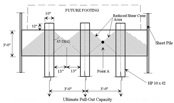
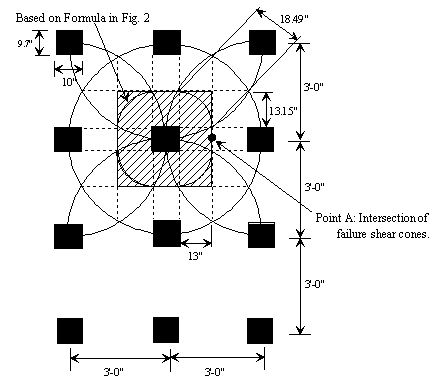
The reduced surface area defined in Fig. 751.39.2 is a conservative value compared to the actual reduced surface area. The geometry of the actual surface area is time consuming and complicated to compute, so a standard shape was chosen to ensure efficient use of the designer's time. | |||
===Example, Seal Course=== | |||
====Problem==== | |||
Check if Seal Course design is adequate. | |||
'''Given ''' | |||
:* Concrete Strength f'c= 3000 psi | |||
:* Pile spacing = 3'-0" | |||
:* 12 - HP 10 x 42 piles | |||
:* Area of an individual HP 10 x 42 Pile = A = 12.4 in<sup>2</sup> | |||
:* Yield strength of steel F<sub>y</sub> = 36 ksi | |||
:* Maximum axial load P<sub>y</sub> = F<sub>y</sub> (A) = 36 ksi (12.4 in<sup>2</sup>) = 446.4 kips | |||
:* Hydrostatic head h = 19' | |||
:* Seal Course = 12' x 15' x 3' | |||
:* Pile embedment below seal course = 15' | |||
[[image:751.39.5.jpg|center|700px|thumb|<center>'''Fig. 751.39.3, Seal Course Elevation'''</center>]] | |||
[[image:751.39.6.jpg|center|700px|thumb|<center>'''Fig. 751.39.4, Typical Shear Cone Failure Area</center>]] | |||
[[image:751.39.7.jpg|center|700px|thumb|<center>'''Fig. 751.39.5, Shear Failure Area for Individual Pile</center>]] | |||
====Solution==== | |||
'''Actual Uplift Force:''' | |||
{| style="margin: 1em auto 1em auto" align=left | |||
|- | |- | ||
| | |align=left|Uplift force of water = 12'(15')(19')(0.0624 kips/ft<sup>3</sup>) ||= 214 kips | ||
|- | |- | ||
| | |align=left|Weight of seal course = 12'(15')(3')(0.15 kips/ft<sup>3</sup>)||= -81 kips | ||
|- | |- | ||
| | |align=left|Friction of sheet pile = (15'+12')(2)(3')(144)(0.002kips/in<sup>2</sup>)||= <u>-47 kips</u> | ||
|- | |- | ||
| | |align=left|Net uplift of piles ||= 86 kips | ||
|- | |- | ||
| | |colspan="2" align=left|Actual uplift per pile = 86 kips/12 piles = 7.17 kips/pile | ||
|} | |} | ||
'''Allowable Uplift Force:''' | |||
Use the minimum of: | |||
(1) Allowable friction capacity of pile: | |||
: Using "DRIVEN" program, the skin friction capacity of pile is 53.97 kips. | |||
: Allowable friction capacity = 53.97 kips/3.5 = 15.42 kips | |||
(2) Allowable pull-out capacity of pile due to shear cone failure: | |||
: (Reference Figs. 751.39.4 and 751.39.5) | |||
::* Total Reduced Shear Cone Area for H-pile | |||
:::= ''(2a + 2b + πR)S'' | |||
:::= (2 x 9.7" + 2 x 10" + 3.1416 x 13") x 18.38" | |||
:::= 1474 in<sup>2</sup> | |||
::* Ultimate Shear Strength | |||
:::= <math>2 \sqrt{f'c} </math> | |||
:::= <math>2 \sqrt{3000}</math> | |||
:::= 109.5 psi | |||
::* Total Pull-Out Capacity | |||
:::= ''(Total Shear Cone Area) x (Ultimate Shear Strength) '' | |||
:::= 1474 in<sup>2</sup> x 0.1095 ksi = 161.4 kips ≤ P<sub>y</sub> = 446.4 kips | |||
::* Allowable Pull-Out Capacity | |||
:::= ''Total Pull-Out Capacity / Factor of Safety'' | |||
:::= 161.4 kips/3 = 53.8 kips | |||
(3) Allowable Maximum Pull-Out Capacity | |||
:='' 0.25 x F<sub>y</sub> x steel area of pile'' | |||
:= 0.25 x 36 x 12.4 | |||
:=111.6 kips | |||
Minimum from (1), (2) & (3): | |||
:Allowable uplift force = 15.42 kips | |||
:Actual uplift force = 7.17 kips | |||
::15.42 kips > 7.17 kips O.K. | |||
:Try seal course depth = 2'-6" | |||
'''Actual Uplift Force: ''' | |||
{| style="margin: 1em auto 1em auto" align=left | |||
|- | |||
|align=left|Uplift force of water||= 12'(15')(18.5')(0.0624 kips/ft<sup>3</sup>) = 207.8 kips | |||
|- | |||
|Weight of seal course ||= 12'(15')(2.5')(0.15 kips/ft<sup>3</sup>) = -67.5 kips | |||
|- | |||
|Friction of sheet pile ||= (15'+12')(2)(2.5')(144)(0.002 kips/in<sup>2</sup>) = -38.9 kips | |||
|- | |||
|Net uplift of piles ||= 101.4 kips | |||
|- | |||
|Actual uplift per pile ||= 101.4 kips/12 piles = 8.45 kips/pile | |||
|} | |||
'''Allowable Uplift Force:''' | |||
Use the minimum of: | |||
(1) Allowable friction capacity of pile: Using "DRIVEN" program, the skin friction capacity of pile is 54.37 kips. Allowable friction capacity 54.37 kips/3.5 = 15.53 kips | |||
(2) Allowable pull-out capacity of pile due to shear cone failure = 53.8 kips | |||
(3) Allowable maximum pull-out capacity = 111.6 kips | |||
Minimum from (1), (2) & (3): | |||
:Allowable uplift force = 15.53 kips | |||
:Actual uplift force = 8.45 kips | |||
::15.53 kips > 8.45 kips | |||
:(Thus, using a depth of 2'-6" is an economical design.) | |||
[[Category:751 LRFD Bridge Design Guidelines]] | [[Category:751 LRFD Bridge Design Guidelines]] | ||
Revision as of 13:10, 29 April 2011
General Requirements
Water elevation is to be determined for the site conditions by the preliminary design section; generally, less than the average of high and low water.
Determine the uplift force per pile by deducting the weight of the seal course and friction between seal course and sheet piling of cofferdam from the uplift force produced by the hydrostatic head "h".
Use a friction value between the seal course and the sheet piling of 2 lbs./in2 acting on (perimeter x depth) of seal course.
Pile Pull-out Force
Allowable uplift force per pile shall be determined by the minimum of:
- (1) The allowable friction capacity of pile = skin friction capacity of pile divided by a safety factor of 3.5. Use "DRIVEN" program to calculate skin friction capacity of pile (without end bearing or tip capacity). (See AASHTO Table 4.5.6.2A.)
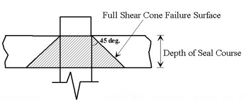
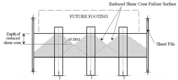
- (2) Allowable pull-out capacity of pile due to shear cone failure equal to ultimate pull-out capacity of pile due to shear failure (with maximum shear stress of ) divided by a safety factor of 3. See Figs. 751.39.1, 751.39.2 and the following example. (See AASHTO 8.16.6.2.)
- (3) Allowable Maximum pull-out capacity = 0.25 * Yield strength of steel * steel area of pile. (See AASHTO 4.5.7.3.)
Note: Since CIP pile is not filled at this stage, use steel pipe pile area without concrete to determine the allowable maximum pull-out capacity.
 | |
 | |
| For Cast-in-Place Pile | For H Pile |
|---|---|
| Surface Area = πS(r + R) | Surface Area = (2a + 2b+ πR)S |
| Fig. 751.39.1, Full Shear Cone Failure Surface | |
 | |
 | |
| For Cast-in-Place Pile | For H Pile |
|---|---|
| Reduced Surface Area = πS(r + R) | Reduced Surface Area = (2a + 2b+ πR)S |
| Fig. 751.39.2, Reduced Shear Cone Failure Surface | |
The reduced surface area defined in Fig. 751.39.2 is a conservative value compared to the actual reduced surface area. The geometry of the actual surface area is time consuming and complicated to compute, so a standard shape was chosen to ensure efficient use of the designer's time.
Example, Seal Course
Problem
Check if Seal Course design is adequate.
Given
- Concrete Strength f'c= 3000 psi
- Pile spacing = 3'-0"
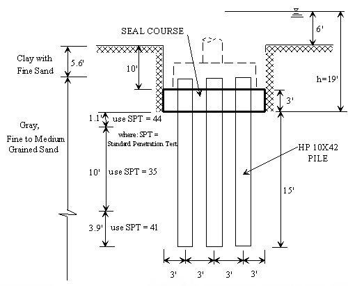
- 12 - HP 10 x 42 piles
- Area of an individual HP 10 x 42 Pile = A = 12.4 in2
- Yield strength of steel Fy = 36 ksi
- Maximum axial load Py = Fy (A) = 36 ksi (12.4 in2) = 446.4 kips
- Hydrostatic head h = 19'
- Seal Course = 12' x 15' x 3'
- Pile embedment below seal course = 15'
Solution
Actual Uplift Force:
| Uplift force of water = 12'(15')(19')(0.0624 kips/ft3) | = 214 kips |
| Weight of seal course = 12'(15')(3')(0.15 kips/ft3) | = -81 kips |
| Friction of sheet pile = (15'+12')(2)(3')(144)(0.002kips/in2) | = -47 kips |
| Net uplift of piles | = 86 kips |
| Actual uplift per pile = 86 kips/12 piles = 7.17 kips/pile | |
Allowable Uplift Force:
Use the minimum of:
(1) Allowable friction capacity of pile:
- Using "DRIVEN" program, the skin friction capacity of pile is 53.97 kips.
- Allowable friction capacity = 53.97 kips/3.5 = 15.42 kips
(2) Allowable pull-out capacity of pile due to shear cone failure:
- (Reference Figs. 751.39.4 and 751.39.5)
- Total Reduced Shear Cone Area for H-pile
- = (2a + 2b + πR)S
- = (2 x 9.7" + 2 x 10" + 3.1416 x 13") x 18.38"
- = 1474 in2
- Ultimate Shear Strength
- =
- =
- = 109.5 psi
- Total Pull-Out Capacity
- = (Total Shear Cone Area) x (Ultimate Shear Strength)
- = 1474 in2 x 0.1095 ksi = 161.4 kips ≤ Py = 446.4 kips
- Allowable Pull-Out Capacity
- = Total Pull-Out Capacity / Factor of Safety
- = 161.4 kips/3 = 53.8 kips
(3) Allowable Maximum Pull-Out Capacity
- = 0.25 x Fy x steel area of pile
- = 0.25 x 36 x 12.4
- =111.6 kips
Minimum from (1), (2) & (3):
- Allowable uplift force = 15.42 kips
- Actual uplift force = 7.17 kips
- 15.42 kips > 7.17 kips O.K.
- Try seal course depth = 2'-6"
Actual Uplift Force:
| Uplift force of water | = 12'(15')(18.5')(0.0624 kips/ft3) = 207.8 kips |
| Weight of seal course | = 12'(15')(2.5')(0.15 kips/ft3) = -67.5 kips |
| Friction of sheet pile | = (15'+12')(2)(2.5')(144)(0.002 kips/in2) = -38.9 kips |
| Net uplift of piles | = 101.4 kips |
| Actual uplift per pile | = 101.4 kips/12 piles = 8.45 kips/pile |
Allowable Uplift Force:
Use the minimum of:
(1) Allowable friction capacity of pile: Using "DRIVEN" program, the skin friction capacity of pile is 54.37 kips. Allowable friction capacity 54.37 kips/3.5 = 15.53 kips
(2) Allowable pull-out capacity of pile due to shear cone failure = 53.8 kips
(3) Allowable maximum pull-out capacity = 111.6 kips
Minimum from (1), (2) & (3):
- Allowable uplift force = 15.53 kips
- Actual uplift force = 8.45 kips
- 15.53 kips > 8.45 kips
- (Thus, using a depth of 2'-6" is an economical design.)