905.1 Traffic Data Collection: Difference between revisions
m renumbered article |
m →905.1.2.2 Speed Study: updated link to EPG 949.2 |
||
| Line 95: | Line 95: | ||
===905.1.2.2 Speed Study=== | ===905.1.2.2 Speed Study=== | ||
A speed study is performed to determine the [[949.2 | A speed study is performed to determine the [[949.2 Speed Limit Guidelines|prevailing speed]] at a location. The prevailing speed is used to determine if the speed limit is set appropriately and to check for proper sight distances along the roadway. | ||
===905.1.2.3 Traffic Flow=== | ===905.1.2.3 Traffic Flow=== | ||
Revision as of 15:43, 11 February 2010

To perform a traffic study, certain data should be collected. A good source of data can be obtained from MoDOT’s Transportation Management System (TMS). TMS has inventories for roadway information as well as crash information. For some traffic studies, data from TMS may be enough. For other studies, field data will be required. The Traffic Data Collection article will show data available from TMS and data required from the field.
| Transportation Management Systems, Assessment |
| Summary 2004 |
| Report 2004 |
| See also: Innovation Library |
905.1.1 Transportation Management System (TMS)
905.1.1.1 Accident Summary
The Accident Summary TMS application ties roadway data to crash data. An example of the Accident Summary application may look like the following:
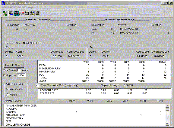
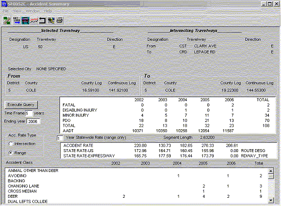
From the application, the following information can be found:
- Crashes by severity
- AADT
- Accident rate (intersection or range)
- State Accident Rate (by route designation & by roadway type)
- Accident Class
The Accident Summary application provides a quick review of crash severity, comparative crash rates, and accidents by classification.
For range studies, accident rates calculated by TMS is frequency based, determined by the total number of crashes per 100 million vehicle miles traveled. Below is the equation used to calculate range crash rates:
Range lengths of more than one mile should be used in the calculation, if practical. As seen in the rate calculation, an accident rate for a route less than one mile long will result in an artificially high crash rate.
For intersection studies, accident rates calculated by TMS are also frequency-based but are determined by the total number of crashes by 1 million entering vehicles. Below is the equation used to calculate intersection crash rates:
Crash rates are a good indication of the level of operation for an intersection. It is not easy to determine if an individual crash rate is good or bad by itself. For this reason, there is a State Rate available for comparison. For range studies, the Accident Summary application compares the selected route to statewide routes of similar route designations (IS, US, MO, RT, etc.) and route type (freeway, expressway, two-lane, etc.). For intersection studies, a similar concept is in place to compare intersection with similar geometric design and entering volumes. Due to roadway data constraints at this time, not all intersections are comparable to statewide rates.
Additional information available through Accident Summary is the Accident Class, Statewide Average Accident Rates and ARAN video. The Accident Class field provides a general description of the crash; i.e. rear-end, head-on, left turn, etc. The Statewide Average Accident Rate application can be launched to see more in depth review of available accident rates. The ARAN video is available for most routes that allow the user to view the road as driven by the ARAN van.
905.1.1.2 Accident Browser
The Accident Browser application can be launched from the Accident Summary application or from the TMS menu. An example of the Accident Summary application may look like the following:
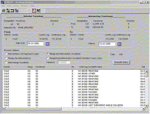
From the application, the following information can be found:
- Accident location
- Accident classification
- Accident date
- Accident severity
- Accident image number
- Accident relation to roadway (range/intersection/interchange)
- Light condition
- Road surface condition
- Weather condition
This information can be used to determine when crashes are occurring and the best times to go to the field to collect data and observe traffic conditions. Additionally, the collision diagram software and ARAN video can be launched from the Accident Browser application.
905.1.1.3 Statewide Average Accident Rates
The Statewide Average Accident Rates application can be launched from the TMS Menu or Accident Summary application. The application allows the user to view crash rates by state, district or county for many combinations of crash severity and roadway information. The Statewide Average Accident Rates are used to determine if the studied range is above or below the statewide average.
905.1.1.4 Intersection Expected Accident Rates
The Intersection Expected Accident Rates application can be launched from the TMS Menu. The application allows the user to compare the intersection being studied with other intersections in the state with similar roadway and traffic characteristics.
905.1.1.5 Queries & Reports
Queries & Reports are located under the TMS menu. Within the Queries & Reports menu are applications that will provide pavement reports, safety reports, state of the system (SOS) reports and traffic reports. The safety reports include the Accident Statistics Manual, High Severity Lists and various other accident reports by severity. The SOS reports provide roadway inventory information. The traffic reports provide AADT information for all state routes.
905.1.1.6 ArcMAP Queries
ArcMAP allows the user to map roadway and traffic data. Queries are available within the ArcMAP tool to map basic information. The software allows users to perform database queries from other query applications and import the data into ArcMAP for viewing. This mapping tool is useful for displaying data for public meetings.
905.1.1.7 Direct access to TMS Databases
TMS users have direct access to the TMS databases. Linking databases by using software such as Microsoft Access, allows TMS users to query data in a specialized manner. While the applications in TMS allow for most combinations of data, the applications cannot account for every scenario. When such a scenario occurs, specialized queries must be used.
905.1.2 Non-TMS Field Data
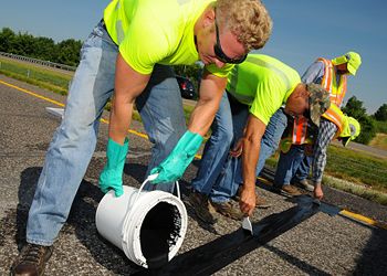
While some field data may be available in TMS, it is often useful to obtain current data from the field. The TMS applications are data intensive. Very few state routes are counted every year. Traffic patterns can change quickly with new developments. For these reasons, it is encouraged to obtain field data for traffic studies.
905.1.2.1 Traffic Counts
As mentioned, traffic patterns can change quickly. There are several ways to review traffic data that may be important to the study. For intersections, it is not uncommon to perform a 12-hour turning movement count. When counting an intersection for 12 hours, track the turning movements by 15-minute intervals. By tracking vehicle actions using 15-minute intervals, the intersection can be reviewed for peak hour(s) movements and assist in signal timing plans.
When the traffic study involves a range location, count cards can be placed to gather AADT and sometimes speed. Due to new developments and the TMS count cycle, it may be a couple years before a road is counted. It is also good to confirm the information in TMS. While in the field gathering traffic counts, it is a good idea to perform a spot speed study as well.
905.1.2.2 Speed Study
A speed study is performed to determine the prevailing speed at a location. The prevailing speed is used to determine if the speed limit is set appropriately and to check for proper sight distances along the roadway.
905.1.2.3 Traffic Flow
While performing a traffic study for either an intersection or range, take notes about the traffic flow. Look for erratic and illegal maneuvers or other operational problems, as these may indicate signing needs or other operational deficiencies.
905.1.2.4 Condition Diagram
As mentioned in the HAL Manual, the Condition Diagram is a drawing (to scale, if practical), of the existing roadway, control device locations and major features in the nearby environment.
905.1.2.5 Sight Distance Measurements
Sight Distances should be measured for at-grade intersections and ranges. There are four basic sight distance measurements that will be obtained:
- Stopping Sight Distance
- Entering Sight Distance
- Decision Sight Distance and
- Passing Sight Distance.
Sight distances will be measured for
If sight distance is being reviewed due to an entrance permit, refer to 941.19 Sight Distance for Driveways.
905.1.2.6 Measuring Degree of Curvature
Sometimes horizontal degrees of curvature are used to make engineering decisions. An example is the article on chevron placement. By using equations involving the curve’s radius, LC (length of chord), degree of curve, and middle ordinate, a relationship can be calculated. The relationship assumes a chord length of 62 ft. By using a chord length of 62 ft., the middle ordinate (measured in inches) equals the degree of curvature, thus a simple field check using a 62 ft. length of rope can be used to measure the degree of curvature.
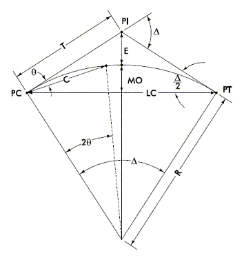
Where,
- PI = points of intersection of back tangent and forward tangent
- PC = point of curvature, the point of change from back tangent to circular curve
- PT = point of tangency, the point of change from circular curve to forward tangent
- LC = Total chord length, or long chord, from PC to PT in ft. for the circular curve
- D = Degree of curvature, the central angle that subtends a 100 ft. arc. The degree of curvature is determined by the appropriate design speed (anticipated posted speed).
- = Total intersection (or delta) angle between back and forward tangents
- T = Tangent distance in ft. The distance between the PC and PI or the PI and PT.
- L = Total length in ft. of the circular curve from PC to PT measured along its arc.
- E = External distance (radial distance) in ft. from PI to the midpoint of the circular curve.
Table 905.1.2.6
| Assume “LC” | Degree of Curve (D) | Convert Degrees to Radians | Calculate “R”, sin(1/2D)=50/R | Calculate , LC = 2R sin (/2) | Calculate “MO” in ft., MO = R(1 – cos (/2)) | ”MO”, in inches |
|---|---|---|---|---|---|---|
| 62 | 1 | 0.017453293 | 5729.650674 | 0.010820957 | 0.08 | 1.01 |
| 62 | 2 | 0.034906585 | 2864.934425 | 0.021641406 | 0.17 | 2.01 |
| 62 | 3 | 0.052359878 | 1910.077501 | 0.032460841 | 0.25 | 3.02 |
| 62 | 4 | 0.06981317 | 1432.685417 | 0.043278753 | 0.34 | 4.03 |
| 62 | 5 | 0.087266463 | 1146.279281 | 0.054094636 | 0.42 | 5.03 |
| 62 | 6 | 0.104719755 | 955.3661305 | 0.064907979 | 0.50 | 6.04 |
| 62 | 7 | 0.122173048 | 819.020412 | 0.075718276 | 0.59 | 7.04 |
| 62 | 8 | 0.13962634 | 716.7793513 | 0.086525016 | 0.67 | 8.05 |
| 62 | 9 | 0.157079633 | 637.2747422 | 0.097327689 | 0.75 | 9.05 |