751.13 Expansion Joint Systems: Difference between revisions
m First detail shown on the EPG "Steel Structure Details at Intermediate Bent" was for an End Bent - put in correct figure. |
m attached article to new EPG 751 |
||
| Line 1,383: | Line 1,383: | ||
[[Category:751 LRFD | [[Category:751 LRFD Bridge Design Guidelines]] | ||
Revision as of 08:24, 15 April 2010
751.13.1 Expansion Devices
751.13.1.1 General
The number of movable deck joints in a structure should be minimized. Deck joints should be avoided over roadways, railroads, sidewalks, other public areas, and at the low point of sag vertical curves.
Consult the Structural Project Manager, if the use of special covering floor plates in shoulder areas should be considered.
If no expansion device is specified in the Design Layout, but due to the length of structure an expansion device is required, consult the Structural Project Manager for the type to be used. The roadway surface gap, W, (Except Flat and Finger Plates) in a transverse deck joint, measured in the direction of travel shall satisfy:
For single gaps:
- 1" ≤ W ≤ 4"
| EXPANSION JOINT SELECTION | ||
|---|---|---|
| Allowable Movement | Allowable Skew | |
| Silicone Expansion Joint Sealant | 0 – 2” | ≤ 20˚ |
| Preformed Compression Joint Seal | 0 – 2” | ≤ 20˚ |
| Strip Seals | 2” to 4” | ≤ 45˚ |
| Flat Plate | > 45˚ | |
| Finger Plate | ||
Movement Calculation (in the direction of travel)
= Load factor for temperature movement
Coefficients, ()
| Steel: | Thermal - 0.0000065 ft/ft/F° |
| Concrete: | Thermal - 0.0000060 ft/ft/F° |
Temperature Range From 60°F, ()
Temperature Range is based on a design installation temperature of 60°F.
| Rise | Fall | Range | |
|---|---|---|---|
| Steel Structures | 60°F | 90°F | 150°F
(From -30° to 120°) |
| Concrete Structures | 50°F | 70°F | 120°F
(From -10° to 110°) |
Actual Expansion Length, (L)
When Expansion joints are used for long span structures with deep girders, movement calculations should also consider the bearings and possible resulting girder rotation.
Installation Width
The installation width, gap, should be adjusted for temperatures above or below the design installation temperature. Movement for a 10°F change in temperature should be indicated on the plans to the nearest 1/16” by using the appropriate note.
Movement for 10°F change in temperature = (α)(10°F)(L)(Cos θ)
751.13.1.2 Expansion and Contraction Length
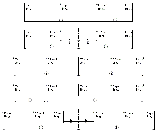
Note:
![]() = Expansion and contraction length.
= Expansion and contraction length.
For configurations not shown, a temperature force distribution analysis may be necessary to estimate the point of thermal origin.
751.13.1.3 Expansion Device on Skewed Curved Structures
Expansion Device on Skewed Curved Structures
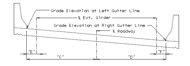
Add the “Section Thru Centerline Expansion Gap” and the Table shown below to the Expansion Device sheet for skewed curved structures.
PART PLAN
SECTION THRU EXPANSION GAP
| BENT NO. | GRADE ELEVATION | ANGLE | HORIZONTAL DIMENSIONS | ||||||
| LEFT GUTTER LINE | RDWY. | RIGHT GUTTER LINE | |||||||
| "A" | "B" | "C" | "D" | "E" | "F" | ||||
751.13.1.4 Details of Substructure Protection
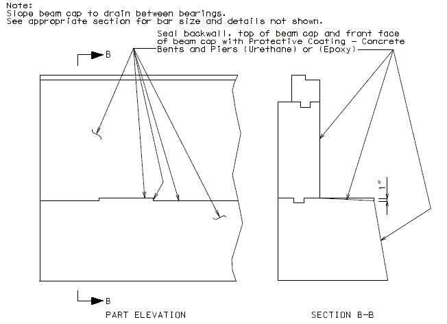
A protective coating shall be applied to concrete surfaces exposed to drainage from the roadway. Indicate surface to be coated on plans. Urethane resembles black tar which is used where aesthetics is not a concern, otherwise use epoxy.
751.13.2 Silicone Expansion Joint Sealant
751.13.2.1 General
Silicone Expansion Joint Sealant is an economical system and should be used for movements up to 2" with skews ≤20°.
This system is preferred by maintenance because it is easily replaced if necessary.
PART CROSS SECTION THRU EXPANSION JOINT
Minimum thickness of angle shall be 1/2".
751.13.2.2 Steel Structure Details at End Bents
SECTION THRU EXPANSION JOINT
PART PLAN
 |

|
| DETAIL "B" | DETAIL "A" |
751.13.2.3 Steel Structure Details at Intermediate Bents
SECTION B-B
PART PLAN
 |

|
| DETAIL "B" | DETAIL "A" |
751.13.2.4 Prestressed Structure Details at End Bents

| |
| SECTION B-B | |

| |
| PART PLAN | |
 |

|
| DETAIL "B" | DETAIL "A" |
751.13.2.5 Barrier Curb Details
SQUARE STRUCTURE
SKEWED STRUCTURE
(*) The working point is always placed on the front face side of backwall at the gutter line.
751.13.2.6 Safety Barrier Curb at End Bents
 |

|
| ELEVATION | PART SECTION A-A |
 |

|
| PART PLAN B-B | PART PLAN B-B |
| (SQUARE) | (SKEWED) |
751.13.2.7 Double Faced Median Barrier Bridge Curb
For details not shown of median barrier bridge curb, see the safety barrier curb details, Design Division Standard Drawings (Concrete Median Barrier) and Bridge Design Layout.

| |
| TYPICAL PART SECTION A-A | |
 |

|
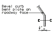
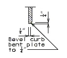
| PART ELEVATION AT END OF BEVELED CURB BENT PLATE | SECTION C-C |
 |

|
| PART ELEVATION OF BARRIER CURB | TYPICAL PART SECTION B-B |
751.13.2.8 Polymer Concrete
Silicone Expansion Joint Sealant may be used on rehabilitation projects where other expansion devices need to be replaced. Consult with Structural Project Manager about the use of polymer concrete with silicone sealant. Silicone sealant is to be designed with the same requirements as normal silicone expansion joint sealant.
Note: Anchorage system shall be welded to steel armor with apporpriate weld to meet AASHTO Fatigue Category C for connection.

DETAIL OF SINUSOIDAL BAR
Note: A pay item exists for this type of expansion device system.
The system will be paid for under Silicone Expansion Joint Sealant System per linear foot. Polymer Concrete will be paid for under Polymer Concrete per cubic foot.

DETAIL OF SHEAR CONNETOR
(#4 Reinforcing bar shall be bent in a similar manner)751.13.3 Preformed Compression Joint Seal
751.13.3.1 General
Performed Compression Seal Expansion Joint Systems is an alternate to Silicone Expansion Joint Sealant System. The system can be used for movements up to 2" with skews ≤ 20°. Future replacement of this system is more difficult than replacement of the Silicone Expansion Joint Sealant System.
PART CROSS SECTION THRU EXPANSION JOINT
Size of Armor Angle:
Vertical leg of angle shall be a minimum of  + 3/4", horizontal leg of angle shall be a minimum of 3". Minimum thickness of angle shall be 1/2".
Check 1" ≤ w ≤ 4" after select seal size, w = gap at top slab in the direction of travel, in inch.
751.13.3.2 Steel Structure Details

SECTION B-B
PART PLAN
 |

|
| DETAIL "B" | DETAIL "A" |
751.13.3.3 Prestressed Structure Details
SECTION B-B
PART PLAN
 |

|
| DETAIL "B" | DETAIL "A" |
751.13.3.4 Barrier Curb Details
 |

|
| PART SECTION B-B | PART SECTION A-A |
 |

|
| PART ELEVATION AT END | SECTION C-C
OF BEVELED CURB BENT PLATE |
 |

|
| PART ELEVATION OF BARRIER CURB | PART SECTION THRU SAFETY BARRIER CURB SHOWING PREFORMED COMPRESSION SEAL |
SQUARE STRUCTURE
SKEWED STRUCTURE
(*) The working point is always placed on the front face side of backwall at the gutter line.
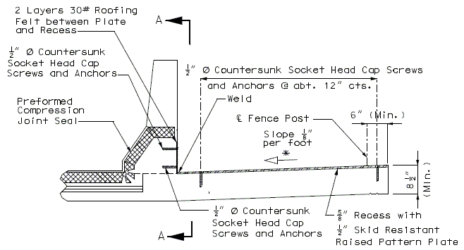
751.13.3.5 Sidewalk Details
PART SECTION THRU CENTER OF EXPANSION DEVICE
PART SECTION A-A
751.13.3.6 Double Faced Median Barrier Bridge Curb
TYPICAL PART SECTION A-A
 |

|
| PART ELEVATION AT END OF BEVELED CURB BENT PLATE | SECTION C-C |
 |

|
| PART ELEVATION OF BARRIER CURB | TYPICAL PART SECTION B-B |
751.13.4 Strip Seal Expansion Joint System
751.13.4.1 General
Strip Seal Expansion Joint Systems should be used for movements greater than 2” and less than 4” for skews < 45°. Use flat plate expansion devices on curved structures and skews over 45°.
The installation width, gap = 2”, based on a design installation temperature of 60°F.
On skewed bridges, the strip seal expansion devices must be checked for parallel and perpendicular movements. Parallel movements (Racking) shall be less than 1 ½” for either rise or fall movements. Maximum skew shall be 45°.
Formulas: M = 1.2(ΔT)(α)(L) : Bridge total movement or individual rise and fall movements
- ΔT = Corresponding temperature range
- L = Expansion length
- α = Coefficient of linear expansion
M = M cos θ : Movement perpendicular to joint
M = M sin θ : Movement parallel to joint
- θ = skew angle

Gland Size
| Strip Seal Gland Size | Gap at Top Slab (60°F) | Min. Joint Width ( to Joint) | Max. Joint Width ( to Joint) | Max. Gap ( Rdwy) |
| 3” | 2” | 1” | 3” | 4” |
| 4” | 2” | 1” | 4” | 4” |
751.13.4.2 Gland Extrusion Details
DETAIL OF JOINT ARMOR
DETAIL OF GLAND
751.13.4.3 Joint System Details (Steel Structures)
SECTION B-B
PART PLAN
DETAIL "A"
DETAIL "B"
(**) Dimension required to clear bearing stiffener (1 1/2" Min.). (Dimension to be shown on plans)
SECTION B-B
PART PLAN
DETAIL "A"
DETAIL "B"
(**) Dimension required to clear bearing stiffener (1 1/2" Min.). (Dimension to be shown on plans)
751.13.4.4 Joint System Details (Prestressed Structures)
(**) 3/4" Min. (Do not show on plans.)
SECTION B-B
PART PLAN
 |

|
| DETAIL "B" | DETAIL "A" |
(*) Dimension required along centerline of girder (Dimension to be shown on plans).
(**) 3/4" Min. (Do not show on plans.)
SECTION B-B
PART PLAN
 |

|
| DETAIL "B" | DETAIL "A" |
(*) Dimension required along centerline of girder (Dimension to be shown on plans).
751.13.4.5 Barrier Curb Details
 |

|
| PART SECTION B-B | PART SECTION A-A |
 |

|
| PART ELEVATION AT END OF BEVELED CURB BENT PLATE |
SECTION C-C |
PART ELEVATION OF BARRIER CURB
SECTION THRU JOINT
PART PLAN (SQUARE BRIDGE)
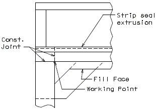
(*) Working Point is always at front face of backwall at gutterline.
PART PLAN (SKEWED BRIDGE)
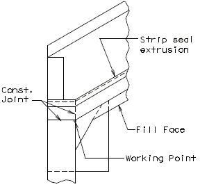
BARRIER CURB AT END BENTS
 |

|
| ELEVATION | PART SECTION A-A |
 |
|
| PART PLAN B-B (SQUARE) |
PART PLAN B-B (SKEWED) |
751.13.4.6 Double Faced Median Barrier Curb Details
Note: Do not use barrier curb plate on square structures.
For details not shown of median barrier bridge curb, see the safety barrier curb details, Design Division Standard Plans (Concrete Median Barrier) and Bridge Design Layout.
PART ELEVATION OF BARRIER CURB
751.13.4.7 Drainage Details
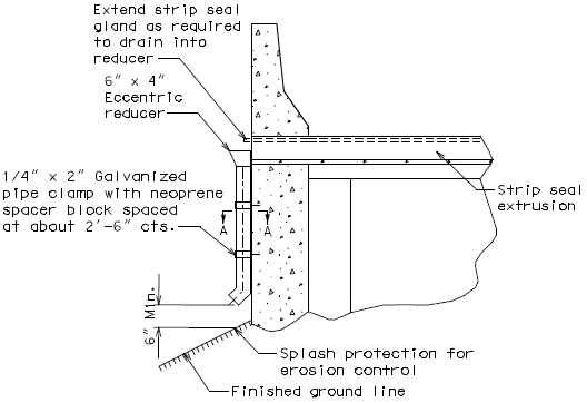
In order for strip seal expansion joint systems to function properly, the gland shall be allowed to drain to prevent build-up of debris. Debris may punch holes in the gland and the extra load may possibly pull the gland from the extrusions.
To prevent debris buildup on the strip seals the gland should not be turned up at the barrier curb. Instead, the steel armor with extrusions should be extended to the face of the slab through the barrier curb.
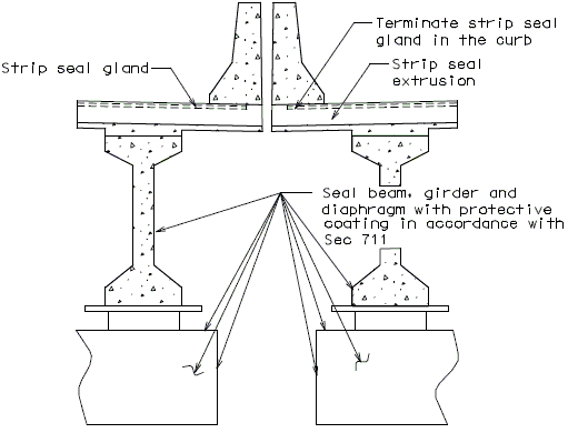
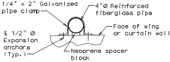
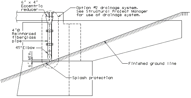
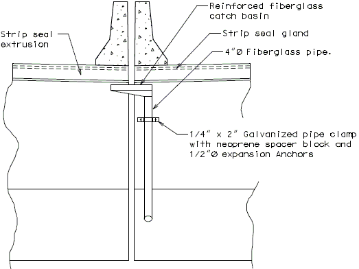
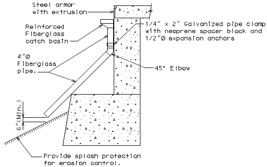
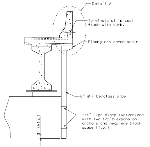
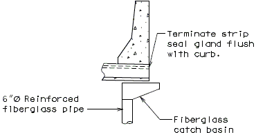
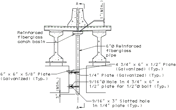
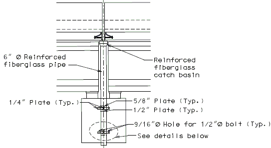
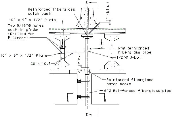
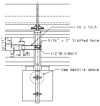
Drainage shall be handled by one of two methods. The first method is to let the water run off the gland and free fall to the ground below. The gland should extend past the edge of slab 3 inches minimum. At intermediate bents, the bent cap should have a protective coating applied to prevent moisture saturation of the concrete. On structures where there is an adjacent structure separated by a median barrier curb with an open joint (Type D or Split Median) the gland should be terminated at some point under the curb at all bent types and protective coating should be applied at all faces exposed to moisture. The second method of drainage is to provide a fiberglass pipe drainage system to collect water at the bents.
See the Structural Project Manager for the method of drainage to be used.
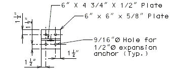
The following pages provide some possible details that may be used for strip seal expansion joint drainage systems.
If the fiberglass pipe drainage system is used, payment will be made under the pay item. Drainage System (On structure), Lump Sum.
Option #1- No Drainage System, at End Bent
Option #1- No Drainage Sytem, at Split Median Barrier Curb at Intermediate Bent
Option #2 - One-Piece Drain System at End Bent
FRONT ELEVATION
PART SECTION A-A
SIDE ELEVATION
Option #2 - One-Piece Drain System, Split Median Barrier Curb at End Bent
FRONT ELEVATION
SECTION THRU BENT
Option #2 - One-Piece Drain System, Intermediate Bent
DETAIL A
(Optional)
Option #2 - One-Piece Drain System at Split Median Barrier Curb at Intermediate Bent
SECTION THRU JOINT
Note: If dropping water to ground from bottom of beam is not allowed, an additional pipe system shall be used.
SECTION A-A
Option #3 - Three-Piece Drain System at Split Median Barrier Curb at Intermediate Bent
SECTION THRU JOINT
SECTION B-B
SECTION C-C
SECTION D-D
(*)Varies (Space holes to clear B1 bars in P/S girders. Use 6" for plate girders.)
SECTION E-E
751.13.4.8 Polymer Concrete
Strip Seal Expansion Joint System may be used on rehabilitation projects where other expansion devices need to be replaced. Consult with Structural Project Manager about the use of polymer concrete with strip seals. Strip seal is to be designed with the same requirements as a normal strip seal expansion joint system.
- Note: Anchorage system shall be welded to strip seal steel armor with appropriate weld to meet AASHTO Fatigue for connection.
- Note: A pay item exists for this type of expansion joint system. The system will be paid for under Strip Seal Expansion Joint System per linear foot. Polymer Concrete will be paid for under Polymer Cocrete per cubic foot.
DETAIL OF SHEAR CONNECTOR
(Alternate #4 reinforcing bar shall be bent similarly)751.13.5 Flat Plate Expansion Devices
751.13.5.1 General
Flat Plate Expansion Joint System should be used where Strip Seals and Preformed Compression Joints can not be used due to large expansion lengths or curved structures and skews over 45˚.
The installation width, gap = 3 1/2" is based on a design installation
temperature of 60˚F.
Flat Plate expansion devices can be used on any skewed bridges.
The max. surface gap, W ≤ 4" does not effect flat plate expansion devices
due to the fact there are no visible open joints.
751.13.5.2 Steel Structure Details
Dimensions shown are perpendicular to centerline of joint and do not vary with skew.
PART SECTION AT END BENT
PART SECTION AT INTERMEDIATE BENT
Note:
- Part longitudinal sections for bridges on grades or verticle curves having a plate type intermediate expansion device shall be detailed with the expansion plate anchor to the long span side. If equal spans, then place expansion plate anchor on the high side. For bevel plate and permissible field splice details, see this manual section.
751.13.5.3 Prestressed Structure Details
Dimensions shown are perpendicular to centerline of joint and do not vary with skew.
PART SECTION AT END BENT
PART SECTION AT INTERMEDIATE BENT
Notes:
- Part longitudinal sections for bridges on grades or vertical curves having a plate type intermediate expansion device shall be detailed with plate anchor to the long span. If equal spans, then place expansion plate anchor on the high side.
- (*) Spaced between prestress girder reinforcing bars.
751.13.5.4 Typical Part Plan Details
PART PLAN AT END BENT
PART PLAN AT INTERMEDIATE BENT
Note: Vent holes not shown for clarity.
PART PLAN AT END BENT
PART PLAN AT INTERMEDIATE BENT
Note: Vent holes not shown for clarity.
751.13.5.5 Typical Aligning Bolt and Bevel Plate Details
PART PLAN
SECTION A-A
(TYPICAL)
(*) 7/16" Ø Hole, countersunk in the roadway plate; with slotted hole 1/2" x 1" in the angle; and the bar 1 1/4" x 3/8" x 2" tapped for 3/8" Ø flat head stove bolt at about 4'-0" cts. Remove bolt after concrete has set. Offset vertical and horizontal concrete vent holes in 5/8" angle (Do not alternate)
 |

|
| PART SECTION (TYPICAL) |
TYPICAL BEVEL PLATE |
| Note: | Use the bevel plate (at end bents only) when the grade of the slab is 3.0% or more. |
| Modify the roadway plate, the 5/8" vertical plate and the continuous bar when the bevel plate is required. |
751.13.5.6 Typical Permissible Field Splice Details
PART PLAN
 |

|
| PART PLAN OF ANGLE AND BAR |
PART PLAN OF ROADWAY PLATE AND ⅝" PLATE |
Note:
If the expansion device length is over 60 feet, splicing is permissible. Details for a steel structure shown, prestress details are similar.
751.13.5.7 Plan of Beam at Bearings
(*) Note: Details for a steel structure shown, details for a prestress structure similar.
751.13.5.8 Barrier Curb Details
 |

|
| PART ELEVATION AT END OF BEVELED CURB BENT PLATE |
SECTION C-C |
 |

|
| ELEVATION OF BARRIER CURB | PART SECTION A-A |
751.13.5.9 Miscellaneous Details
TYPICAL SIDEWALK DETAILS
TYPICAL MEDIAN DETAILS
PART SECTION A-A
751.13.6 Finger Plate Expansion Devices
751.13.6.1 General
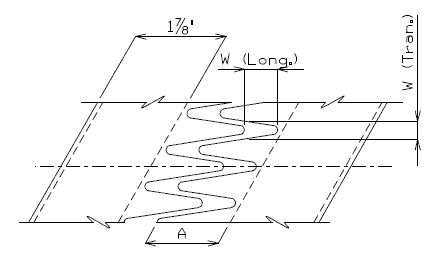
The max. roadway surface gap (W) shall meet the following criteria:
When W(Long.) < 8", Then W(Tran.) < 3".
OR
When W(Long.) > 8", Then W(Tran.) < 2".
The min. finger overlap = 1.5"
Expansion lengths are calculated from the total movement value by the following equation:
Expansion length =
Where:
For Concrete:
= 0.000006 ft/ft/˚F
= 120˚F
For Steel:
= 0.0000065 ft/ft/˚F
= 150˚F
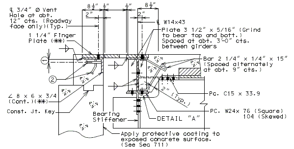
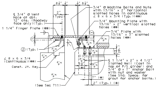
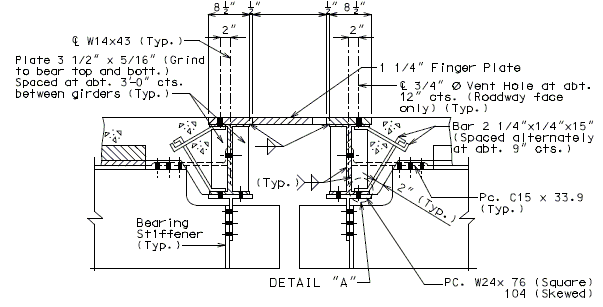
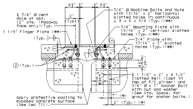
751.13.6.2 Details at Bents
Details at End Bent
Dimensions shown are perpendicular to centerline of joint and do not vary with skew (Unless otherwise noted).
PART SECTION THRU EXPANSION DEVICE
(Steel Structure)
 |

|
| DETAIL "A" |
PART SECTION THRU EXPANSION DEVICE
(Prestress Structure)
(*) Dimension along centerline of girder.
(**) When distance "A" or "D" shown in LRFD DG Sec. 6.3 is greater than 9" or 12", respectively, then the details of supporting anles, mounting plates, shear studs and finger plate thickness need to be specially designed. Mounting Plates shall not be less than supporting angle in thickness.
Details at Intermediate Bent
Dimensions shown are perpendicular to centerline of joint and do not vary with skew (Unless otherwise noted).
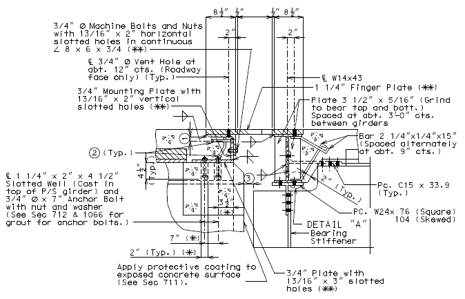
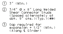
PART SECTION THRU EXPANSION DEVICE
(Steel Structure)
Note: for Details "A" see above.
PART SECTION THRU EXPANSION DEVICE
(Prestressed Structure)
(*) Dimension along centerline of Girder.
(**) When distance "A" or "D" shown in LRFD DG Sec 6.3 is greater than 9" or 12", respectively, then the details of supporting angles, mounting plates, shear studs and finger plate thickness need to be specially designed. Mounting Plates shall not be less than supporting angle in thickness.
Dimensions shown are perpendicular to centerline of joint and do not vary with skew (Unless otherwise noted).
(*) Dimension along centerline of Girder.
(**) When distance "A" or "D" shown below is greater than 9" or 12", respectively, then the details of supporting angles, mounting plates, shear studs and finger plate thickness need to be specially designed. Mounting Plates shall not be less than supporting angle in thickness.
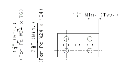
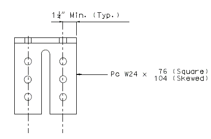
Details of W24 Piece
PLAN
| ELEVATION OF PIECE W24 X | 76 (SQUARED) |
| 104 (SKEWED) |
Note:
Place the above details near "Part Section Thru Expansion Joint System For Finger Plates".
All holes shown for connections to be subpunched 11/16" Ø (shop or field drill) and reamed to 13/16" Ø in field.
751.13.6.3 Typical Plan of Plate
 |
| ||||||||||||||||||||||||||||||
| TYPICAL PLAN OF PLATE (SQUARE) |
|||||||||||||||||||||||||||||||
 |
| ||||||||||||||||||||||||||||||
| TYPICAL PLAN OF PLATE (SKEWED) |
|||||||||||||||||||||||||||||||
Ø = skew angle
C = A - 0.5") + [(Gap @ 60°F) cos Ø]
D = (A- 0.5") sec Ø
E = 4" - B
751.13.6.4 Barrier Curb Details
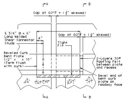 |
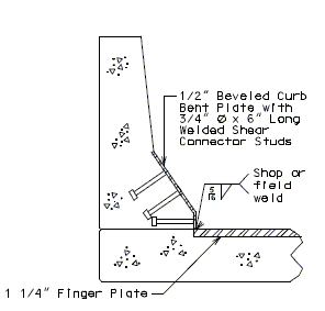
|
| PART ELEVATION OF BARRIER CURB (END BENT) |
TYPICAL PART SECTION A-A |
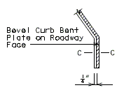 |
|
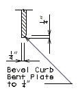
| PART ELEVATION AT END OF BEVELED CURB BENT PLATE |
SECTION C-C |
 |
|
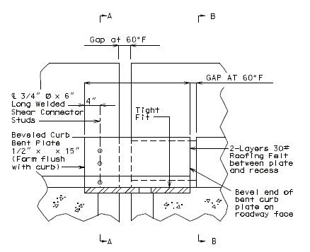
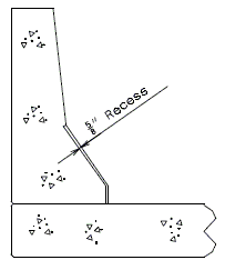
| PART ELEVATION OF BARRIER CURB (INTERMEDIATE BENT) |
TYPICAL PART SECTION B-B |
PART PLAN OF CURB AT END BENT (SQUARE)
PART PLAN OF CURB AT END BENT (SKEWED)
PART PLAN OF CURB AT INTERMEDIATE BENT (SQUARE)
751.13.6.5 Median Barrier Curb Details
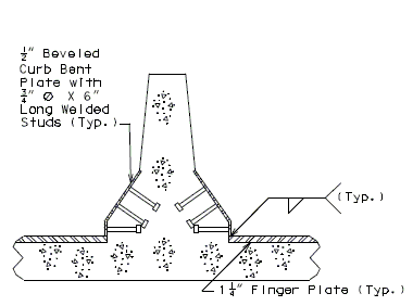
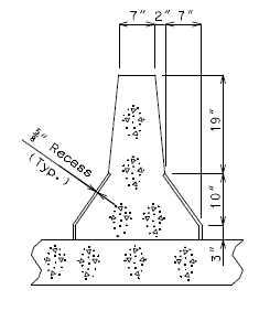
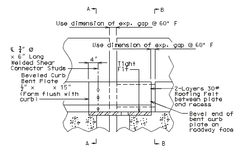
For the details not shown of median barrier bridge curb, see the safety barrier curb details. The Design Division Standard Plans (Concrete median barrier ), and the Bridge Design Layout.
 |
| ||||
| TYPICAL PART SECTION A-A | TYPICAL PART SECTION B-B | ||||
 |
| ||||
| PART ELEVATION OF BARRIER CURB (INTERMEDIATE BENT) |
