751.21 Prestressed Concrete Slab and Box Beams: Difference between revisions
m →751.21.3 Details: Per BR, updated broken links |
→751.21.3.6.1 Dimensions: updated per RR3915 |
||
| (8 intermediate revisions by 2 users not shown) | |||
| Line 108: | Line 108: | ||
===751.21.1.4 Span and Structure Lengths=== | ===751.21.1.4 Span and Structure Lengths=== | ||
The span and structure lengths for prestressed beams shall be in accordance with [[751. | The span and structure lengths for prestressed beams shall be in accordance with [[751.22_Prestressed_Concrete_I_Girders#751.22.1.4_Span_and_Structure_Lengths|EPG 751.22.1.4 Span and Structure Lengths]], except that skewed ends of prestressed beams shall be in accordance with [[751.21_Prestressed_Concrete_Slab_and_Box_Beams#751.21.3.2.1_Skewed_Ends|EPG 751.21.3.2.1 Skewed Ends]] instead of the coping requirements used for the I-Girders. | ||
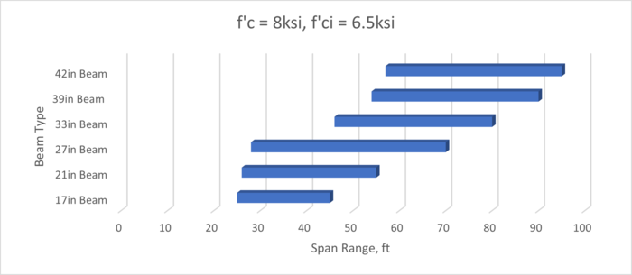
The following chart provides a general baseline for the maximum span lengths of prestressed spread box beams based off single span designs in accordance with LRFD, 9th Edition. The designs used for this chart use the maximum practical girder spacing (approximately 11’-6”). The chart was developed using designs that used standard materials and shapes. Increased span lengths are possible with modification to the materials, shapes, and/or girder spacings used. Increased span lengths are also likely for continuous span bridges. See Increasing Girder Capacity section above for more information. This chart shall be used for preliminary design only. | |||
'''Limitations of the Chart:''' | |||
This chart only contains data on designs with a concrete compressive strength equal to 8.0ksi, this is due to a lack of sufficient data for designs using a concrete compressive strength of 6.0ksi or 7.0ksi. | |||
<center><b><big>Prestressed Spread Box Beam Single Span Ranges</big></b></center> | |||
[[image:751.22.1.4_PS_Box_8ksi_07-23.png|700px|center]] | |||
===751.21.1.5 Constant and Varied Joint Filler Loads=== | ===751.21.1.5 Constant and Varied Joint Filler Loads=== | ||
| Line 282: | Line 291: | ||
Lower strands may be debonded at ends to reduce compressive stresses at the beam ends. | Lower strands may be debonded at ends to reduce compressive stresses at the beam ends. | ||
'''Adjacent Beams Only''' | '''Adjacent Beams Only''' | ||
| Line 300: | Line 308: | ||
'''Box Beams''' | '''Box Beams''' | ||
[[image:751.21.3.4.1 box | [[image:751.21.3.4.1 box 2023.jpg|center|800px]] | ||
<center> | <center>'''<big>STRAND ARRANGEMENT</big>'''</center> | ||
<center>+ Indicates prestressing strand</center> | |||
'''Voided Slab Beams''' | '''Voided Slab Beams''' | ||
[[image:751.21.3.4.1 voided.jpg|center| | [[image:751.21.3.4.1 voided 2023.jpg|center|800px]] | ||
<center>'''<big>STRAND ARRANGEMENT</big>'''</center> | |||
====751.21.3.4.2 Instructions==== | ====751.21.3.4.2 Instructions==== | ||
| Line 313: | Line 321: | ||
Strand instructions shall be indicated in the strand arrangement detail. | Strand instructions shall be indicated in the strand arrangement detail. | ||
[[image:751.21.3.4.2.jpg|center|650px]] | [[image:751.21.3.4.2 2023.jpg|center|650px]] | ||
<center>'''<font color="green">(b)</font color="green">''' Use 2'-0" for 27-inch box beams and smaller. Use 2'-6" for 33-inch box beams and larger.</center> | |||
<center> | <center> | ||
{| border="1" class="wikitable" style="margin: 1em auto 1em auto; text-align:center" | {| border="1" class="wikitable" style="margin: 1em auto 1em auto; text-align:center" | ||
| Line 353: | Line 361: | ||
====751.21.3.5 Camber, Haunching and Girder Steps==== | ====751.21.3.5 Camber, Haunching and Girder Steps==== | ||
For spread beams the camber, haunch, and stepping and sloping of top flange shall be in accordance with [[751.22 Prestressed Concrete I Girders#751.22.3. | For spread beams the camber, haunch, and stepping and sloping of top flange shall be in accordance with [[751.22 Prestressed Concrete I Girders#751.22.3.6 Camber, Haunching, and Stepping and Sloping of Top Flange|EPG 751.22.3.6 Camber, Haunching, and Stepping and Sloping of Top Flange]]. | ||
For adjacent beams a camber diagram is replaced with a slab thickness diagram. | For adjacent beams a camber diagram is replaced with a slab thickness diagram. | ||
| Line 381: | Line 389: | ||
Bearing length and thickness is by design. Bearings may vary on each side of bent. | Bearing length and thickness is by design. Bearings may vary on each side of bent. | ||
'''<font color="green">(e)</font color="green">''' 3¾" minimum. | '''<font color="green">(e)</font color="green">''' 3¾" minimum. With the approval of the SPM, the diaphragm may be made flush with substructure beams not greater than three feet wide. | ||
'''<font color="green">(f)</font color="green">''' Remove thickness for tapered bearings or when bearings vary on each side of bent. | '''<font color="green">(f)</font color="green">''' Remove thickness for tapered bearings or when bearings vary on each side of bent. | ||
| Line 448: | Line 456: | ||
Detail 3/8” beveled edges to run continuously across diaphragms that are flush with outside face of exterior beams at intermediate bents. Terminate bevel at diaphragms that extend past the outside face of beam. | Detail 3/8” beveled edges to run continuously across diaphragms that are flush with outside face of exterior beams at intermediate bents. Terminate bevel at diaphragms that extend past the outside face of beam. | ||
====751.21.3.11 Dowel Bars and Shear Blocks==== | ====751.21.3.11 Dowel Bars and Concrete Shear Blocks==== | ||
Dowel bars for fixed intermediate bents shall be in accordance with [[751.22 Prestressed Concrete I Girders#751.22.3. | Dowel bars for fixed intermediate bents shall be in accordance with [[751.22 Prestressed Concrete I Girders#751.22.3.7.4 Bent Details|EPG 751.22.3.7.4 Bent Details]]. | ||
Concrete shear blocks for open diaphragm bent caps and closed diaphragm bent caps shall be in accordance with [[751.22 Prestressed Concrete I Girders#751.22.3.13 Concrete Shear Blocks|EPG 751.22.3.13 Concrete Shear Blocks]]. | |||
====751.21.3.12 Miscellaneous==== | ====751.21.3.12 Miscellaneous==== | ||
| Line 475: | Line 483: | ||
'''Other Miscellaneous''' | '''Other Miscellaneous''' | ||
Other miscellaneous details shall be in accordance with [[751.22 Prestressed Concrete I Girders#751.22.3. | Other miscellaneous details shall be in accordance with [[751.22 Prestressed Concrete I Girders#751.22.3.14 Miscellaneous|EPG 751.22.3.14 Miscellaneous]]. | ||
[[Category:751 LRFD Bridge Design Guidelines]] | [[Category:751 LRFD Bridge Design Guidelines]] | ||
Latest revision as of 12:58, 31 July 2024
751.21.1 General
EPG 751.21 Prestressed Concrete Slab and Box Beams illustrates the general design procedure for prestressed concrete slab and box beams using AASHTO LRFD Bridge Design Specifications except as noted.
751.21.1.1 Application
Spread beams shall be composite with a reinforced concrete slab in accordance with EPG 751.10.1 Slab on Girder.
Adjacent beams shall be composite with a reinforced concrete slab with the slab thickness replacing the slab haunch component of a typical slab on girder structure. The slab shall be a minimum of 6 inches preferably with the barrier reinforcement tied to the slab reinforcement. The slab may also be a minimum of 5½ inches with the barrier cast with the beam.
A 1¾-inch minimum asphalt wearing surface may be used with non-composite adjacent beams for low volume routes.
751.21.1.2 Material Properties
Increasing Beam Capacity
The following allowable modification of material properties listed in order of increasing costs may be considered if required by design.
- 1. Increase concrete strength up to 8.0 ksi (f′c = 6.5 ksi) (readily producible by fabricator)
- 2. Increase concrete strength greater than 8.0 ksi (readily producible by fabricator)
- 3. Increase overall height (and void height or diameter, accordingly).
Class A-1 Concrete
Conventional concrete with the following compression strengths shall be used as required.
- f′c = 6.0 ksi (f′ci = 4.5 ksi) → f′c = 7.0 ksi (f′ci = 5.0 ksi) → f′c = 8.0 ksi (f′ci = 6.5 ksi)
The lowest concrete strength satisfying the demand shall be used.
High strength concrete with compressive strengths up to f′c =10 ksi (f′ci = 7.0 ksi) may be used with the permission of the Structural Project Manager or Structural Liaison Engineer. High strength concrete may increase costs due to production modifications necessary to obtain the required strength.
Modulus of Elasticity,
- Ec = 33,000K1wc1.5√f′c (f′c in ksi)
- Where: K1 = correction factor for source of aggregate = 1.0 unless determined by physical testing
- wc = 0.140 + 0.001f′c (f′c in ksi)
Prestressing Strands
Prestressing strands shall be Grade 270 uncoated, low relaxation, seven-wire strands in accordance with AASHTO M 203 with the following design properties.
| Ultimate tensile strength, fpu = 270 ksi | 1/2-Inch Strand: Diameter, dps = 0.5 in. and Area, Aps = 0.153 in.2 |
| Yield strength, fpy = 0.9fpu = 243 ksi | 0.6-Inch Strand: Diameter, dps = 0.6 in. and Area, Aps = 0.217 in.2 |
| Modulus of elasticity, Ep = 28,500 ksi | Maximum allowed force per strand, fpbtAps = 30.98 kips (1/2-inch strands) fpbtAps = 43.94 kips (0.6-inch strands) |
| Maximum allowed stress prior to transfer, fpbt = 0.75fpu = 202.5 ksi |
Total initial prestress force equals the number of strands multiplied by the required initial prestress force per strand.
Typically, the required initial prestress force per strand is the maximum allowed force per strand. Report on the plans the required number of strands by design and the total initial prestress force using EPG 751.50 Standard Detailing Notes H2c1.3.
Reinforcing Steel
Reinforcing steel shall be Grade 60 deformed bars in accordance with AASHTO M 31 with the following design properties.
| Yield strength, fy = 60.0 ksi | Modulus of elasticity, Es = 29,000 ksi |
All bars extending into slab shall be epoxy coated.
751.21.1.3 Geometric Properties
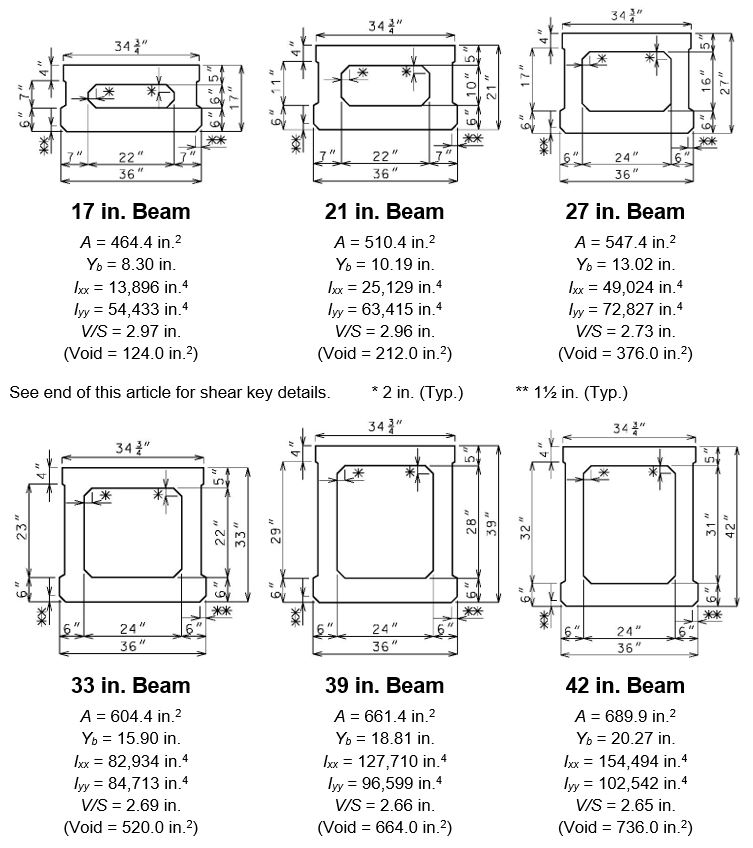
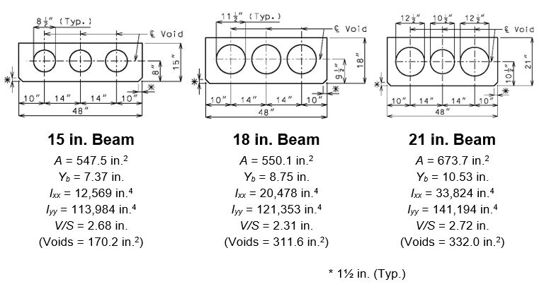
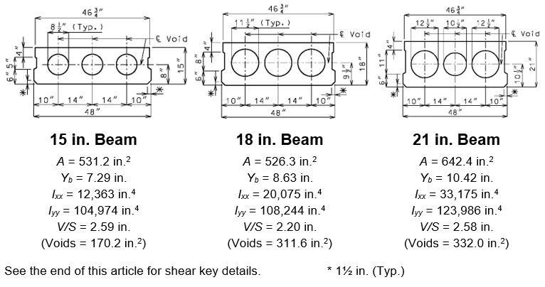
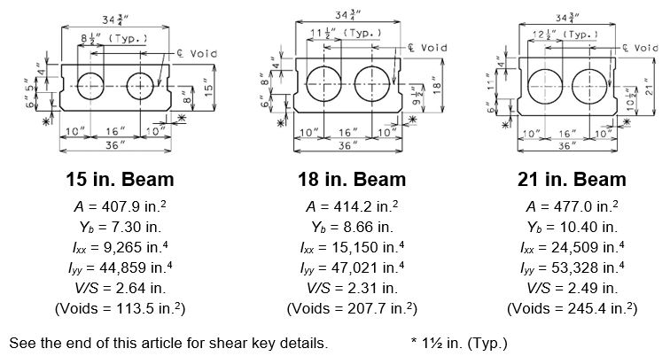
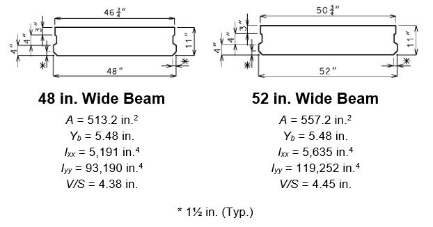
The following standard sections shall be used preferably because of their familiarity to local precast plants. These sections have been entered into the beam section libraries of in-house design software. Sections may be increased in height and void diameters may be adjusted if required but any deviation from the sections shall be discussed with Structural Project Manager or Structural Liaison Engineer.
Adjacent beams may be alternated from 3 feet to 4 feet wide to get the fewest number of beams possible for the required roadway width.
Standard sonovoids for voided slab beams are available with the following outside diameters: 8, 8.5, 9, 10, 10.5, 11, 12, 12.5, 14, 15.7 and 18 inches. Special sizes may be made if required. AASHTO minimum concrete thickness and cover shall be maintained.
Spread Box Beams
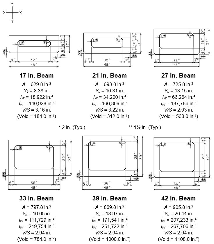
Adjacent Box Beams (4 feet wide)
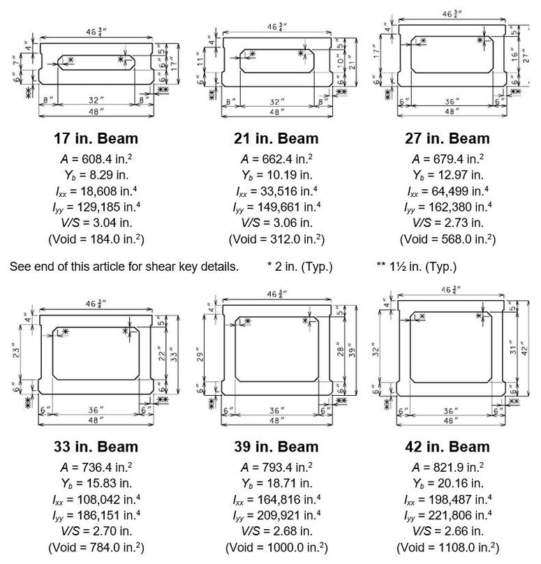
Adjacent Box Beams (3 feet wide):
Spread Voided Slab Beams
Adjacent Voided Slab Beams (4 feet wide):
Adjacent Voided Slab Beams (3 feet wide)
Solid Slab Beams
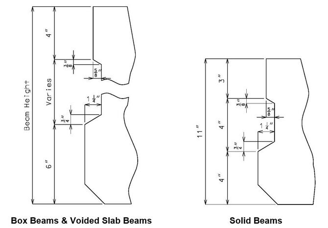
Shear Keys
751.21.1.4 Span and Structure Lengths
The span and structure lengths for prestressed beams shall be in accordance with EPG 751.22.1.4 Span and Structure Lengths, except that skewed ends of prestressed beams shall be in accordance with EPG 751.21.3.2.1 Skewed Ends instead of the coping requirements used for the I-Girders.
The following chart provides a general baseline for the maximum span lengths of prestressed spread box beams based off single span designs in accordance with LRFD, 9th Edition. The designs used for this chart use the maximum practical girder spacing (approximately 11’-6”). The chart was developed using designs that used standard materials and shapes. Increased span lengths are possible with modification to the materials, shapes, and/or girder spacings used. Increased span lengths are also likely for continuous span bridges. See Increasing Girder Capacity section above for more information. This chart shall be used for preliminary design only.
Limitations of the Chart:
This chart only contains data on designs with a concrete compressive strength equal to 8.0ksi, this is due to a lack of sufficient data for designs using a concrete compressive strength of 6.0ksi or 7.0ksi.
751.21.1.5 Constant and Varied Joint Filler Loads
The constant and varied joint filler loads for spread beam structures shall be in accordance with EPG 751.22.1.5 Constant and Varied Joint Filler Loads.
751.21.2 Design
The design shall be in accordance with the appropriate design guidance found in EPG 751.22.2 Design except as specified in this article.
751.21.2.1 Distribution Factors
Deck Superstructure Type (LRFD 4.6.2.2.1)
Spread beams (including voided slab beams) are considered as precast concrete boxes supporting components with a cast-in-place concrete slab deck, typical cross-section (b).
Adjacent beams composite with a reinforced concrete slab are considered as precast solid, voided, or cellular concrete boxes with shear keys supporting components with a cast-in-place concrete overlay deck, typical cross-section (f).
Adjacent beams with an asphalt wearing surface shall be considered as precast solid, voided, or cellular concrete box with shear keys and with or without transverse post-tensioning supporting components with an integral concrete deck, typical cross-section (g).
LRFD Exception for Shallow Spread Beams
The live load distribution factor for moment in interior beams specified for spread beams greater than or equal to 18 inches may be used for the 15- and 17-inch spread beams.
751.21.2.2 Pretensioned Anchorage Zones
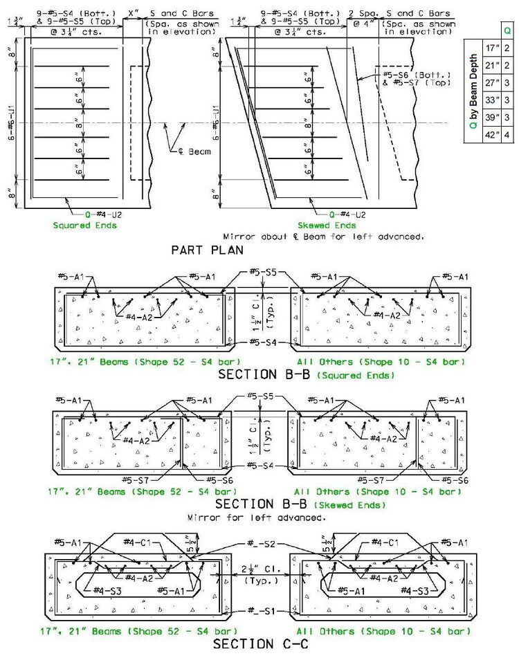
The bursting and spalling resistance in the ends of box beams shall be provided by vertical reinforcement (U1, S4 and S5 bars). The bursting and spalling resistance shall be based on LRFD 5.9.4.4.1 splitting resistance but modified based on strut-and-tie modeling developed by Davis, Buckner and Ozyildirimon (Dunkman et al. 2009).
The bursting and spalling resistance (Pr) at the service limit state shall meet both of the following:
- Within h/3 from the end of beam:
- Pr = fsAs ≥ 0.0375fpbt
- Within 3h/4 from the end of beam:
- Pr = fsAs ≥ 0.06fpbt
Where:
- fs = Stress in mild steel not exceeding 20 ksi
- As = Total area of vertical reinforcement within specified distances; where h is overall beam height.
- fpbt = Prestressing force immediately prior to transfer
Confinement Reinforcement
In accordance with LRFD Article 5.9.4.4.2 confinement reinforcement is not required for box beams and voided and solid slab beams. Rather the provided top and bottom transverse reinforcement shall be anchored into the web of the beam.
751.21.2.3 Temporary Tensile Stress Reinforcement
The #5-A1 and #4-A2 bars shall resist the tensile force in a cracked section computed on the basis of an uncracked section.
Required Steel Area: A1 + A2 = Tf/fs
Where:
- fs = 0.5fy ≤ 30 ksi, allowable tension stress of mild steel, (ksi)
- Tf = Resultant of total tensile force computed on the basis of an uncracked section, (kips)
Designer shall verify the A2 bars are actually in tension before including them in the check. Additional A1 bars may be needed where there isn’t enough deadload to put the top of the beam into compression.
Reinforcement shall be designed and spliced using f’ci in accordance with EPG 751.5.9.2.8 Development and Lap Splices.
751.21.3 Details
Green items shown in the details of this article are detailing guidance only and shall not be shown on the plans.
751.21.3.1 Standard Drawings
The following standard drawings have been developed.
| Bridge Standard Drawings |
| Prestressed Box Beams |
751.21.3.2 Beam Ends
751.21.3.2.1 Skewed Ends
Spread Beams
To eliminate the need to widen end bents or lessen the widening needed for highly skewed substructures a skewed-end beam may be used. Skewed ends shall be skewed at 15 degrees regardless of the skew of the substructure. The skew is set at 15 degrees to simplify fabrication and limited to 15 degrees to help prevent warping of the ends due to eccentric prestress forces.
The face of box beam voids shall be parallel to the skewed ends (also at 15 degrees) with a 4-inch chamfer at the acute corner. The face of voided slab beam voids shall not be skewed but the ends of each void shall be staggered to align with the skewed end.
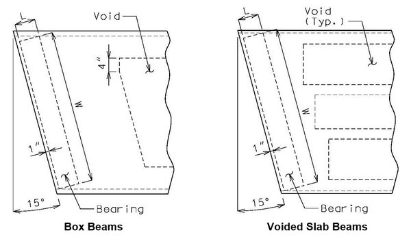
Skewed-end beams are typically recommended for substructures skewed greater than 20 degrees.
Adjacent Beams
Skewed ends for adjacent beams shall be skewed to match the substructure (skewed no greater than 30 degrees).
751.21.3.2.2 End Blocks Lengths and Weights
End blocks are required for stress transfer to the bearings and to provide a location for the required lifting loops. The following minimum lengths shall be provided.
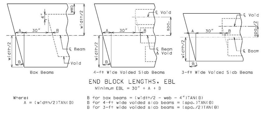
The following end block lengths shall be used in the part plan of beam and the following weights are provided for use in design. The weights provided are based on the void area and wc = 153 lb/ft3 (f’c = 8.0 ksi).
| End Block Lengths (EBL) & Weights | |||||||
|---|---|---|---|---|---|---|---|
| Squared Ends, EBL = 30" | 15° Skewed Ends | ||||||
| Type | Beam Depth | 4-ft Wide Weight | 3-ft Wide Weight | EBL | 4-ft Wide Weight | EBL | 3-ft Wide Weight |
| Box Beams | 17 in. | 489 lb | 329 lb | 40 in. | 652 lb | 37 in. | 406 lb |
| 21 in. | 829 lb | 563 lb | 40 in. | 1105 lb | 37 in. | 695 lb | |
| 27 in. | 1509 lb | 999 lb | 40 in. | 2012 lb | 37 in. | 1232 lb | |
| 33 in. | 2083 lb | 1381 lb | 40 in. | 2777 lb | 37 in. | 1704 lb | |
| 39 in. | 2656 lb | 1764 lb | 40 in. | 3542 lb | 37 in. | 2175 lb | |
| 42 in. | 2943 lb | 1955 lb | 40 in. | 3924 lb | 37 in. | 2411 lb | |
| Voided Slab Beams | 15 in. | 452 lb | 301 lb | 40 in. | 603 lb | 37 in. | 372 lb |
| 18 in. | 828 lb | 552 lb | 40 in. | 1104 lb | 37 in. | 680 lb | |
| 21 in. | 882 lb | 652 lb | 40 in. | 1176 lb | 37 in. | 804 lb | |
| Three-foot wide beams are only used as adjacent beams. End block lengths and weights for skewed-end adjacent beams of different skews shall be calculated using specified formulas for minimum end-block length. | |||||||
751.21.3.2.3 Bearing Plates
The following detail shall be provided on the plans.

751.21.3.2.4 Lifting Loops
The note in EPG 751.50 H2c. Prestressed Girders and Beams specifying the fabricator’s responsibility for the lifting devices shall be placed in the general notes of the beam sheet.
Details of lifting loops are not required on plans.
751.21.3.3 Beam Reinforcement
Concrete cover, minimum spacing and bend diameter shall be in accordance with EPG 751.22.3.1 Reinforcement Criteria.
The #5-S4 and S5 bars satisfy bursting and spalling requirements in accordance with EPG 751.21.2 Design for the strand arrangements shown is this article and on the Bridge Standard Drawings. Shear capacity shall be verified by design.
The size and spacing of S1 and S2 bars shall be determined by design. The use of #4 or #5 bars is at the discretion of the Structural Project Manager if both available diameters meet demand. No. 6 bars shall not be used for S1 and S2 bars due to interference with strands and other reinforcement.
751.21.3.3.1 Spread Box Beams
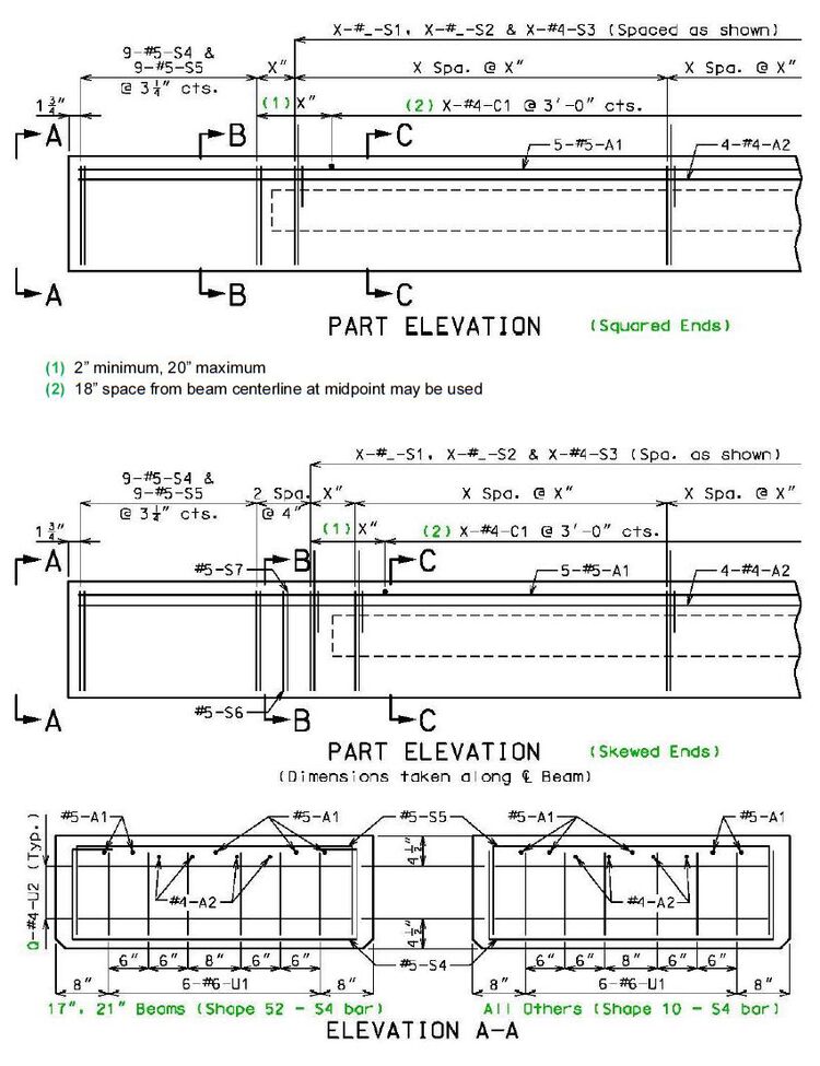
Bending Diagrams
Dimensions shown are out to out. Use symmetry for dimensions not shown. Use "ɑ" bars for squared-end beams. Use "b" bars for skewed-end beams.
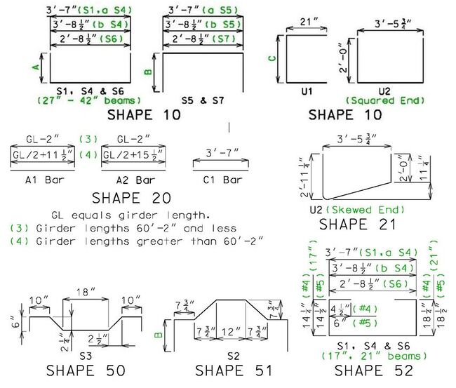
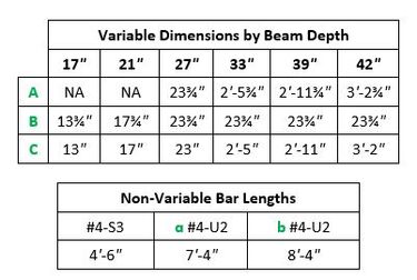 |
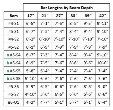 |
For beams that have excessive haunch or beam steps, create new S2 bars and adjust heights in one-inch increments or provide #4 hairpin bars in accordance with EPG 751.10.1.14 Girder and Beam Haunch Reinforcement to ensure at least 2-inch embedment into slab.
751.21.3.4 Prestressing Strands
Strands shall not be placed over voids since it may impede formation of void.
Strands shall not be draped (harped).
Lower strands may be debonded at ends to reduce compressive stresses at the beam ends.
Adjacent Beams Only
Strands shall avoid the anchor bolt wells and post-tensioning blockout.
The number of strands in the bottom row shall be equal to or less than the second row to provide for better redundancy against corrosion that is more prevalent in adjacent beams.
751.21.3.4.1 Arrangements
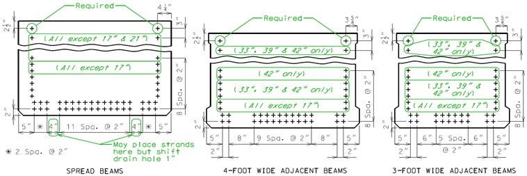
The following detail shall be provided on the plans.
Actual arrangement shall be determined by design. Remove symbols as needed.
See standard drawings for strand locations that are not available when vent pipe is required.
Box Beams
Voided Slab Beams

751.21.3.4.2 Instructions
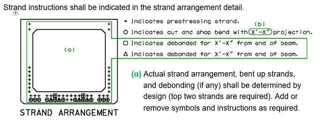
Strand instructions shall be indicated in the strand arrangement detail.
| Required Number of Bent-Up Strands | ||
|---|---|---|
| Beam | 1/2 inch | 0.6 inch |
| 17”, 21”, 27” Spread Box | 14 | 10 |
| 33”, 39”, 42” Spread Box | 12 | 8 |
If the number of strands available per design is less than the requirement for bent-up strands consider the following:
- 1. Add extra strands and re-check design stresses.
- 2. Add extra strands and reduce the jacking stress to keep a similar total design force.
- 3. Design bent-up strands using the actual project criteria.
The criteria for the specified number of bent-up strands:
- 1. 8½-inch thick deck slab
- 2. Maximum allowed haunch plus two ½-inch beam steps
- 3. 12-foot effective slab width.
The required number of bent-up strands shall be determined by design for other beam types or for spread box beams that exceed specified criteria.
The notes for strand instructions located in EPG 751.50 H2c. Prestressed Girders and Beams shall be placed near detail as applicable.
751.21.3.4.3 Beam Ends
The following detail shall be provided on the plans:
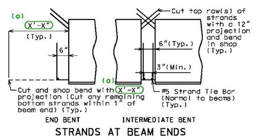
- (ɑ) Use 2'-0" for 27-inch box beams and smaller. Use 2'-6" for 33-inch box beams and larger.
751.21.3.5 Camber, Haunching and Girder Steps
For spread beams the camber, haunch, and stepping and sloping of top flange shall be in accordance with EPG 751.22.3.6 Camber, Haunching, and Stepping and Sloping of Top Flange.
For adjacent beams a camber diagram is replaced with a slab thickness diagram.
751.21.3.6 Closed Intermediate Bent Diaphragms
The details in this article are applicable for continuous slab superstructures for fixed and expansion intermediate bents as specified.
751.21.3.6.1 Dimensions
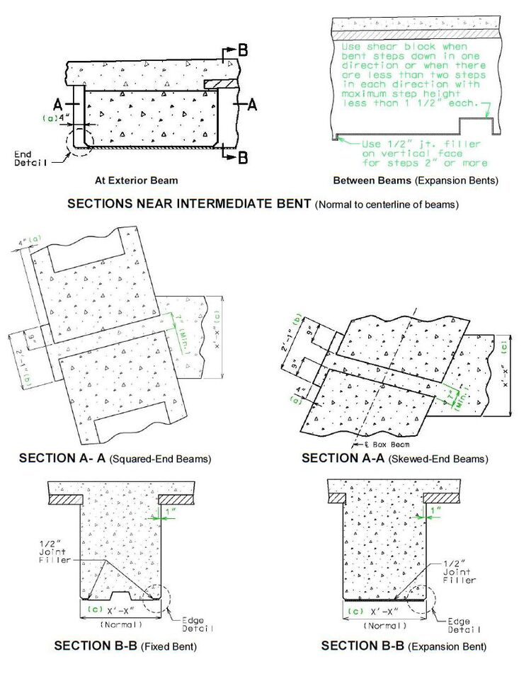
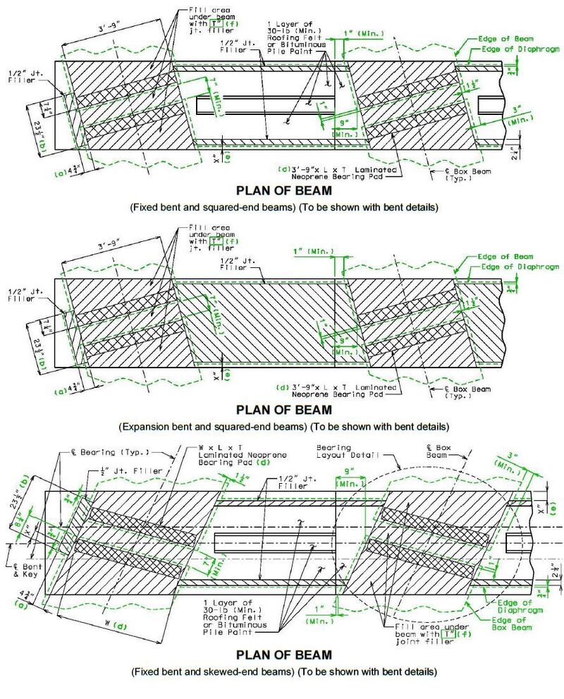
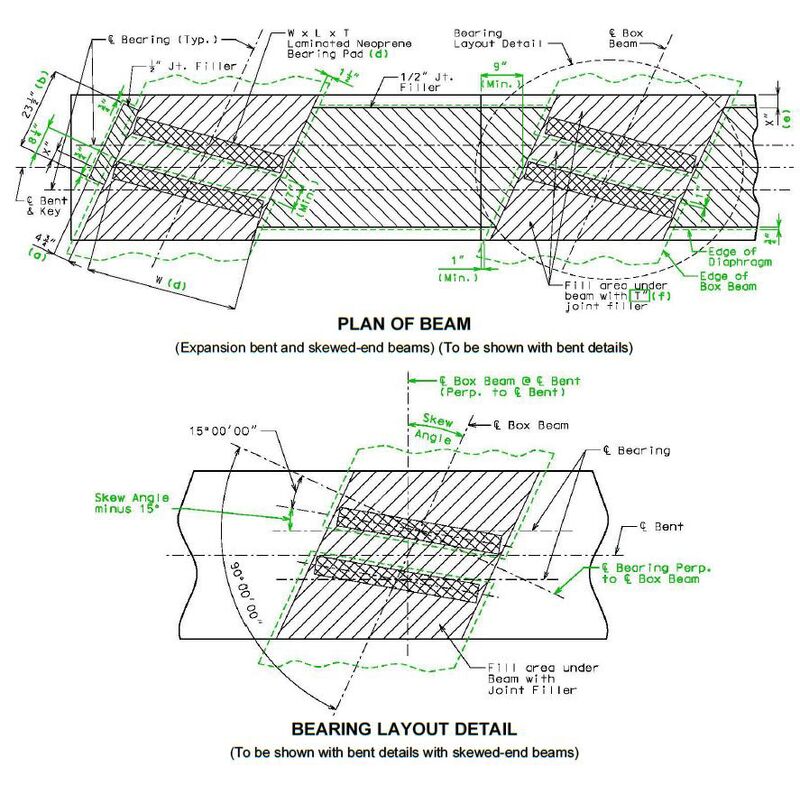
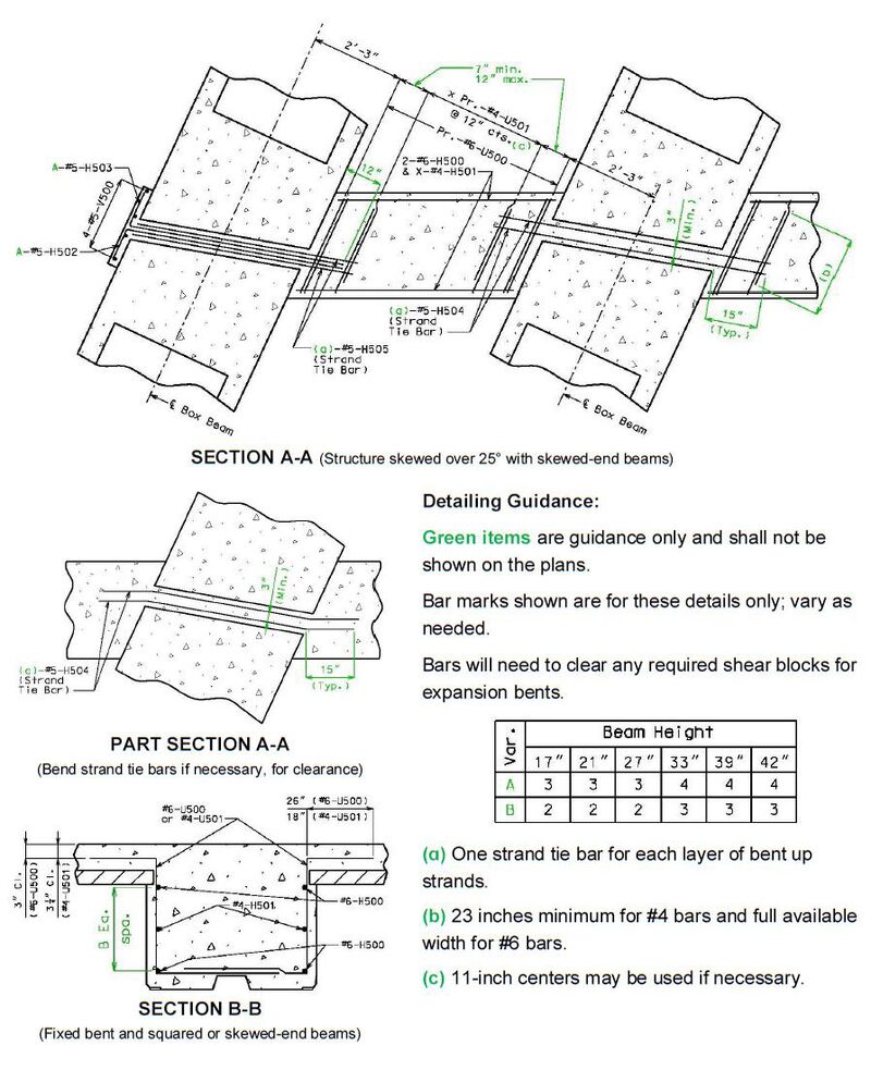
Detailing Guidance: Green items are guidance only and shall not be shown on the plans.
For End Detail and Edge Detail, see EPG 751.21.3.6.4.
(ɑ) Minimum distance. Will need to be increased on one side of the bent for curved alignments. Will need to add "(Min.)" to dimension in the elevation detail or replace dimension with "Varies".
(b) Dimension based on a tangent alignment and minimum 7 inches between the ends of girders (along beam centerline for skewed-end beams). Will vary for curved alignments.
(c) Diaphragm shall be 2'-6" wide unless skew requires wider diaphragm to accommodate coil ties (6” increments).
(d) "W" is width of bearing and for 4-foot wide squared-end beams is equal to 3’-9" (width of box beam minus 3 inches). Width of bearing for 4-foot wide skewed-end beams is equal to 3’-8” for bearing lengths “L” less than 9 inches. Bearing length and thickness is by design. Bearings may vary on each side of bent.
(e) 3¾" minimum. With the approval of the SPM, the diaphragm may be made flush with substructure beams not greater than three feet wide.
(f) Remove thickness for tapered bearings or when bearings vary on each side of bent.
751.21.3.6.2 Coil Tie Rods
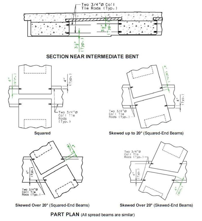
751.21.3.6.3 Reinforcement
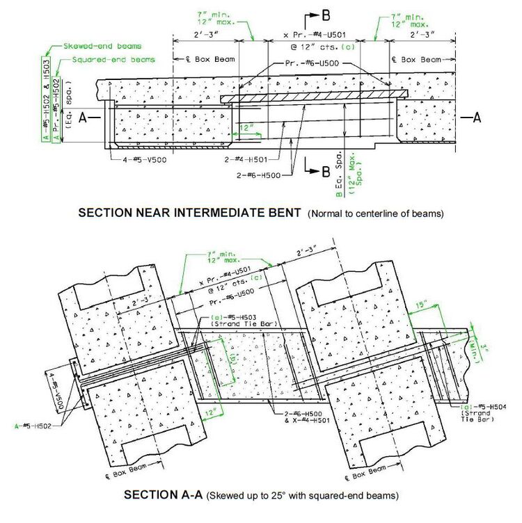
751.21.3.6.4 End and Edge Details
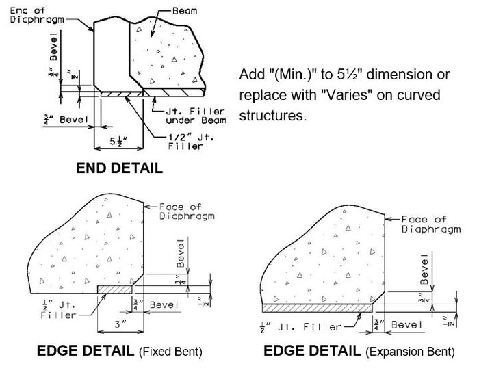
For location of End Detail and Edge Detail, see EPG 751.21.3.6.1 Dimensions.
751.21.3.7 Coil Ties
The following detail shall be provided on the plans for spread beams.
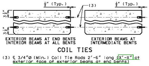
Detail shown is for integral end bents. Revise subheadings accordingly for non-integral end bents.
Include underline portion with end spans when both interior and exterior beams are detailed on the same sheet and the 2’-6” long tie rod will not fit in the exterior diaphragm portion.

The coil tie notes located in EPG 751.50 H2c. Prestressed Girders and Beams shall be placed near detail as applicable.
751.21.3.8 Vent Pipes for Stream Crossings
Due to the buoyancy of the voids, adjacent box or voided beam bridges shall not be used where the structure will be submerged.
Spread beam bridges may be used with the approval of the SPM or SLE in situations where the structure will be submerged. In these situations, a vent pipe shall be provided through an internal diaphragm at the midpoint of each beam in order to vent the bay area between the spread beams.
The vent pipe and internal diaphragm shall not be provided when not required.
The weights provided are based on the void area, volume of vent pipe, and wc = 153 lb/ft3 (f’c = 8.0 ksi).
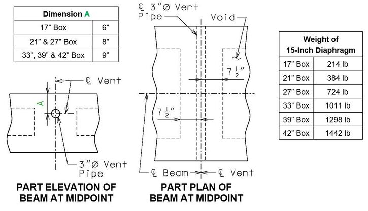
Do not place a set of S bars at centerline of beam at midpoint when vent pipes are provided.
751.21.3.9 Top Surface Preparation for Adjacent Beams
Adjacent beams shall be protected with a reinforced concrete wearing surface (preferred) or an asphalt wearing surface (roadways with low average daily traffic, usually less than 400 ADT).
For concrete wearing surfaces, the top surface of the beams shall be roughened to improve bond between the wearing surface and the beam.
For asphalt wearing surfaces, the top surface of the beams shall be float finished and protected with a waterproof membrane. Such a finish minimizes the following:
- 1. Amount of preparation and material needed for the membrane
- 2. Potential puncture of the membrane due to unforeseen thin spots
- 3. Movement of the membrane (particularly those with a membrane applied over an asphalt binder) during paving operations.
The bridge special provision for waterproof membranes shall be required with asphalt wearing surfaces.
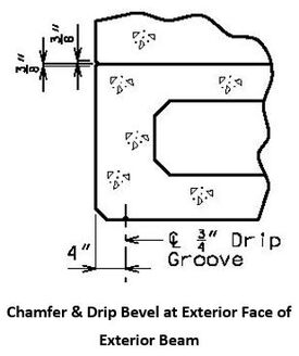
751.21.3.10 Exterior Beam Bevel at Slab Edge and Drip Bevel
Show detail on the plans for spread and adjacent beams where the outside face of slab is flush with the outside face of the exterior beam.
The plans for slab and barrier shall be modified appropriately.
Detail 3/8” beveled edges to run continuously across diaphragms that are flush with outside face of exterior beams at intermediate bents. Terminate bevel at diaphragms that extend past the outside face of beam.
751.21.3.11 Dowel Bars and Concrete Shear Blocks
Dowel bars for fixed intermediate bents shall be in accordance with EPG 751.22.3.7.4 Bent Details.
Concrete shear blocks for open diaphragm bent caps and closed diaphragm bent caps shall be in accordance with EPG 751.22.3.13 Concrete Shear Blocks.
751.21.3.12 Miscellaneous
Post Tension Rods
Tension rods for post tensioning if required should be placed at the beam ends and at midpoints for spans less than 40 feet. Tension rods may be placed at one-third points for spans 40 feet or greater.
Anchor Dowel Bars
Anchor dowel bars required for adjacent beams shall be cast in place preferably but may be drilled into the beam cap. Typically the drilled holes are 2 inches in diameter for a one-inch diameter anchor dowel.
Anchor dowels are typically located at 9 inches (center) from side of beam for 36-inch wide beams and 10 inches for 48 and 52-inch wide beams.
Void Drains
Three-quarter-inch drains shall be provided near ends of each void, one near each side of the void for box beams.
Optional Void Vent Holes
Optional one-quarter-inch vent holes shall be allowed for box beams near ends of each void located at the centerline of the beam.
Other Miscellaneous
Other miscellaneous details shall be in accordance with EPG 751.22.3.14 Miscellaneous.