751.10 General Superstructure: Difference between revisions
→751.10.2.4 Transparent Forms: updated per RR3947 |
|||
| (22 intermediate revisions by 2 users not shown) | |||
| Line 316: | Line 316: | ||
'''Slab Thickness''' | '''Slab Thickness''' | ||
For multi-span bridges the slab portion between girders shall be 8 1/2” thick for both the full depth cast-in-place concrete and partial depth precast prestressed concrete panel standard slabs. For new single-span bridges the slab thickness may be reduced to 8 inches.. | For multi-span bridges the slab portion between girders shall be 8 1/2” thick for both the full depth cast-in-place concrete and partial depth precast prestressed concrete panel standard slabs. For new single-span bridges the slab thickness may be reduced to 8 inches for full depth cast-in-place decks. A minimum 5 1/2-inch cast-in place topping is required when precast panels are used. | ||
'''Design Cases''' | '''Design Cases''' | ||
| Line 408: | Line 408: | ||
'''Determining Dead Load''' | '''Determining Dead Load''' | ||
For slab analysis assume that slab is full depth cast-in-place (CIP). The maximum negative and positive dead load moment may be taken to be: | |||
Continuous over 4 girders (equally spaced): | Continuous over 4 girders (equally spaced): | ||
| Line 493: | Line 493: | ||
:{| | :{| | ||
|At Bottom of CIP slabs||width="20"| ||1.00 inch | | At Bottom of CIP slabs || width="20"| ||1.00 inch | ||
|- | |- | ||
|Bottom of CIP slab over P/C P/S panels|| ||1.00 inch | | Bottom of CIP slab over P/C P/S panels || || 1.00 inch | ||
|- | |- | ||
|Top reinforcing (multi-span bridges)|| ||3 inches preferred, 2 3/4 inches absolute | | Top reinforcing (multi-span bridges) || || 3 inches preferred, 2 3/4 inches absolute | ||
|- | |- | ||
|Top reinforcing (single span bridges)|| ||3 inches preferred | | Top reinforcing (single span bridges) || || 3 inches preferred | ||
|} | |} | ||
For new single span bridges that utilize an 8-inch slab thickness, the clear cover to the top longitudinal reinforcing shall be 2 5/8 inches. | For new single span bridges with full depth cast-in-place decks that utilize an 8-inch slab thickness, the clear cover to the top longitudinal reinforcing shall be 2 5/8 inches. | ||
For redecks where the slab thickness is required to be less than 8 1/2 inches due to grade restrictions, the absolute min to the top reinforcing steel is 2 inches. | For redecks where the slab thickness is required to be less than 8 1/2 inches due to grade restrictions, the absolute min to the top reinforcing steel is 2 inches. | ||
| Line 614: | Line 614: | ||
::1/20 of the clear span (centerline to centerline of pier) | ::1/20 of the clear span (centerline to centerline of pier) | ||
:Continuing reinforcement shall extend not less than the development length, l< | :Continuing reinforcement shall extend not less than the development length, l<sub>d</sub>, beyond the point where reinforcement is no longer required to resist flexure. | ||
:At least one third of the total tension reinforcement provided for negative moment at a support shall have an embedment length beyond the point of inflection not less than: | :At least one third of the total tension reinforcement provided for negative moment at a support shall have an embedment length beyond the point of inflection not less than: | ||
| Line 630: | Line 630: | ||
'''Slab Thickness''' | '''Slab Thickness''' | ||
For new multi-span bridges the overhang slab thickness shall be 8½ inches. For new single span bridges the overhang slab thickness | For new multi-span bridges the overhang slab thickness shall be 8½ inches. For new single span bridges the overhang slab thickness shall match the depth used between girders. | ||
| Line 685: | Line 685: | ||
|style="border-bottom:0px"|[[Image:751.10 design case 1 slab design loading.gif]] | |style="border-bottom:0px"|[[Image:751.10 design case 1 slab design loading.gif]] | ||
|- | |- | ||
|style="border-top:0px"| | |style="border-top:0px"|Barrier Loading | ||
|style="border-top:0px"|Slab Design Loading | |style="border-top:0px"|Slab Design Loading | ||
|- | |- | ||
| Line 770: | Line 770: | ||
'''Special Considerations for Light Poles''' | '''Special Considerations for Light Poles''' | ||
[[751.12 Barriers, Curbs and Fences#751.12.1.2.7 Light Poles|Standard details]] for mounting 30-foot and 45-foot Type B light poles on concrete barrier are provided. At the barrier-to-slab interface, the force effect of wind on the light pole ''(STRENGTH - III)'' with 90 mph wind is less than that due to ''EXTREME EVENT-II'' (TL-4) on concrete barrier. Therefore, reinforcing designed for ''EXTREME EVENT-II'' (TL-4) load combination will be adequate. | [[751.12 Barriers, Curbs and Fences#751.12.1.2.7 Details of Mounting Light Poles on Safety Barrier Curbs|Standard details]] for mounting 30-foot and 45-foot Type B light poles on concrete barrier are provided. At the barrier-to-slab interface, the force effect of wind on the light pole ''(STRENGTH - III)'' with 90 mph wind is less than that due to ''EXTREME EVENT-II'' (TL-4) on concrete barrier. Therefore, reinforcing designed for ''EXTREME EVENT-II'' (TL-4) load combination will be adequate. | ||
=== 751.10.1.7 Standard Bridge Deck Details === | === 751.10.1.7 Standard Bridge Deck Details === | ||
| Line 785: | Line 785: | ||
|} | |} | ||
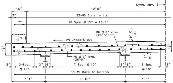
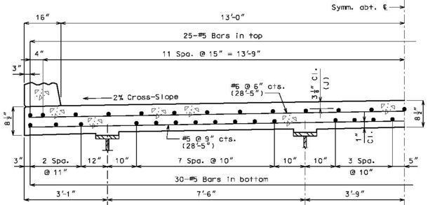
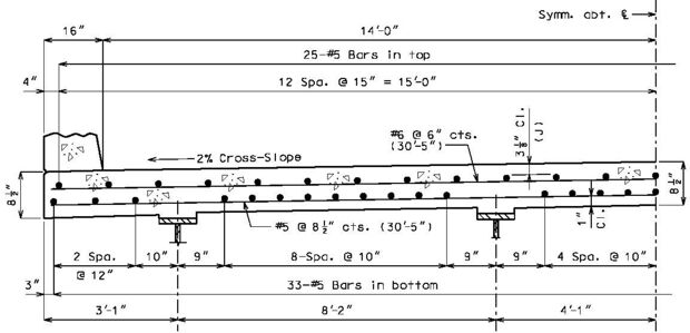
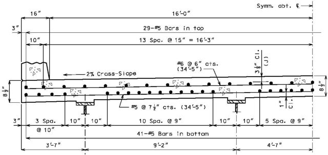
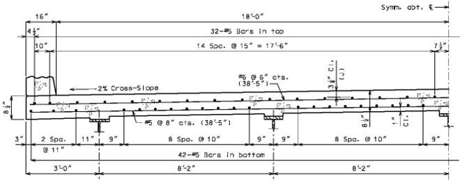
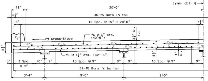
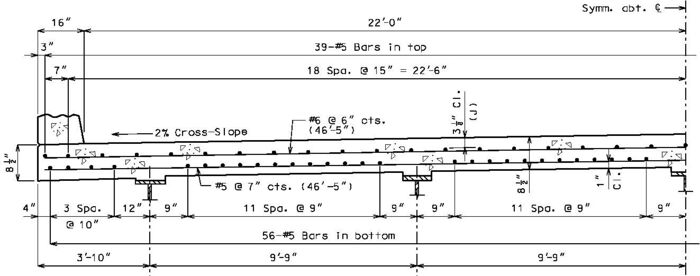
====751.10.1.7.1 Standard Full Depth CIP Bridge Deck Slabs Using Conventional | ==== 751.10.1.7.1 Standard Full Depth CIP Bridge Deck Slabs Using Conventional Forms, SIP Corrugated Steel Forms, or SIP Transparent Forms ==== | ||
{| border="0" cellpadding="5" cellspacing="0" align="center" style="textalign:left" | {| border="0" cellpadding="5" cellspacing="0" align="center" style="textalign:left" | ||
|-valign="top" | |- valign="top" | ||
|width="40"|(A)||Full depth CIP (cast-in-place) slab cross sections with reinforcement designed for the HL-93 live load are shown for nine standard roadway widths. | | width="40" | (A) || Full depth CIP (cast-in-place) slab cross sections with reinforcement designed for the HL-93 live load are shown for nine standard roadway widths. | ||
|-valign="top" | |- valign="top" | ||
|(B)||Slab design includes an allowance for 35 psf future wearing surface. | | (B) || Slab design includes an allowance for 35 psf future wearing surface. | ||
|-valign="top" | |- valign="top" | ||
|(C)||Slab design is based on ultimate strength design, f’c equals 4 ksi, and Grade 60 reinforcing steel. | | (C) || Slab design is based on ultimate strength design, f’c equals 4 ksi, and Grade 60 reinforcing steel. | ||
|-valign="top" | |- valign="top" | ||
|(D)||When the flange width exceeds the bottom longitudinal reinforcement spacing over the girder, reduce the bar spacing between the girders and increase the bar spacing over the girder to clear the flange edges. | | (D) || When the flange width exceeds the bottom longitudinal reinforcement spacing over the girder, reduce the bar spacing between the girders and increase the bar spacing over the girder to clear the flange edges. | ||
|-valign="top" | |- valign="top" | ||
|(E)||When the structure is on grade, determine lengths of the longitudinal reinforcement in the slab and barrier from the actual length. | | (E) || When the structure is on grade, determine lengths of the longitudinal reinforcement in the slab and barrier from the actual length. | ||
|-valign="top" | |- valign="top" | ||
|(F)||For slab design, the centerline of wheels is located one foot from face of barrier or curbs. | | (F) || For slab design, the centerline of wheels is located one foot from face of barrier or curbs. | ||
|-valign="top" | |- valign="top" | ||
|(G)||Standard slabs were designed assuming 12-inch minimum flanges and are applicable for plate girders, wide flange beams, MoDOT prestressed girders, and NU and bulb-tee girders when slab drains are not required or slab cantilevers that are less than 44 inches in the case of bulb-tee girders. | | (G) || Standard slabs were designed assuming 12-inch minimum flanges and are applicable for plate girders, wide flange beams, MoDOT prestressed girders, and NU and bulb-tee girders when slab drains are not required or slab cantilevers that are less than 44 inches in the case of bulb-tee girders. | ||
|-valign="top" | |- valign="top" | ||
|(H)||The bridge roadway width, from gutter line to gutter line, shall be the same as the roadway width (from outside edge of shoulder to outside edge of shoulder). | | (H) || The bridge roadway width, from gutter line to gutter line, shall be the same as the roadway width (from outside edge of shoulder to outside edge of shoulder). | ||
|-valign="top" | |- valign="top" | ||
|(I)||Standard slab designs do not include the effect of features not shown (i.e. sidewalk, fence, utilities, etc…) except for future wearing surface. | | (I) || Standard slab designs do not include the effect of features not shown (i.e. sidewalk, fence, utilities, etc…) except for future wearing surface. | ||
|-valign="top" | |- valign="top" | ||
|(J)|| Guidance for minimum concrete cover for top slab bars is 3 inches and shall meet [ | | (J) || Guidance for minimum concrete cover for top slab bars is 3 inches and shall meet [[751.5 Structural Detailing Guidelines#751.5.9.2 Reinforcing Steel|EPG 751.5.9.2 Reinforcing Steel]]. This cover is required for #6 top slab bars used in tandem. An exception is made for larger top slab bars, e.g. #8 longitudinal bars where cover will need to be reduced to 2 3/4 inches. | ||
|-valign="top" | |- valign="top" | ||
| (K) || The standard slab reinforcement shown in this article for HL-93 live load were designed using dead loads given in [[#751.10.2.3 Corrugated Steel Forms |EPG 751.10.2.3]] for stay-in-place corrugated steel forms. | | (K) || The standard slab reinforcement shown in this article for HL-93 live load were designed using dead loads given in [[#751.10.2.3 Corrugated Steel Forms|EPG 751.10.2.3]] for stay-in-place corrugated steel forms and [[751.10_General_Superstructure#751.10.2.4_Transparent_Forms|EPG 751.10.2.4]] for stay-in-place transparent forms. | ||
|} | |} | ||
| Line 875: | Line 875: | ||
{| border="0" cellpadding="5" cellspacing="0" align="center" style="textalign:left" | {| border="0" cellpadding="5" cellspacing="0" align="center" style="textalign:left" | ||
|-valign="top" | |-valign="top" | ||
|width="40"|(A)||Precast prestressed panel bridge deck cross sections are not shown. | |width="40"|(A)||Precast prestressed panel bridge deck cross sections are not shown. A partial depth cast-in-place deck shall consist of three-inch precast prestressed panel forms with a 5 1/2-inch minimum cast-in-place concrete topping. For details, use standard full depth CIP deck cross sections and top deck reinforcement only replacing the bottom layer of reinforcement between the girders with panels. For nonstandard roadway cross sections, the deck slab is designed like a full depth CIP deck slab and detailed as before for standard roadway cross sections within the limits of panel width given in [[#751.10.2.1 Precast Prestressed (P/C P/S) Concrete Panel Forms - Design |EPG 751.10.2.1 Precast Prestressed Concrete Panel Forms - Design]]. Cantilever reinforcement details for partial depth P/C P/S panel deck slabs are shown below. | ||
|-valign="top" | |-valign="top" | ||
|(B)||Slab design includes an allowance for 35 psf future wearing surface. | |(B)||Slab design includes an allowance for 35 psf future wearing surface. | ||
| Line 889: | Line 889: | ||
|(G)||Standard slabs were designed assuming 12-inch minimum flanges and are applicable for plate girders, wide flange beams, MoDOT prestressed girders, and NU and bulb-tee girders when slab drains are not required or slab cantilevers that are less than 44 inches in the case of bulb-tee girders. | |(G)||Standard slabs were designed assuming 12-inch minimum flanges and are applicable for plate girders, wide flange beams, MoDOT prestressed girders, and NU and bulb-tee girders when slab drains are not required or slab cantilevers that are less than 44 inches in the case of bulb-tee girders. | ||
|-valign="top" | |-valign="top" | ||
|(H)||When a barrier is permanently required on the structure, other than at the edge of slab or where precast prestressed panels are not used for other reasons, panels shall not be used in the bay underneath the barrier. Check reinforcement in the full depth CIP bay for collision and wheel loads on opposite faces of the barrier and provide suitable anchorage of the barrier reinforcing steel. | |(H)||When a barrier is permanently required on the structure, other than at the edge of slab or where precast prestressed panels are not used for other reasons, panels shall not be used in the bay underneath the barrier. Stay-in-place transparent forms are preferred in the bay underneath the barrier to allow for inspection of the bottom of deck after barrier collisions. Check reinforcement in the full depth CIP bay for collision and wheel loads on opposite faces of the barrier and provide suitable anchorage of the barrier reinforcing steel. | ||
|-valign="top" | |-valign="top" | ||
|(J)||The bridge roadway width, from gutter line to gutter line, shall be the same as the roadway width (from outside edge of shoulder to outside edge of shoulder). | |(J)||The bridge roadway width, from gutter line to gutter line, shall be the same as the roadway width (from outside edge of shoulder to outside edge of shoulder). | ||
| Line 897: | Line 897: | ||
|(L)||Standard slab designs do not include the effect of features not shown (i.e. sidewalk, fence, utilities, etc…) except for future wearing surface. | |(L)||Standard slab designs do not include the effect of features not shown (i.e. sidewalk, fence, utilities, etc…) except for future wearing surface. | ||
|-valign="top" | |-valign="top" | ||
|(M)||Guidance for minimum concrete cover for top slab bars is 3 inches and shall meet [ | |(M)||Guidance for minimum concrete cover for top slab bars is 3 inches and shall meet [[751.5 Structural Detailing Guidelines#751.5.9.2 Reinforcing Steel|EPG 751.5.9.2 Reinforcing Steel]]. This cover is required for #6 top slab bars used in tandem. An exception is made for larger top slab bars, e.g. #8 longitudinal bars where cover will need to be reduced to 2 3/4 inches. | ||
|} | |} | ||
| Line 949: | Line 949: | ||
=== 751.10.1.11 Slab Elevations === | === 751.10.1.11 Slab Elevations === | ||
Slab elevations are used to determine haunching at the tenth points of steel and prestressed girder or beam spans | Slab elevations are used to determine haunching at the tenth points of steel and prestressed girder or beam spans seventy-five feet in length or longer. Spans shorter than 75 feet long use quarter points. | ||
'''Theoretical Bottom of Slab Elevations at Centerline of Girder (Prior to Forming for Slab)''' | '''Theoretical Bottom of Slab Elevations at Centerline of Girder (Prior to Forming for Slab)''' | ||
| Line 1,005: | Line 1,005: | ||
Use of retarder is required for prestressed structures and a Case II sequence * is normally required. The minimum rate of pour will be determined by the 20 feet per hour minimum finishing rate but shall not be less than 25 cubic yards per hour. For span lengths over 80 feet or special structures (segmental, etc.), see Structural Project Manager. | Use of retarder is required for prestressed structures and a Case II sequence * is normally required. The minimum rate of pour will be determined by the 20 feet per hour minimum finishing rate but shall not be less than 25 cubic yards per hour. For span lengths over 80 feet or special structures (segmental, etc.), see Structural Project Manager. | ||
:<math>\,W</math> = Slab width (out to out of barriers, or width being poured)(feet) | :<math>\,W</math> = Slab width (out to out of barriers, or width being poured)(feet) | ||
| Line 1,012: | Line 1,011: | ||
:<math>\,L</math> (two span) = Length of longest alternate "A" pour (feet) | :<math>\,L</math> (two span) = Length of longest alternate "A" pour (feet) | ||
:<math>\,L</math> (more than two span) = Length of longest span (feet) | :<math>\,L</math> (more than two span) = Length of longest span (feet) | ||
(*) Case II sequence is used for all prestressed structures, except if slab area of one span is greater than 3,000 square feet, use Case I. | (*) Case II sequence is used for all prestressed structures, except if slab area of one span is greater than 3,000 square feet, use Case I. | ||
| Line 1,032: | Line 1,030: | ||
|width="175px"|<math>V = \left( \frac {LWT}{27} \right)</math>||Not less than <math>\,25 cy/hr.</math> | |width="175px"|<math>V = \left( \frac {LWT}{27} \right)</math>||Not less than <math>\,25 cy/hr.</math> | ||
|} | |} | ||
Extra long spans or extra wide bridges that indicate a basic rate greater than 25 cubic yards per hour are to be checked with the Structural Project Manager. | Extra long spans or extra wide bridges that indicate a basic rate greater than 25 cubic yards per hour are to be checked with the Structural Project Manager. | ||
| Line 1,039: | Line 1,036: | ||
The largest minimum rate of pour for alternate pours is 50 cubic yards per hour in rural areas or 65 cubic yards per hour in urban areas. | The largest minimum rate of pour for alternate pours is 50 cubic yards per hour in rural areas or 65 cubic yards per hour in urban areas. | ||
'''Slab Pouring Sequence Transverse Construction Joints''' | '''Slab Pouring Sequence Transverse Construction Joints''' | ||
| Line 1,049: | Line 1,044: | ||
All bridges on straight grades shall be poured up grade. | All bridges on straight grades shall be poured up grade. | ||
All bridges on vertical curves may be poured either up or down grade. | All bridges on vertical curves with both negative and positive grades may be poured either up or down grade. | ||
'''Transverse Construction Joint''' | '''Transverse Construction Joint''' | ||
| Line 1,059: | Line 1,053: | ||
Since the off-set construction joint creates construction problems, the designer shall avoid its use, if possible. Consult the Structural Project Manager for possible variations. See illustrations below for clarification. | Since the off-set construction joint creates construction problems, the designer shall avoid its use, if possible. Consult the Structural Project Manager for possible variations. See illustrations below for clarification. | ||
{| border="0" cellpadding="5" cellspacing="0" align="center" | {| border="0" cellpadding="5" cellspacing="0" align="center" | ||
| Line 1,086: | Line 1,079: | ||
|colspan="2" align="center"|[[Image:751.10 transverse construction joint - situation 3.gif]] | |colspan="2" align="center"|[[Image:751.10 transverse construction joint - situation 3.gif]] | ||
|} | |} | ||
'''Longitudinal Construction Joints''' | '''Longitudinal Construction Joints''' | ||
| Line 1,098: | Line 1,089: | ||
The finishing width shall be adjusted to finish the surface approximately parallel to the skew (i.e., skewed transverse construction joints) if the angle of skew exceeds 45° or if the angle of skew exceeds 30° and the ratio of placement width divided by span lengths equals or exceeds 0.8. | The finishing width shall be adjusted to finish the surface approximately parallel to the skew (i.e., skewed transverse construction joints) if the angle of skew exceeds 45° or if the angle of skew exceeds 30° and the ratio of placement width divided by span lengths equals or exceeds 0.8. | ||
{| border="0" cellpadding="5" cellspacing="0" align="center" style="textalign:center" | {| border="0" cellpadding="5" cellspacing="0" align="center" style="textalign:center" | ||
| Line 1,120: | Line 1,110: | ||
|align="center"|(*) See Lap Splices of Tension Reinforcement - [[751.5 Standard Details|EPG 751.5 Standard Details]] | |align="center"|(*) See Lap Splices of Tension Reinforcement - [[751.5 Standard Details|EPG 751.5 Standard Details]] | ||
|} | |} | ||
'''Construction Joint Details for Full Depth CIP Bridge Deck Slabs Using Conventional or SIP Corrugated Steel Forms''' | '''Construction Joint Details for Full Depth CIP Bridge Deck Slabs Using Conventional or SIP Corrugated Steel Forms''' | ||
| Line 1,152: | Line 1,141: | ||
(2) Use “Const. joint to extend full width and length of slab” when a longitudinal joint is also required in a girder bay with precast prestressed panels (primarily with wide bridges).<br/> | (2) Use “Const. joint to extend full width and length of slab” when a longitudinal joint is also required in a girder bay with precast prestressed panels (primarily with wide bridges).<br/> | ||
|} | |} | ||
'''Pouring and Finishing Concrete Bridge Deck Slabs''' | '''Pouring and Finishing Concrete Bridge Deck Slabs''' | ||
{| border="1" cellpadding="5" align="center" style="text-align:center" | {| border="1" cellpadding="5" align="center" style="text-align:center" | ||
!colspan="14"|Span Ratio n | !colspan="14"|Span Ratio n | ||
|- | |- | ||
| Line 1,175: | Line 1,161: | ||
|4 & 5||c||.15||.18||.21||.25||.30||.33||.35||.36||.37||.38||.39||.40 | |4 & 5||c||.15||.18||.21||.25||.30||.33||.35||.36||.37||.38||.39||.40 | ||
|} | |} | ||
Use adjacent spans for ratio n. | Use adjacent spans for ratio n. | ||
| Line 1,187: | Line 1,172: | ||
For 6 & 7 spans, use same coefficients for a, b, & c as for 4 and 5 spans. | For 6 & 7 spans, use same coefficients for a, b, & c as for 4 and 5 spans. | ||
'''SLAB POURING SEQUENCE''' | |||
The pouring sequences given in the tables below may not be applicable for bridges with multiple units (i.e, bridges with intermediate expansion joints) - see Structural Project Manager or Liaison. | |||
Slab pours shown are to be reversed for bridges on a minus grade. | |||
For prestressed structures, "aL" and "bnL" may be made shorter than that indicated by the coefficients to balance pours. | |||
<center>'''CASE I CONTINUOUS SPANS I-BEAM,<br/>PLATE GIRDER AND PRESTRESSED CONCRETE: (2-SPAN)'''</center> | |||
<center>[[Image:751.10 slab pouring sequence - case 1 - 2 span.gif]]</center> | |||
<center>[[Image:751.10 slab pouring sequence - case 1 - 2 span table.gif]]</center> | |||
<center>'''*''' Remove this column when Case I is used for prestressed girders (retarder is required).</center> | |||
<center>'''CASE I CONTINUOUS SPANS (CONT.)I-BEAM,<br/>PLATE GIRDER AND PRESTRESSED CONCRETE: (3-SPAN)'''</center> | |||
<center>[[Image:751.10 slab pouring sequence - case 1 - 3 span.gif]]</center> | <center>[[Image:751.10 slab pouring sequence - case 1 - 3 span.gif]]</center> | ||
<center>[[Image:751.10 slab pouring sequence - case 1 - 3 span table.gif]]</center> | <center>[[Image:751.10 slab pouring sequence - case 1 - 3 span table.gif]]</center> | ||
<center>'''*''' | <center>'''*''' Remove this column when Case I is used for prestressed girders (retarder is required).</center> | ||
<center>'''CASE I CONTINUOUS SPANS (CONT.),<br/>I-BEAM, PLATE GIRDER AND PRESTRESSED CONCRETE: (4-SPAN)'''</center> | |||
<center>[[Image:751.10 slab pouring sequence - case 1 - 4 span.gif]]</center> | <center>[[Image:751.10 slab pouring sequence - case 1 - 4 span.gif]]</center> | ||
<center>[[Image:751.10 slab pouring sequence - case 1 - 4 span table.gif]]</center> | <center>[[Image:751.10 slab pouring sequence - case 1 - 4 span table.gif]]</center> | ||
<center>'''*''' | <center>'''*''' Remove this column when Case I is used for prestressed girders (retarder is required).</center> | ||
<center>''' | <center>'''CASE I CONTINUOUS SPANS (CONT.),<br/>I-BEAM, PLATE GIRDER AND PRESTRESSED CONCRETE: (5-SPAN)'''</center> | ||
<center>[[Image:751.10 slab pouring sequence - case 1 - 5 span.gif]]</center> | <center>[[Image:751.10 slab pouring sequence - case 1 - 5 span.gif]]</center> | ||
<center>[[Image:751.10 slab pouring sequence - case 1 - 5 span table.gif]]</center> | <center>[[Image:751.10 slab pouring sequence - case 1 - 5 span table.gif]]</center> | ||
<center>'''*''' | <center>'''*''' Remove this column when Case I is used for prestressed girders (retarder is required).</center> | ||
<center>'''CASE II CONTINUOUS SPANS,<br/>PRESTRESSED CONCRETE: (2-SPAN)'''</center> | |||
<center>''' | |||
<center>[[Image:751.10 slab pouring sequence - case 2 - 2 span.gif]]</center> | <center>[[Image:751.10 slab pouring sequence - case 2 - 2 span.gif]]</center> | ||
| Line 1,240: | Line 1,220: | ||
<center>'''CASE II CONTINUOUS SPANS (CONT.),<br/>PRESTRESSED CONCRETE: (3-SPAN)'''</center> | |||
<center>''' | |||
<center>[[Image:751.10 slab pouring sequence - case 2 - 3 span.gif]]</center> | <center>[[Image:751.10 slab pouring sequence - case 2 - 3 span.gif]]</center> | ||
| Line 1,250: | Line 1,227: | ||
<center>'''CASE II CONTINUOUS SPANS (CONT.),<br/>PRESTRESSED CONCRETE: (4-SPAN)'''</center> | |||
<center>''' | |||
<center>[[Image:751.10 slab pouring sequence - case 2 - 4 span.gif]]</center> | <center>[[Image:751.10 slab pouring sequence - case 2 - 4 span.gif]]</center> | ||
| Line 1,260: | Line 1,234: | ||
<center>'''CASE II CONTINUOUS SPANS (CONT.),<br/>PRESTRESSED CONCRETE: (5-SPAN)'''</center> | |||
<center>''' | |||
<center>[[Image:751.10 slab pouring sequence - case 2 - 5 span.gif]]</center> | <center>[[Image:751.10 slab pouring sequence - case 2 - 5 span.gif]]</center> | ||
<center>[[Image:751.10 slab pouring sequence - case 2 - 5 span table.gif]]</center> | <center>[[Image:751.10 slab pouring sequence - case 2 - 5 span table.gif]]</center> | ||
{| border="0" cellpadding="5" align="center" | {| border="0" cellpadding="5" align="center" | ||
| align="right" valign="top"| (1) | |||
|align="right" valign="top"| | | align="left" | “End of Slab” when at an end bent with no expansion joint system (including sliding slabs). When there is an expansion joint system at an end bent or intermediate bent, identify the exposed face of the joint system (i.e., “Exposed Face of Armor” for strip seal, “Exposed Face of Angle” for compression seal, “Exposed Face of W14x43 Web” for finger plate, etc.). | ||
|align="left"| | |||
|- | |- | ||
| align="right" valign="top" | (2) | |||
| align="left" | Minimum pour rates. | |||
|align="right" valign="top"|(2) | |||
|align="left"|Minimum pour rates. | |||
|} | |} | ||
| Line 1,291: | Line 1,259: | ||
:'''Steel Beams and Girders ''' | :'''Steel Beams and Girders ''' | ||
:Haunch reinforcement consisting of #4 hairpin bars shall be | :Haunch reinforcement consisting of #4 hairpin bars shall be provided where the embedment of existing studs into a new slab is less than 2 inches or for an excessive haunch where at centerline of beam or girder exceeds 3 inches. | ||
:'''Prestressed Beams | :'''Prestressed Beams or Girders with Full Depth CIP Decks (Conventional or SIP forms)''' | ||
: | :Haunch reinforcement consisting of #4 hairpin bars shall be provided when haunch at centerline of beam or girder exceeds: | ||
:::3 inches for Type 2, 3, 4 girders | |||
::: | :::4 inches for Type 6, 7 and 8 girders (bulb-tee), NU girders and spread beams | ||
: | :'''Prestressed Beams or Girders and Partial Depth CIP Decks (Prestressed Panels)''' | ||
:Haunch reinforcement should not be required with precast prestressed panel decks due to joint filler limits. | |||
'''Details''' | |||
'''Details''' | |||
When possible, hairpin bars and tie bars shall be clearly shown on the section thru slab; otherwise, a part section showing hairpins shall be provided. Include these bars in the slab reinforcing steel quantities. | When possible, hairpin bars and tie bars shall be clearly shown on the section thru slab; otherwise, a part section showing hairpins shall be provided. Include these bars in the slab reinforcing steel quantities. | ||
[[image:751.10.1.14 | [[image:751.10.1.14-part_section-Feb-23.jpg|center|500px]] | ||
<center>'''Part Section Showing Hairpins'''</center> | <center>'''Part Section Showing Hairpins'''</center> | ||
:(1) Top of slab to bottom of longitudinal bars. | :(1) Top of slab to bottom of longitudinal bars. | ||
| Line 1,318: | Line 1,280: | ||
:(3) Use tie bars at the discretion of the Structural Project Manager or the Structural Liaison Engineer. | :(3) Use tie bars at the discretion of the Structural Project Manager or the Structural Liaison Engineer. | ||
:(4) The bottom longitudinal bars should be shown to be used as tie bars or add a note allowing adjustment. | :(4) The bottom longitudinal bars should be shown to be used as tie bars or add a note allowing adjustment. | ||
:(5) Add asterisked note | :(5) Add asterisked note when there is insufficient clearance or hairpins with varying vertical heights may be used. | ||
Hairpin bars and tie bars shall be shown on the plan of slab. Splice lengths of the tie bars shall also be specified if required. For deck replacements without a plan of slab the hairpin bars and tie bars shall be shown either on a part plan detail or in a table. Include these bars in the slab reinforcing steel quantities. | Hairpin bars and tie bars shall be shown on the plan of slab. Splice lengths of the tie bars shall also be specified if required. For deck replacements without a plan of slab the hairpin bars and tie bars shall be shown either on a part plan detail or in a table. Include these bars in the slab reinforcing steel quantities. | ||
| Line 1,330: | Line 1,291: | ||
{|border="1" cellpadding="5" align="center" | {|border="1" cellpadding="5" align="center" | ||
|+ | |+ | ||
|[[image:751.10.1.14 shape 10.jpg|center|250px]] ||width="550"| | |[[image:751.10.1.14 shape 10.jpg|center|250px]] ||width="550"|“C” is based on the top horizontal legs located above the longitudinal bars of the bottom mat at the location of the maximum haunch. | ||
|} | |} | ||
===751.10.1.15 Deck Concrete Finishing=== | ===751.10.1.15 Deck Concrete Finishing=== | ||
Bridge decks are normally finished with an approved mechanical finishing machine per [http://www.modot.org/business/standards_and_specs/SpecbookEPG.pdf#page=11 Sec 703.3.5]. The use of a vibratory screed in place of a finishing machine is allowed if the guidance below is satisfied or the | Bridge decks are normally finished with an approved mechanical finishing machine per [http://www.modot.org/business/standards_and_specs/SpecbookEPG.pdf#page=11 Sec 703.3.5]. The use of a vibratory screed in place of a finishing machine is allowed if the guidance below is satisfied or with approval of the SPM, SLE or owner’s representative for a particular bridge. Although vibratory screeds may contribute to an overworked concrete surface where durability of the deck may be reduced, there are applications where the weight and bulk of the finishing machine may not be practical. For instance, most re-decks consist of steel wide flange beams where the contractor may have to heavily brace the exterior beams for the finishing machine. Using a vibratory screed may allow the contractor to use less bracing and finish with much lighter equipment. In addition, a vibratory screed is useful when the finishing machine framework is too wide and would interfere with traffic or adjacent physical obstacles. If a vibratory screed is allowed for deck finishing, add note B3.25 (A2.14 for box culverts) on the bridge plans. | ||
Guidance for allowing a vibratory screed: | Guidance for allowing a vibratory screed: | ||
| Line 1,367: | Line 1,328: | ||
'''General Guidelines''' | '''General Guidelines''' | ||
Use of precast prestressed panel forms shall be based on the approval of the Structural Project Manager, Structural Liaison Engineer or owner’s representative. A partial depth cast-in-place deck shall consist of three-inch precast prestressed panel forms with a 5 1/2-inch minimum cast-in-place concrete topping. | |||
Precast prestressed panels may be used on horizontally curved steel and concrete structures based upon the approval of the Structural Project Manager or Structural Liaison Engineer. Consideration shall be given to the superelevation magnitude and its effects related to joint filler thickness and width requirements, top flange width requirements for setting panels, increased slab dead load, and any curvature effects on the design and details of the panels related to stability of the panels during a slab pour ensuring that sliding or shifting of the panels isn’t possible and related to cutting of the panels on skew. (Fabricating “wedge” shaped panel is dependent upon end strand cover and strand spacing requirements and therefore limited.) | Precast prestressed panels may be used on horizontally curved steel and concrete structures based upon the approval of the Structural Project Manager or Structural Liaison Engineer. Consideration shall be given to the superelevation magnitude and its effects related to joint filler thickness and width requirements, top flange width requirements for setting panels, increased slab dead load, and any curvature effects on the design and details of the panels related to stability of the panels during a slab pour ensuring that sliding or shifting of the panels isn’t possible and related to cutting of the panels on skew. (Fabricating “wedge” shaped panel is dependent upon end strand cover and strand spacing requirements and therefore limited.) | ||
:'''For MoDOT Standard Girders Type 2, 3 and 4, and Steel Girders:''' Panels shall be set on joint filler using optionally (by contractor) either preformed fiber joint material in accordance with [http://www.modot.org/business/standards_and_specs/SpecbookEPG.pdf#page=14 Sec 1057 of Missouri Standard Specifications] or polystyrene bedding material in accordance with [http://www.modot.org/business/standards_and_specs/SpecbookEPG.pdf#page=14 Sec 1073 of Missouri Standard Specifications]. Joint filler thickness shall be a minimum of 1 in. and a maximum of 2 inches. Joint filler width shall be 1 1/2 in. except at splice plates where 3/4 in. shall be used to clear splice bolts. Joint filler thickness may be reduced to a minimum of 1/4 in. over splice plates on steel structures, however, the width of joint filler shall match the width of the panel on the splice plate when the joint thickness is less than 1/2 inch. For concrete structures the joint filler thickness may be varied within these limits to offset girder camber and account for deck cross-slope or at the contractor’s option a uniform 1 in. thickness may be used throughout. For steel structures the joint filler thickness shall be varied within these limits to account for deck cross-slope and varying top flange thicknesses | :'''For MoDOT Standard Girders Type 2, 3 and 4, and Steel Girders:''' Panels shall be set on joint filler using optionally (by contractor) either preformed fiber joint material in accordance with [http://www.modot.org/business/standards_and_specs/SpecbookEPG.pdf#page=14 Sec 1057 of Missouri Standard Specifications] or polystyrene bedding material in accordance with [http://www.modot.org/business/standards_and_specs/SpecbookEPG.pdf#page=14 Sec 1073 of Missouri Standard Specifications]. Joint filler thickness shall be a minimum of 1 in. and a maximum of 2 inches. Joint filler width shall be 1 1/2 in. except at splice plates where 3/4 in. shall be used to clear splice bolts. Joint filler thickness may be reduced to a minimum of 1/4 in. over splice plates on steel structures, however, the width of joint filler shall match the width of the panel on the splice plate when the joint thickness is less than 1/2 inch. For concrete structures the joint filler thickness may be varied within these limits to offset girder camber and account for deck cross-slope or at the contractor’s option a uniform 1 in. thickness may be used throughout. For steel structures the joint filler thickness shall be varied within these limits to account for deck cross-slope and varying top flange thicknesses. | ||
:'''For MoDOT Standard Girders Type 6, 7 and 8, and NU Standard Girders, and Spread Voided Slab and Box Beams:''' Exceptions are made for these larger girders, where it is allowed to use up to a maximum joint filler thickness of 4 inches in order to reduce the likelihood of adding steps on long span girders because of camber and to meet minimum haunch and deck cross-slope criteria. Joint filler width shall be 3 inches. Setting the width of the joint filler to 3 inches allows for an increased bearing area on the thin flange tips in the case of NU and Bulb-Tee girders, simplifies manufacturing by eliminating the need to produce panels of multiple widths, eliminates joint filler width variability based on joint filler height, and provides a means for addressing girder sweep on long spans. | :'''For MoDOT Standard Girders Type 6, 7 and 8, and NU Standard Girders, and Spread Voided Slab and Box Beams:''' Exceptions are made for these larger girders, where it is allowed to use up to a maximum joint filler thickness of 4 inches in order to reduce the likelihood of adding steps on long span girders because of camber and to meet minimum haunch and deck cross-slope criteria. Joint filler width shall be 3 inches. Setting the width of the joint filler to 3 inches allows for an increased bearing area on the thin flange tips in the case of NU and Bulb-Tee girders, simplifies manufacturing by eliminating the need to produce panels of multiple widths, eliminates joint filler width variability based on joint filler height, and provides a means for addressing girder sweep on long spans. | ||
For both concrete and steel structures the same joint filler thickness shall be used under any one edge of any panel. The maximum change in thickness between adjacent panels shall be 1/4 inch for steel spans and 1/2 inch for concrete spans. | |||
As per the above criteria, the following shall control the panel width, measured parallel to the prestressing strands: | As per the above criteria, the following shall control the panel width, measured parallel to the prestressing strands: | ||
| Line 1,487: | Line 1,449: | ||
</center> | </center> | ||
===751.10.2.3 Corrugated Steel Forms === | === 751.10.2.3 Corrugated Steel Forms === | ||
'''General Guidelines''' | '''General Guidelines''' | ||
Corrugated steel forms may be used on horizontally curved steel structures and prestressed girder, voided slab, and box girder beam structures. | |||
Use of corrugated steel forms shall be based on the approval of the Structural Project Manager | Use of corrugated steel forms shall be based on the approval of the Structural Project Manager, Structural Liaison Engineer or owner's representative. | ||
Use of corrugated steel forms should be based on the final expected conditions of operation and expected in-service performance which should include reviewing the type of crossing, AADT under, salt spray under, surrounding bridge structure conditions, staged construction, etc. | Use of corrugated steel forms should be based on the final expected conditions of operation and expected in-service performance which should include reviewing the type of crossing, AADT under, salt spray under, surrounding bridge structure conditions, staged construction, etc. | ||
Use of corrugated steel forms should be considered as an alternate method of slab forming where use of precast prestressed concrete panel forms is not practical or not allowed. | Use of corrugated steel forms should be considered as an alternate method of slab forming where use of precast prestressed concrete panel forms is not practical or not allowed. | ||
Design loading for bridge design shall include an allowance for the dead weight of the steel forms. Use 4 psf dead loading for form spans up to 10 feet beyond which either sagging of the form spans and the additional dead weight of the concrete may need to be considered in accordance with LRFD 9.7.4 or a greater dead loading for form spans may need to be considered. | Design loading for bridge design shall include an allowance for the dead weight of the steel forms. Use 4 psf dead loading for form spans up to 10 feet beyond which either sagging of the form spans and the additional dead weight of the concrete may need to be considered in accordance with LRFD 9.7.4 or a greater dead loading for form spans may need to be considered. | ||
Design of corrugated steel forms is the responsibility of the contractor in accordance with [http://www.modot.org/business/standards_and_specs/SpecbookEPG.pdf#page=11 Sec 703]. | Design of corrugated steel forms is the responsibility of the contractor in accordance with [http://www.modot.org/business/standards_and_specs/SpecbookEPG.pdf#page=11 Sec 703]. | ||
<center>[[Image:751.10.2.3 2020.jpg|600px]]</center> | <center>[[Image:751.10.2.3 2020.jpg|600px]]</center> | ||
<center>'''Steel Girders'''</center> | <center>'''Steel Girders'''</center> | ||
<center>[[Image:751.10.2.3 sec a-a.jpg|500px]]</center> | <center>[[Image:751.10.2.3 sec a-a.jpg|500px]]</center> | ||
<center>'''Section A-A'''</center> | <center>'''Section A-A'''</center> | ||
=== 751.10.2.4 Transparent Forms === | |||
'''General Guidelines''' | |||
Transparent forms may be used on steel and prestressed girder, voided slab, and box girder beam structures. | |||
Transparent forms are preferred to corrugated steel forms for bridges that carry a minimum of 10,000 AADT. Transparent forms should also be considered for bridges spanning railroads, rivers, or roadways with traffic volumes greater than 10,000 AADT. | |||
Use of transparent forms shall be based on the approval of the Structural Project Manager, Structural Liaison Engineer or owner’s representative. | |||
Use of transparent forms should be based on the final expected conditions of operation and expected in-service performance which should include reviewing the type of crossing, AADT under, salt spray under, surrounding bridge structure conditions, staged construction, etc. | |||
When a barrier is permanently required over a girder bay, Stay-in-place transparent forms are preferred in the bay underneath the barrier to allow for inspection of the bottom of deck after barrier collisions. | |||
Design loading for bridge design shall include an allowance for the dead weight of the transparent forms. Use 5 psf dead loading for form spans up to 8 feet. The maximum form span for transparent forms is 8 feet. | |||
Design of transparent forms is the responsibility of the contractor in accordance with [http://www.modot.org/business/standards_and_specs/SpecbookEPG.pdf#page=11 Sec 703]. | |||
<center>[[Image:751.10.2.4_01.png|600px]]</center> | |||
<center>'''Steel Girders'''</center> | |||
== 751.10.3 Bridge Deck Drainage - Slab Drains == | == 751.10.3 Bridge Deck Drainage - Slab Drains == | ||
| Line 1,765: | Line 1,744: | ||
====751.10.3.2.2 Structure with Wearing Surface Slab Drains – Details==== | ====751.10.3.2.2 Structure with Wearing Surface Slab Drains – Details==== | ||
See [[751.40 Widening and Repair | See [[751.40 LFD Widening and Repair#751.40.5.1 Structure with Wearing Surface Slab Drains - Details|EPG 751.40.5.1 Structure with Wearing Surface Slab Drains - Details]]. The details shown in this article are sufficient for new structures with a wearing surface. | ||
| Line 1,827: | Line 1,806: | ||
junction boxes in accordance with [http://www.modot.org/business/standards_and_specs/SpecbookEPG.pdf#page=11 Sec 707]. All conduits shall be sloped to drain where possible. | junction boxes in accordance with [http://www.modot.org/business/standards_and_specs/SpecbookEPG.pdf#page=11 Sec 707]. All conduits shall be sloped to drain where possible. | ||
Junction boxes shall be NEMA 4 enclosures and in accordance with [http://www.modot.org/business/standards_and_specs/SpecbookEPG.pdf#page=14 Sec 1062] except as shown on plans. | Junction boxes shall be NEMA 4 or NEMA 4X enclosures and in accordance with [http://www.modot.org/business/standards_and_specs/SpecbookEPG.pdf#page=14 Sec 1062] except as shown on plans. | ||
Deflection couplings at the end of the wings shall be required for probable thermal movements of the structure and ground movements. | Deflection couplings at the end of the wings shall be required for probable thermal movements of the structure and ground movements. | ||
| Line 1,843: | Line 1,822: | ||
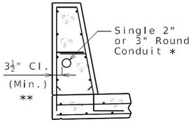
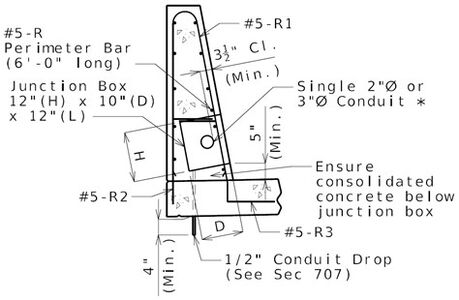
For single conduit placement, 3-inch round conduit is the maximum size preferred and shall be placed in the barrier. | For single conduit placement, 3-inch round conduit is the maximum size preferred and shall be placed in the barrier. | ||
:Single 4-inch round conduit may be used based on core team agreement that single 4-inch round conduit is absolutely required to meet the project need. Single 4-inch round conduit shall be placed in the barrier . (Practical difficulties in placing single 4-inch round conduit in the barrier could include sweeping from the outside face to the roadway face for junction box connections, increased interference with reinforcement, and less assurance for consolidated concrete under the conduit.) | :Single 4-inch round conduit may be used based on core team agreement that single 4-inch round conduit is absolutely required to meet the project need. Single 4-inch round conduit shall be placed in the barrier. (Practical difficulties in placing single 4-inch round conduit in the barrier could include sweeping from the outside face to the roadway face for junction box connections, increased interference with reinforcement, and less assurance for consolidated concrete under the conduit.) | ||
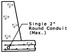
:Single 2-inch round conduit may be placed in the slab when necessary, for example, when using barrier, either concrete or steel, that cannot accept conduit, or when surplus conduit must be run and placement in the barrier has been exhausted. Minimum clearance may be less than 3 inches. | :Single 2-inch round conduit may be placed in the slab when necessary, for example, when using barrier, either concrete or steel, that cannot accept conduit, or when surplus conduit must be run and placement in the barrier has been exhausted. Minimum clearance may be less than 3 inches. | ||
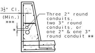
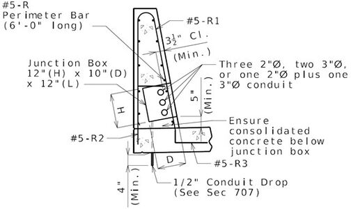
For multiple conduit placement, | For multiple conduit placement, three 2-inch round conduits, two 3-inch round conduits, or 2-inch plus 3-inch round conduit in combination may be used and shall be placed in the barrier. | ||
:4-inch round conduit shall not be combined with 2-inch round conduit or 3-inch round conduit where multiple conduits are to be placed in the barrier. | :4-inch round conduit shall not be combined with 2-inch round conduit or 3-inch round conduit where multiple conduits are to be placed in the barrier. | ||
:Minimum clearance | :Minimum clearance between conduits placed in the barrier shall be one inch. | ||
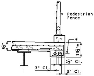
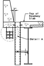
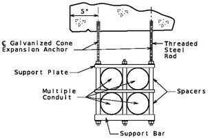
:Placement method of multiple conduits shall be determined on a case-by-case basis. Other options include placing conduits on hangers or placing conduits in a deepened slab. Hangers and supports may be designed in accordance to a manufacturer’s specifications or they can be designed by a manufacturer for all external and internal loads. This depends on the number of conduits to be supported by hangers and the complexity of the design. Supporting connections like concrete anchors into the bridge must also be designed. Spacing of hangers may be made by the manufacturer and if necessary as shown on the plans. Resin anchors are not allowed for overhead installations. Special provisions may be required to instruct the contractor for this work. | :Placement method of multiple conduits shall be determined on a case-by-case basis. Other options include placing conduits on hangers or placing conduits in a deepened slab. Hangers and supports may be designed in accordance to a manufacturer’s specifications or they can be designed by a manufacturer for all external and internal loads. This depends on the number of conduits to be supported by hangers and the complexity of the design. Supporting connections like concrete anchors into the bridge must also be designed. Spacing of hangers may be made by the manufacturer and if necessary as shown on the plans. Resin anchors are not allowed for overhead installations. Special provisions may be required to instruct the contractor for this work. | ||
| Line 1,870: | Line 1,849: | ||
'''Conduit Systems Placement''' | {| cellpadding=10 | ||
|- | |||
| || <center>'''Conduit Systems Placement'''</center> || | |||
|- | |||
| [[image:751.10.4-Single_Conduit_in_Slab-Feb-23.jpg|center|x175px]] | |||
| [[image:751.10.4-Single_Conduit_in_Barrier-Feb-23.jpg|center|x175px]] | |||
| [[image:751.10.4-Multiple_Conduits_in_Safety_Barrier-Feb-23.jpg|center|x175px]] | |||
|- style="text-align: center; vertical-align: top;" | |||
| <b>Section of Single Conduit in Slab</b> | |||
| <b>Section Showing Single Conduit in Barrier</b> | |||
| <b>Section of Multiple Conduits in Safety Barrier Curb</b> | |||
|- style="vertical-align: top;" | |||
| | |||
| * Single 4-inch round conduit if absolutely required</br>to meet the project need and based on core team agreement.</br>** 3 ½-inch clear provides approximately 1” clearance</br>between the conduit and vertical reinforcing steel. | |||
| * One-inch minimum.</br>** Single four-inch round conduit if absolutely</br>required to meet the project need and based on</br>core team agreement.</br>*** 3 ½-inch clear provides approximately 1”</br>clearance between the conduit and vertical</br>reinforcing steel. | |||
|- | |||
| | |||
|- | |- | ||
|[[image:751.10.4 | | [[image:751.10.4-Multiple_Conduits_in_Deepened_Slab-Feb-23.jpg|center|x250px]] | ||
| | | [[image:751.10.4-Section_Suspended_Conduit-Feb-23.jpg|center|x250px]] | ||
| [[image:751.10.4-Section_Suspended_Conduit_DetailA-Feb-23.jpg|center|x200px]] | |||
|- style="text-align: center; vertical-align: top;" | |||
| <b>Section of Multiple Conduits in Deepened Slab</b> | |||
| <b>Part Section of Suspended Conduit (on Hanger) at Drain</b> | |||
| <b>Detail A (Hanger)</b> | |||
|- style="vertical-align: top;" | |||
| * Permissible combination may include 4-inch round</br>conduit. More than two conduits may be used. | |||
| | |||
| | |||
|- | |- | ||
|} | |} | ||
'''Expansion Fittings and Setting''' | '''Expansion Fittings and Setting''' | ||
| Line 1,920: | Line 1,914: | ||
:Expansion fittings shall be placed and set in accordance with the manufacturer’s requirements based on the air temperature at the time of setting given an estimated total conduit expansion movement using a maximum temperature range of 120°F and a maximum temperature of 110°F. For conduit exposed to direct sunlight, 30°F is added typically to the temperature range for design purposes only. | :Expansion fittings shall be placed and set in accordance with the manufacturer’s requirements based on the air temperature at the time of setting given an estimated total conduit expansion movement using a maximum temperature range of 120°F and a maximum temperature of 110°F. For conduit exposed to direct sunlight, 30°F is added typically to the temperature range for design purposes only. | ||
:Nonmetallic conduit clamps shall be specified to allow the conduit to move freely during expansion and contraction while properly securing it. Expansion fitting barrels should be clamped securely whereas conduit should be mounted loosely so that it can slide freely | :Nonmetallic conduit clamps shall be specified to allow the conduit to move freely during expansion and contraction while properly securing it. Expansion fitting barrels should be clamped securely whereas conduit should be mounted loosely so that it can slide freely. | ||
| Line 1,970: | Line 1,964: | ||
'''Junction Boxes and Placement''' | '''Junction Boxes and Placement''' | ||
| Line 1,990: | Line 1,983: | ||
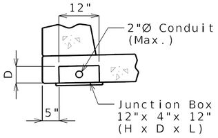
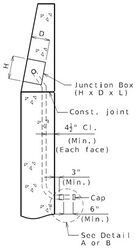
When 2-inch round conduit is placed in the slab, preferred placement of junction boxes shall be in the slab and in areas accessible from underneath the bridge. | When 2-inch round conduit is placed in the slab, preferred placement of junction boxes shall be in the slab and in areas accessible from underneath the bridge. | ||
{| border="1" class="wikitable" style="margin: 1em auto 1em auto" align="center" style="text-align:center" | {| border="1" class="wikitable" style="margin: 1em auto 1em auto" align="center" style="text-align:center" | ||
| Line 1,996: | Line 1,988: | ||
! colspan="3" style="background:#BEBEBE"|Junction Box Size Requirements | ! colspan="3" style="background:#BEBEBE"|Junction Box Size Requirements | ||
|- | |- | ||
!rowspan="2" style="background:#BEBEBE"|Junction Box Placement!!rowspan="2" style="background:#BEBEBE" |Conduit | !rowspan="2" style="background:#BEBEBE"|Junction Box Placement!!rowspan="2" style="background:#BEBEBE" |Entering Conduit Size(s) !! style="background:#BEBEBE"|Junction Box Size<sup>1</sup> | ||
|- | |- | ||
! style="background:#BEBEBE"|H x D x L<sup>2</sup>, inches | ! style="background:#BEBEBE"|H x D x L<sup>2</sup>, inches | ||
|- | |- | ||
|rowspan=" | |rowspan="6"|Concrete Barrier Type D</br>Or</br>Type H</br>Or</br>Abutment Wing || Single 2” Round Conduit || rowspan="6" | 12 x 10 x 12 | ||
|- | |- | ||
|Single 3” Round Conduit | |Single 3” Round Conduit | ||
|- | |- | ||
|Single | |Single 4” Round Conduit<sup>'''3'''</sup> | ||
|- | |- | ||
| | |Three 2” Round Conduit | ||
|- | |- | ||
|Two 3” Round Conduit | |Two 3” Round Conduit | ||
| Line 2,016: | Line 2,004: | ||
|2” plus 3” Round Conduit | |2” plus 3” Round Conduit | ||
|- | |- | ||
|Slab|| 2” Round Conduit|| 4 | | 8 1/2 inch Slab || 2” Round Conduit || 12 x 4 x 12 | ||
|- | |- | ||
|colspan="3" align=left|<sup>'''1'''</sup> Note on the plan that Junction box size shown on plan may require special order. | |colspan="3" align=left|<sup>'''1'''</sup> Note on the plan that Junction box size shown on plan may require special order. Smaller junction box may be substituted if junction box meets conduit installation, clearance and project requirements. | ||
|- | |- | ||
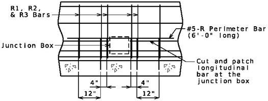
|colspan="3" align=left|<sup>'''2'''</sup> Length may be increased, if required. Coordinate with core team or district traffic. | |colspan="3" align=left|<sup>'''2'''</sup> Length may be increased, if required. Coordinate with core team or district traffic. For junction box longer than 12”, an additional transverse bar pair should be spaced at 4 inch in addition to shown transverse bar pairs in “Part Elevation of Barrier over Slab Showing Perimeter Steel” on both sides of junction box. | ||
|- | |- | ||
|colspan="3" align=left|<sup>'''3'''</sup> | |colspan="3" align=left|<sup>'''3'''</sup> Single 4-inch round conduit may be used based on core team agreement that single 4-inch round conduit is absolutely required to meet the project need. Single 4-inch round conduit shall be placed in the barrier and abutment wing. | ||
|} | |} | ||
[[image:751.10.4 | <center>'''Details of Junction Box Placements'''</center> | ||
{| cellpadding=2 style="margin-left: auto; margin-right: auto;" | |||
|- | |||
| [[image:751.10.4-Junction_Box-Feb-23.jpg|center|x200px]] | |||
| [[image:751.10.4-Barrier_Curb-Feb-23.jpg|center|x225px]] | |||
|- style="text-align: center; vertical-align: top;" | |||
| <b>Section of Junction Box in Slab</b> | |||
| <b>Part Plan of Barrier Showing Delineated Conduit System Placement Only</b><center>(Use where junction boxes are in wing only)</center>Single conduit shown, multiple conduits similar.</br>Expansion fittings or deflection couplings are not shown for clarity.</br>Drawing is not to scale.</br> | |||
|- | |||
|} | |||
<center>Select Detail A or B based on total movement and show on plan.</center> | {| cellpadding=2 style="margin-left: auto; margin-right: auto;" | ||
|- | |||
| colspan=2 | <b><center>Select Detail A or B based on total movement and show on plan.</center></b> | |||
|- | |||
| [[image:751.10.4-Barrier_Curb_Detail_A-Feb-23.jpg|center|x250px]] | |||
| [[image:751.10.4-Barrier_Curb_Detail_B-Feb-23.jpg|center|x250px]] | |||
|- style="text-align: center; vertical-align: top;" | |||
| <b>Detail A</b> | |||
| <b>Detail B</b> | |||
|- style="text-align: center; vertical-align: top;" | |||
| (Use where total movement is not greater than 1½ inches.) | |||
| (Use where total movement is greater than 1½ inches.) | |||
|} | |||
[[image:751.10.4 | {| cellpadding=2 style="margin-left: auto; margin-right: auto;" | ||
|- | |||
| [[image:751.10.4-Junction_Box_in_Wing-Feb-23.jpg|center|x300px]] | |||
| [[image:751.10.4-Wing_Section_AA-Feb-23.jpg|center|x250px]] | |||
|- style="text-align: center; vertical-align: top;" | |||
| <b>Part Elevation Showing Junction Box in Wing</b> | |||
| <b>Section A-A</b> | |||
|- style="text-align: center; vertical-align: top;" | |||
| (Use where junction box is in wing only)<br>(Single conduit shown, multiple conduits similar.) | |||
| (Single conduit shown, multiple conduits similar.) | |||
|} | |||
[[image:751.10.4 | {| cellpadding=2 style="margin-left: auto; margin-right: auto;" | ||
<center | |- | ||
| [[image:751.10.4-Junction_Box_in_Barrier-Feb-23.jpg|center|x300px]]<center>'''*''' Minimize length of sweep in order to lessen the number of #5-R1 bars necessary to bend in field.</center> | |||
| [[image:751.10.4-Barrier_Curb_Section_BB-Feb-23.jpg|center|x250px]] | |||
|- style="text-align: center; vertical-align: top;" | |||
| <b>Part Plan of Barrier Showing Delineated Conduit System Placement Only</b> | |||
| <b>Section B-B</b> | |||
|- style="text-align: center; vertical-align: top;" | |||
| (Use where junction boxes are in barrier only.)</br>Single conduit shown, multiple conduits similar.</br>Expansion fittings or deflection couplings are not shown for clarity.</br>Drawing is not to scale. | |||
| (Single conduit shown, multiple conduits similar.) | |||
|} | |||
[[image:751.10.4 | {| cellpadding=2 style="margin-left: auto; margin-right: auto;" | ||
< | |- | ||
| [[image:751.10.4-Barrier_Curb_over_Slab-Feb-23.jpg|center|x200px]] | |||
|- style="text-align: center; vertical-align: top;" | |||
| <b>Part Elevation of Barrier over Slab Showing Perimeter Steel</b> | |||
|- style="text-align: center; vertical-align: top;" | |||
| (Use where junction boxes are in barrier only.)</br>Show extra R1, R2, R3 and #5-R Perimeter Bar 6’-0” long with the barrier details and include in the Bill of Reinforcing Steel.</br>Perimeter bar (#5-R) is not required at end bent junction boxes. Spacing of K bars is more condensed at end bents. Extra K bars may be used and shown with the barrier details and included in the Bill of Reinforcing Steel. | |||
|} | |||
<center> | {| cellpadding=2 style="margin-left: auto; margin-right: auto;" | ||
|- | |||
| [[image:751.10.4-Barrier_Curb_Section_Single_Conduit-Feb-23.jpg|center|x300px]]<center>* Single 4-inch round conduit if absolutely required.</center> | |||
| [[image:751.10.4-Barrier_Curb_Section_Multiple_Conduit-Feb-23.jpg|center|x300px]] | |||
|- style="text-align: center; vertical-align: top;" | |||
| <b>Section through Barrier Showing Junction Box</b> | |||
| <b>Section through Barrier Showing Junction Box</b> | |||
|- style="text-align: center; vertical-align: top;" | |||
| (Single Conduit near Roadway Face) | |||
| (Multiple Conduits near Roadway Face) | |||
|- | |||
|} | |||
{| cellpadding=2 style="margin-left: auto; margin-right: auto;" | |||
|- | |||
| <b>Note: 3½” inch clear provides approximately 1½” clearance between the conduit and vertical</br>reinforcing steel on roadway face. This clearance is excessive, but is recommended</br>to keep the clearances to front and back face of barrier similar for ease of construction.</b> | |||
|- | |||
|} | |||
==751.10.5 Approach Slab== | ==751.10.5 Approach Slab== | ||
Latest revision as of 14:54, 10 October 2024
Regardless of type of barrier or railing shown the following guidance is applicable for all barrier and railing types.
751.10.1 Slab on Girder
751.10.1.1 Material Properties
| Concrete Slab on Girders | ||
|---|---|---|
| Unit weight of reinforced concrete, | = 150 | |
| Class B-2 Concrete | = 4.0 ksi | |
| = 8 | ||
| Modulus of elasticity, | ||
| Where: | ||
| f'c in ksi | ||
| = unit weight of nonreinforced concrete = 0.145 kcf | ||
| K1 = correction factor for source of aggregate aa = 1.0 unless determined by physical testing | ||
| Modulus of rupture: | = 0.24 LRFD 5.4.2.6 | |
| Where: | ||
| f'c in ksi | ||
| Concrete Barrier or Railing | ||
| Class B-1 Concrete | = 4.0 ksi | |
| = 8 | ||
| Future Wearing Surface | ||
| Unit weight of future wearing surface, | = 140 | |
| Reinforcing steel | ||
| Minimum yield strength, | = 60.0 ksi | |
| Steel modulus of elasticity | = 29000 ksi | |
751.10.1.2 Limit States and Load Factors
In general, each component shall satisfy the following equation:
Where:
| = Total factored force effect | |
| = Force effect | |
| = Load modifier | |
| = Load factor | |
| = Resistance factor | |
| = Nominal resistance | |
| = Factored resistance |
Limit States
The following limit states shall be considered for slab interior and overhang design:
| For slab interior design: | STRENGTH – I SERVICE – I* |
| For slab overhang design: | EXTREME EVENT – II STRENGTH – I SERVICE – I* |
| *Of deformation, cracking, and concrete stresses, only cracking need be considered here. | |
| FATIGUE limit state need not be investigated for concrete decks in multi-girder bridges due to observed performance and laboratory testing. | |
Resistance factors
For STRENGTH limit state,
- Flexure and tension of reinforced concrete, = 0.90
- Shear and torsion, = 0.90
For all other limit states, = 1.00
751.10.1.3 Loads
Permanent (Dead) Loads
Permanent loads include the following:
- Slab weight
- Future Wearing Surface
- A 3-inch thick future wearing surface (35psf) shall be considered on the roadway.
- Barrier or Railing
- For slab overhang design, assume the weight of the barrier or railing acts at the centroid of the barrier or railing.
- Gravity Live Loads
- Gravity live loads include vehicular, dynamic load allowance, and pedestrian loads. See EPG 751.2.2.1 Live Load Figure 2 for General Application of Live Loads to Bridge Deck.
- Vehicular
- The design vehicular live load HL-93 shall be used. It consists of either the design truck or a combination of design truck and design lane load.
- For slab design, where the approximate strip method is used, the force effects shall be determined based on the following:
- Where the slab spans primarily in the transverse direction, the design shall be based on axle loads of the design truck alone.
Dynamic Load Allowance
The dynamic load allowance replaces the effect of impact used in AASHTO Standard Specifications. It accounts for wheel load impact from moving vehicles. For slabs, the static effect of the vehicle live load shall be increased by the percentage specified in Table below.
| Slab Component | IM |
|---|---|
| Deck Joints – All Limit States | 75% |
| All Other Limit States | 33% |
The factor to be applied to the static load shall be taken as:
The dynamic load allowance is not to be applied to pedestrian or design lane loads.
Multiple Presence Factor, m:
The multiple presence factor accounts for the probability for multiple trucks passing over a multilane bridge simultaneously.
| m = | 1.20 for 1 Loaded Lane |
| 1.00 for 2 Loaded Lanes | |
| 0.85 for 3 Loaded Lanes | |
| 0.65 for greater than 3 Loaded Lanes |
Pedestrian
Pedestrian live load on sidewalks greater than 2 ft wide shall be:
| PL = | 0.075 ksf |
This does not include bridges designed exclusively for pedestrians or bicycles.
Collision Loads
Collision loads applied to the barrier shall be transferred to the slab overhang. The design forces from barrier consist of lateral and vertical components that are to be considered separately. Because of MoDOT’s experience with the collision survivability of bridge decks that utilize the standard concrete barriers, MoDOT does not require the deck overhang to be designed for forces in excess of those resulting from the design loads for Traffic Railings shown in LRFD Table A13.2-1. The standard slab cross sections reflect this design philosophy.
LRFD Table A13.2-1 (2020 specifications) is not up-to-date with the latest MASH 2016 criteria. NCHRP Project 20-7, Task 395 (TTI Project 607141), MASH Equivalency of NCHRP Report 350-Approved Bridge Railings released the following table of updated loads. This table may not reflect completely the values that will get implemented in the AASHTO LRFD Bridge Design Specifications. For example, further testing has shown that the Rail Height, H, for TL-3 may be 30 inches. There is also ongoing research that will effectively increase the capacity of overhangs in collision events.
| MASH 2016 Collision Loads for Barrier Design | |||||
|---|---|---|---|---|---|
| Design Forces and Designations |
TL-3 | TL-4 1 |
TL-4 2 |
TL-5 1 |
TL-5 2 |
| Rail Height, H (in.) | 32 | 36 | ≥36 | 42 | >42 |
| Ft Transverse (kips) | 70 | 70 | 80 | 160 | 260 |
| FL Longitudinal (kips) | 18 | 22 | 28 | 75 | 75 |
| Fv Vertical (kips) | 4.5 | 38 | 33 | 160 | 80 |
| LL (ft.) | 4 | 4 | 5 | 10 | 10 |
| Lv (ft.) | 18 | 18 | 18 | 40 | 40 |
| He (in.) | 24 | 25 | 30 | 34 | 43 |
Until both the new loads and new resistances are implemented in LRFD, the standard top transverse reinforcement scheme shown in EPG 751.10.1.7 Standard Bridge Deck Details is considered adequate for collision loads in new bridge decks. The top transverse reinforcement scheme is also considered adequate for collision loads for redecks where the effective depth to the top transverse bar is not less than 4 3/8 inches.
- Design Case 1
- The collision force and moment shall be considered.
- Slab Overhang Design Collision Moment
- The design collision moment at the base of the barrier is the barrier moment capacity about the barrier longitudinal axis. The partial development of the reinforcing bars should be considered in determining this moment capacity.
- at base
- Slab Overhang Design Collision Force
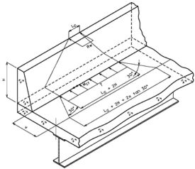
- A refined analysis may be performed. In this case the design collision moment at the base of the barrier, Mct, is to be taken as the average moment over the theoretical distribution length (Lc+2H for continuous sections), when the TL collision load is applied to the top of the barrier.
- For continuous sections of barrier:
- Where:
= total transverse resistance of barrier not to exceed the transverse collision force, Ft, for the required test level = critical length of yield line failure pattern = height of barrier = tensile force per unit of deck length at base of barrier
- For discontinuous barrier sections:
| Collision Properties for Concrete Barriers (MASH 2016) | ||||
|---|---|---|---|---|
| Location | Type D | Type H | ||
| Continuous | End | Continuous | End | |
| Test Level | TL-4 | TL-4 | TL-3 | TL-3 |
| Rw (k) | 1521 | 821 | 1451 | 811 |
| Ft (k) | 80 | 80 | 70 | 70 |
| Lc (ft) | 14.16 | 7.24 | 11.23 | 5.76 |
| H (in) | 42 | 42 | 32 | 32 |
| Mct (k-ft) | 11.72 | 11.72 | 11.72 | 11.72 |
| T (k/ft) | 3.78 | 7.45 | 4.23 | 8.31 |
| 1 Values provided by MwRSF, see Mash Equivalency of MoDOT Type D Barrier, 2019, Rosenbaugh. MwRSF uses the fully developed Mc at the base, and also applies a resistance factor of 0.9 in the calculation of Rw. The Lc values provided are calculated using an average moment capacity, Mc, about the longitudinal axis over the height of the barrier. Partial development of reinforcing steel is ignored. All moment capacities assume doubly reinforced sections. | ||||
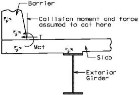
Transfer of Barrier Collision Forces
751.10.1.4 Design and Analysis Methods
Equivalent Strip Method
The equivalent strip method is an approximate method of analysis in which the reinforcing steel is designed using a certain width of deck to resist the applied loading. Where the strip method is used, the extreme positive moment in any slab section between girders shall be taken to apply to all positive moment regions, and similarly with extreme negative moments.
There are other methods of analysis allowed, such as finite element method, but the equivalent strip method is recommended.
751.10.1.5 Interior Section Design
Slab Thickness
For multi-span bridges the slab portion between girders shall be 8 1/2” thick for both the full depth cast-in-place concrete and partial depth precast prestressed concrete panel standard slabs. For new single-span bridges the slab thickness may be reduced to 8 inches for full depth cast-in-place decks. A minimum 5 1/2-inch cast-in place topping is required when precast panels are used.
Design Cases
Two design cases shall be considered for each design condition.
Design Case 1 STRENGTH I load combination for reinforcing design.
Design Case 2 SERVICE I load combination for cracking check.
Design Conditions
Two design conditions can exist for the slab interior.
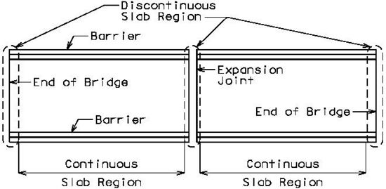
Design Condition 1 – Continuous slab, where the slab section under consideration is not near an end bent or expansion joint.
Design Condition 2 – Discontinuous slab, where the slab section under consideration is at an end bent or expansion joint.
Critical Sections
The critical design section for negative moments may be taken as follows:
| For steel girders - | the design negative moment should be taken at 1/4 of the flange width from the centerline of the web. |
| For prestressed I girders - | the design negative moment should be taken at 1/3 of the flange width, but not exceeding 15 inches from the centerline of the web |
The critical design slab section for positive moment shall be taken at location of maximum positive moment – generally midway between girders.
Width of Equivalent Strip at Continuous Slab Section
| For Positive Moment | |
| For Negative Moment |
Where:
| = equivalent strip width (inches) | |
| = spacing of centerline to centerline of supporting components (feet) |
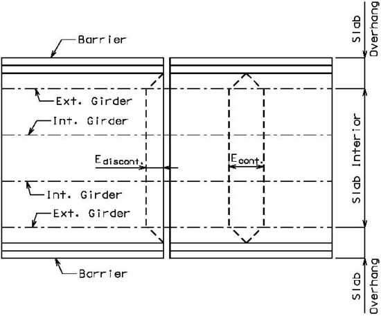
Width of Equivalent Strip at Discontinuous Slab Section
The effective strip width shall be taken as ½ of the equivalent strip width for a continuous slab section plus the distance between the transverse edge of slab and the edge beam (if any).
Determining Live Load
Slab interior live load design moments may be determined using Appendix Table A4-1 of the LRFD Specifications, provided that the assumptions used in the table are appropriate. It is assumed that the table is only applicable to continuous sections of slab (not at joints). It may be used at discontinuous sections by adjusting the tabulated moments as follows:
Where:
| = equivalent strip width (in). | |
| = vehicular dynamic load allowance. |
Note: includes multiple presence factor, .
Alternatively, the designer may use other sources to determine the design moments. For example any capable computer program for finite element design may be used.
The general methodology for applying live load to slab on girder with transverse primary strips is:
- Model the bridge cross section.
- Define the design vehicle (design truck).
- Move the design vehicle between the barrier and add additional design vehicles as required to produce the maximum force effect. The wheel load shall not be closer than 1 ft. to the face of barrier and wheel loads of adjacent design vehicles shall not be closer than 4 ft. The design lane is assumed to occupy a 10 ft. width. Partial trucks (i.e. one wheel) should not be used.
Determining Dead Load
For slab analysis assume that slab is full depth cast-in-place (CIP). The maximum negative and positive dead load moment may be taken to be:
Continuous over 4 girders (equally spaced):
Continuous over 5 girders (equally spaced):
Where:
| = moment at centerline of exterior girder due to: slab, future wearing surface, barrier, sidewalk, and other dead load components | |
| = center-to-center girder spacing |
Determining Top Reinforcing
The top (negative) reinforcing steel may be determined by assuming the section to be either singly- or doubly-reinforced, as needed.
Determining Bottom Reinforcing
The bottom (positive) reinforcing steel may be determined by assuming the section to be either singly- or doubly-reinforced, as needed. A 1” wearing surface shall be removed from the effective depth, .
Minimum Tensile of Reinforcement
The amount of tensile reinforcement shall be adequate to develop a factored flexural resistance, , at least equal to the lesser of either:
- 1) Mcr = cracking moment LRFD Eq. 5.7.3.3.2-1
- 2) 1.33 times the factored moment required by the applicable strength load combinations specified in LRFD Table 3.4.1-1.
Shrinkage and Temperature Reinforcement
The area of reinforcing for top longitudinal steel, As, shall not be less than As computed in accordance with LRFD 5.10.8:
- Maximum spacing of longitudinal reinforcement = min
- 5 @ 15” are shown for standard slabs.
Distribution Reinforcement
The bottom longitudinal steel, as a percentage of the bottom primary reinforcement, shall not be less than:
Where:
| = effective span length (ft) specified in LRFD 9.7.2.3. It is the distance between flange tips, plus the flange overhang, taken as the distance from extreme flange tip to the face of the web. |

Concrete Cover
The cover requirements that follow meet or exceed LRFD requirements.
At Bottom of CIP slabs 1.00 inch Bottom of CIP slab over P/C P/S panels 1.00 inch Top reinforcing (multi-span bridges) 3 inches preferred, 2 3/4 inches absolute Top reinforcing (single span bridges) 3 inches preferred
For new single span bridges with full depth cast-in-place decks that utilize an 8-inch slab thickness, the clear cover to the top longitudinal reinforcing shall be 2 5/8 inches.
For redecks where the slab thickness is required to be less than 8 1/2 inches due to grade restrictions, the absolute min to the top reinforcing steel is 2 inches.
Spacing Limits
LRFD 5.10.3.1.1 Minimum clear spacing between parallel bars in a layer:
| Maximum of: | 1) 1.5 where is bar diameter (in) |
| 2) 1.5 times maximum aggregate size (*) | |
| 3) 1.5 in |
(*) see Missouri Standard Specifications for Highway Construction
Bar Development
The calculated force effects in reinforcement shall be developed on each side of the critical section.
Cracking Check
Actual Stress
A transformed cracked section analysis shall be used with SERVICE-I moments to determine actual stress in reinforcing.
The spacing of mild steel reinforcement in the layer closest to the tension face shall satisfy the following:
in which:
Where:
| = exposure factor | |
| = .75 for class 2 exposure condition. | |
| = actual thickness of concrete cover measured from extreme tension fiber to center of the flexural reinforcement located closest thereto (in) | |
| = tensile stress in steel reinforcement at the service limit state (ksi) |
Reinforcing Placement
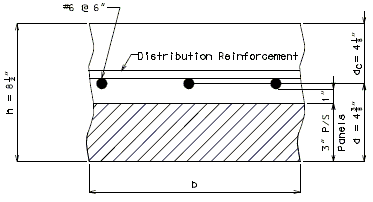
Although LRFD Specifications allow slab primary reinforcing to be skewed with the bridge under certain cases, MoDOT Bridge practice is to place transverse reinforcing perpendicular to roadway
Note: Due to the depth of cover and location of primary reinforcement, the cracking check shown on the previous page does not appear to be accurate for Missouri’s bridge decks shown above.
Negative Moment Steel over Intermediate Supports
Dimension negative moment steel over intermediate supports as shown.
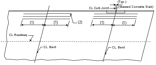
| (1) | Bar length by design | |
| (2) | Reinforcement placed between longitudinal temperature reinforcing in top. | |
| Bar size: | #5 bars at 7 1/2" cts. (Min.) | |
| #8 bars at 5" cts. (Max.) | ||
Steel Structures:
| (1) | Extend into positive moment region beyond "Anchor" Stud shear connectors at least 40 x bar diameter x 1.5 (Epoxy Coated Factor) (*) as shown below. |
| (2) | Use #6 bars at 5-inch centers between longitudinal temperature reinforcing in top. |

Locations of termination of reinforcement steel in the deck slab for Prestressed Structures shall be checked for the following criteria and adjusted as necessary:
- No greater than 50 percent of the bar count shall be terminated at any section.
- Adjacent bars shall not be terminated in the same section.
- Flexural reinforcement shall be extended beyond the point at which it is no longer required to resist flexure for a distance not less than:
- The effective depth of the member
- 15 times the nominal diameter of bar
- 1/20 of the clear span (centerline to centerline of pier)
- Continuing reinforcement shall extend not less than the development length, ld, beyond the point where reinforcement is no longer required to resist flexure.
- At least one third of the total tension reinforcement provided for negative moment at a support shall have an embedment length beyond the point of inflection not less than:
- The effective depth of the member
- 12 times the nominal diameter of bar
- 0.0625 times the clear span (centerline to centerline of pier)
751.10.1.6 Slab Overhang Section Design
Girder Layout
In order to use distribution factors provided in LRFD Table 4.6.2.2.2 for girder design, the roadway overhang shall not exceed 5.5 feet.
Slab Thickness
For new multi-span bridges the overhang slab thickness shall be 8½ inches. For new single span bridges the overhang slab thickness shall match the depth used between girders.
Design Cases
Four design cases shall be considered for each design condition.
| Design Case 1 | EXTREME EVENT II load combination with transverse and longitudinal collision force components |
| Design Case 2 | EXTREME EVENT II load combination with vertical collision force components (Does not control slab for TL-4). |
| Design Case 3 | STRENGTH I load combination |
| Design Case 4 | SERVICE I load combination for cracking check |
Design Conditions
Three design conditions may exist for slab overhang design.
| Design Condition 1 – | Continuous Slab & Continuous Barrier |
| Design Condition 2 – | Continuous Slab & Discontinuous Barrier |
| Design Condition 3 – | Discontinuous Slab & Discontinuous Barrier |
Critical Sections
The critical design section for slab overhang shall be at the following two locations:
- At roadway face of barrier
- At exterior girder:
- For steel girders – the design negative moment should be taken at ¼ of the flange width from the centerline of the web.
- For P/S-I girders - the design negative moment should be taken at 1/3 of the flange width, but not exceeding 15” from the centerline of the web.
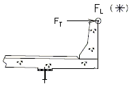
|

|
| Barrier Loading | Slab Design Loading |
| DESIGN CASE 1 | |
|---|---|
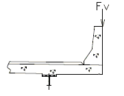
| |
| DESIGN CASE 2 | |
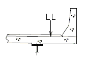
| |
| LL = vehicular live load | |
| DESIGN CASE 3 | |
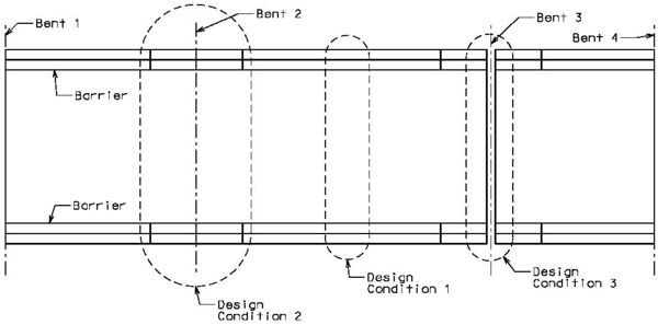
Width of Equivalent Strip at Continuous Slab Section
The equivalent strip width for a continuous section of slab overhang shall be:
Where:
| = equivalent width (in) | |
| = distance from load to point of support (ft) |
Width of Equivalent Strip at Discontinuous Slab Section
LRFD 4.6.2.1.4c The effective strip width shall be taken as 1/2 of the equivalent strip width for a continuous slab section plus the distance between the transverse edge of slab and the edge beam (if any). This shall not be taken to be greater than equivalent strip width for continuous slab section.
Assumed Load Distribution
To determine the load effect at slab overhang critical sections, the slab shall be assumed as fixed at the exterior girder. This assumption is intended for slab design only, not the distribution of slab loads to girder.
For the purpose of determining the collision load effect at slab critical sections, the load may be assumed to fan out at 30 degrees on each side from the point of load.
Determining Top Reinforcing
The top (negative) reinforcing steel may be determined by assuming the section to be either singly or doubly reinforced, as needed. For slab overhang lengths equal to or less than 3’-10”, the reinforcement shown in the standard slab details is adequate (see EPG 751.10.1.7). For overhang lengths greater than 3’-10”, further analysis is required for top transverse steel design.
Effect of Slab Drains
The effect of slab drain openings in the slab overhang shall be considered. Their effect may be considered by ensuring the following:
Where:
| = area of steel provided over the strip width including effect of drain openings | |
| = area of steel required over strip width by calculation |
Reinforcing Criteria
Reinforcing limits, cover, temperature steel, distribution steel, and placement shall be the same as for Slab Interior Section.
Special Considerations for Light Poles
Standard details for mounting 30-foot and 45-foot Type B light poles on concrete barrier are provided. At the barrier-to-slab interface, the force effect of wind on the light pole (STRENGTH - III) with 90 mph wind is less than that due to EXTREME EVENT-II (TL-4) on concrete barrier. Therefore, reinforcing designed for EXTREME EVENT-II (TL-4) load combination will be adequate.
751.10.1.7 Standard Bridge Deck Details
Show following detail with standard details. Nonstandard details should account for top longitudinal slab bar placement for tying R3 and R4 barrier bars.
Guidance Note for Detailing: Indicate only the top longitudinal slab bars affected for tying the R4 barrier bar. It may be that only one bar needs to be indicated for shifting.
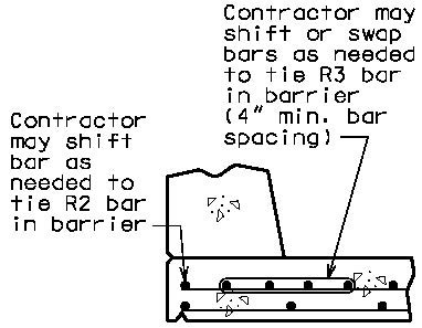
|
751.10.1.7.1 Standard Full Depth CIP Bridge Deck Slabs Using Conventional Forms, SIP Corrugated Steel Forms, or SIP Transparent Forms
| (A) | Full depth CIP (cast-in-place) slab cross sections with reinforcement designed for the HL-93 live load are shown for nine standard roadway widths. |
| (B) | Slab design includes an allowance for 35 psf future wearing surface. |
| (C) | Slab design is based on ultimate strength design, f’c equals 4 ksi, and Grade 60 reinforcing steel. |
| (D) | When the flange width exceeds the bottom longitudinal reinforcement spacing over the girder, reduce the bar spacing between the girders and increase the bar spacing over the girder to clear the flange edges. |
| (E) | When the structure is on grade, determine lengths of the longitudinal reinforcement in the slab and barrier from the actual length. |
| (F) | For slab design, the centerline of wheels is located one foot from face of barrier or curbs. |
| (G) | Standard slabs were designed assuming 12-inch minimum flanges and are applicable for plate girders, wide flange beams, MoDOT prestressed girders, and NU and bulb-tee girders when slab drains are not required or slab cantilevers that are less than 44 inches in the case of bulb-tee girders. |
| (H) | The bridge roadway width, from gutter line to gutter line, shall be the same as the roadway width (from outside edge of shoulder to outside edge of shoulder). |
| (I) | Standard slab designs do not include the effect of features not shown (i.e. sidewalk, fence, utilities, etc…) except for future wearing surface. |
| (J) | Guidance for minimum concrete cover for top slab bars is 3 inches and shall meet EPG 751.5.9.2 Reinforcing Steel. This cover is required for #6 top slab bars used in tandem. An exception is made for larger top slab bars, e.g. #8 longitudinal bars where cover will need to be reduced to 2 3/4 inches. |
| (K) | The standard slab reinforcement shown in this article for HL-93 live load were designed using dead loads given in EPG 751.10.2.3 for stay-in-place corrugated steel forms and EPG 751.10.2.4 for stay-in-place transparent forms. |
Generally, when the deck is bid in square yards, barrier is bid in linear feet, and when the deck is bid in cubic yards, barrier is bid in cubic yards.
751.10.1.7.2 Standard Partial Depth Precast Prestressed Panel Bridge Deck Slabs Using SIP P/C P/S Panel Forms
| (A) | Precast prestressed panel bridge deck cross sections are not shown. A partial depth cast-in-place deck shall consist of three-inch precast prestressed panel forms with a 5 1/2-inch minimum cast-in-place concrete topping. For details, use standard full depth CIP deck cross sections and top deck reinforcement only replacing the bottom layer of reinforcement between the girders with panels. For nonstandard roadway cross sections, the deck slab is designed like a full depth CIP deck slab and detailed as before for standard roadway cross sections within the limits of panel width given in EPG 751.10.2.1 Precast Prestressed Concrete Panel Forms - Design. Cantilever reinforcement details for partial depth P/C P/S panel deck slabs are shown below. |
| (B) | Slab design includes an allowance for 35 psf future wearing surface. |
| (C) | Slab design is based on ultimate strength design, f’c equals 4 ksi and grade 60 reinforcing steel for cast-in-place concrete and EPG 751.10.2.1 for precast prestressed panel form design. |
| (D) | Haunching diagrams shall be provided for only the precast prestressed panel deck slab. Quantities for slab haunching may be estimated by taking 4% of slab quantities for steel structures and 2% for prestressed structures. More exact methods are recommended. |
| (E) | When the structure is on grade, determine lengths of the longitudinal reinforcement in the slab and barrier from the actual length. |
| (F) | For slab design, the centerline of wheels is located one foot from face of barrier or curbs. |
| (G) | Standard slabs were designed assuming 12-inch minimum flanges and are applicable for plate girders, wide flange beams, MoDOT prestressed girders, and NU and bulb-tee girders when slab drains are not required or slab cantilevers that are less than 44 inches in the case of bulb-tee girders. |
| (H) | When a barrier is permanently required on the structure, other than at the edge of slab or where precast prestressed panels are not used for other reasons, panels shall not be used in the bay underneath the barrier. Stay-in-place transparent forms are preferred in the bay underneath the barrier to allow for inspection of the bottom of deck after barrier collisions. Check reinforcement in the full depth CIP bay for collision and wheel loads on opposite faces of the barrier and provide suitable anchorage of the barrier reinforcing steel. |
| (J) | The bridge roadway width, from gutter line to gutter line, shall be the same as the roadway width (from outside edge of shoulder to outside edge of shoulder). |
| (K) | The precast prestressed panels shall be used in at least two adjacent bays. |
| (L) | Standard slab designs do not include the effect of features not shown (i.e. sidewalk, fence, utilities, etc…) except for future wearing surface. |
| (M) | Guidance for minimum concrete cover for top slab bars is 3 inches and shall meet EPG 751.5.9.2 Reinforcing Steel. This cover is required for #6 top slab bars used in tandem. An exception is made for larger top slab bars, e.g. #8 longitudinal bars where cover will need to be reduced to 2 3/4 inches. |
Generally, when the deck is bid in square yards, barrier is bid in linear feet, and when the deck is bid in cubic yards, barrier is bid in cubic yards.
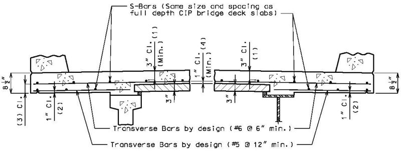
|
| (1) Guidance for minimum concrete cover for top bars is 3 inches and shall meet EPG 751.5.10 Reinforcing Steel Detailing. This cover is required for #6 top bars used in tandem. An exception is made for larger bars, e.g. #8 longitudinal bars where cover will need to be reduced to 2 3/4 inches. (2) See EPG 751.5.10 Reinforcing Steel Detailing. |
751.10.1.8 Epoxy Coated Reinforcement
For epoxy coated reinforcement requirements, see EPG 751.5.9.2.2 Epoxy Coated Reinforcement Requirements.
751.10.1.9 Standard Parabolic Crown
Use parabolic rounding for all bridges at the crown of the roadway except for the bridges with superelevated slabs. The profile grade will be at the intersection of the two cross-slopes if it is located at the crown of the roadway.
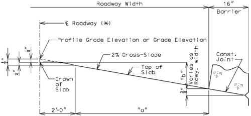
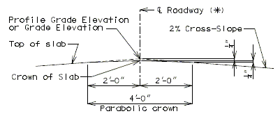
751.10.1.10 Slab Offsets for Curved Bridges
The plans for horizontally curved bridges shall contain the slab offset detail shown in the figure, below.
Slab offsets from chords, between the centerline of bents, shall be detailed at every 5 feet along the chord. On circular curves, these offsets shall be spaced from the center of the chord to ensure that the largest offset is recorded.
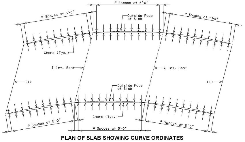
- (1) “End of Slab” when at an end bent with no expansion joint system (including sliding slabs). When there is an expansion joint system at an end bent or intermediate bent, identify the exposed face of the joint system (i.e., “Exposed Face of Armor” for strip seal, “Exposed Face of Angle” for compression seal, “Exposed Face of W14x43 Web” for finger plate, etc.).
751.10.1.11 Slab Elevations
Slab elevations are used to determine haunching at the tenth points of steel and prestressed girder or beam spans seventy-five feet in length or longer. Spans shorter than 75 feet long use quarter points.
Theoretical Bottom of Slab Elevations at Centerline of Girder (Prior to Forming for Slab)
Elevations and details for theoretical bottom of slab elevations at centerline of girder (prior to forming for slab) shall be provided on all beam or girder type structures and all spread beam type structures.
Steel Girders
Elevations are determined by adding DL1 and DL2 deflections to finished bottom of slab elevations. DL1 deflections are reduced by the percent of dead load deflection due to the weight of structural steel. DL2 deflections are reduced by the percent of dead load deflection due to future wearing surface.
P/S I-Girders
Theoretical camber of girder after erection (estimated at 90 days) minus theoretical final camber after slab is poured (estimated at 90 days) is used to determine DL1 deflection.
Typical Details and Example Elevation Calculation
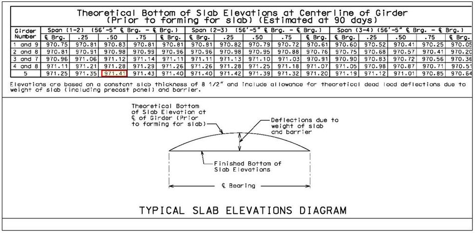
| Example: | |
|---|---|
| 972.0715 | Finished top of Slab Elevation at centerline of girder |
| - 0.7083 | Slab Thickness |
| 971.3632 | Finished Bottom of Slab Elevation at centerline of girder |
| + 0.0478 | Theoretical Dead Load Deflection due to weight of slab and barrier or railing. |
| 971.4110 | Theoretical Bottom of Slab Elevation at centerline Girder (Prior to Forming for Slab) |
| 971.41 | (USE) Theoretical Bottom of Slab Elevation at centerline Girder (Prior to Forming for Slab) |
The diagram detail and blank quarter point and tenth point elevations tables are available in MicroStation under Tasks: Slab Sheet Details. The available elevations tables were created for prestressed and simple steel spans but may be used for continuous steel spans by duplicating the elevations at the bearings of intermediate bents in each of the centerline bearing columns of adjoining spans.
751.10.1.12 Slab Pouring Sequences and Construction Joints
Concrete pouring and finishing with/without rates are based on the following:
One pouring sequence must be provided that will permit a minimum pouring rate of 25 cubic yards per hour without retarder for steel structures and with retarder for prestressed structures. A minimum finishing rate of 20 linear feet per hour is also required. If these two requirements conflict, see the Structural Project Manager.
Continuous steel structures will normally require a Case I pouring sequence with the basic sequence being a skip pour arrangement. Minimum yardage for the basic sequence shall not be less than 25 cubic yards per hour. Computation of minimum yardage for alternate pours is outlined below. If the rate for the alternate pours should be 25 yards or less, the skip pour basic sequence may be eliminated with the first alternate pour becoming the basic sequence.
Use of retarder is required for prestressed structures and a Case II sequence * is normally required. The minimum rate of pour will be determined by the 20 feet per hour minimum finishing rate but shall not be less than 25 cubic yards per hour. For span lengths over 80 feet or special structures (segmental, etc.), see Structural Project Manager.
- = Slab width (out to out of barriers, or width being poured)(feet)
- = Slab thickness (feet)
- = Volume of concrete (cubic yards/hour)
- (two span) = Length of longest alternate "A" pour (feet)
- (more than two span) = Length of longest span (feet)
(*) Case II sequence is used for all prestressed structures, except if slab area of one span is greater than 3,000 square feet, use Case I.
Minimum rate of pour per hour for alternate pours (reduce V by 25% for precast prestressed panels).
| Without Retarder: | |
|---|---|
| Not less than | |
| With Retarder: | |
| Not less than | |
| Simple Span: | |
| Not less than | |
Extra long spans or extra wide bridges that indicate a basic rate greater than 25 cubic yards per hour are to be checked with the Structural Project Manager.
The minimum rate of pour for solid slab or voided slabs is 20 linear feet of bridge per hour and not less than 25 cubic yards per hour. Check pouring rates with Structural Project Manager if it is indicated necessary to exceed the basic minimum rate of 25 cubic yards per hour.
The largest minimum rate of pour for alternate pours is 50 cubic yards per hour in rural areas or 65 cubic yards per hour in urban areas.
Slab Pouring Sequence Transverse Construction Joints
Slab Pouring Sequence - Bridges on Grade
All bridges on straight grades shall be poured up grade.
All bridges on vertical curves with both negative and positive grades may be poured either up or down grade.
Transverse Construction Joint
On occasion, it will be necessary to off-set the transverse construction joint. For example, on bridges with large skews, wide roadways or short spans, the transverse construction joint could extend across the intermediate bent. Should this occur, the off-set or sawtooth construction joint shall be used.
It is desirable to relocate construction joint within reason (6 inches±) should it cross additional negative slab reinforcement. However, this shall not be considered critical.
Since the off-set construction joint creates construction problems, the designer shall avoid its use, if possible. Consult the Structural Project Manager for possible variations. See illustrations below for clarification.
Longitudinal Construction Joints
Wide Flange Beam, Plate Girder and Prestressed Girder
Normally, the maximum finishing width is 54 feet. Larger widths require longitudinal construction joints. Normally, the widest section of slab shall be poured first. During construction, the engineer may opt to eliminate this construction joint. Include note (H6.18) on roadways with longitudinal construction joints to address this option.
The finishing width shall be adjusted to finish the surface approximately parallel to the skew (i.e., skewed transverse construction joints) if the angle of skew exceeds 45° or if the angle of skew exceeds 30° and the ratio of placement width divided by span lengths equals or exceeds 0.8.

|
| Wide Flange Beam or Plate Girder |
|---|

|
| Prestressed Girder |

|
| Voided Slab |
| (*) See Lap Splices of Tension Reinforcement - EPG 751.5 Standard Details |
Construction Joint Details for Full Depth CIP Bridge Deck Slabs Using Conventional or SIP Corrugated Steel Forms
The following transverse joint details shall be shown on the plans, preferably near the slab pouring sequence details.
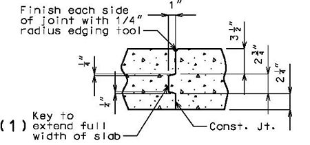
|
| Slab Construction Joint Details |
|---|
| (1) Use “Key to extend full width and length of deck” when a longitudinal joint is also required (primarily with stage construction or wide bridges). |
Construction Joint Details for Partial Depth Precast Prestressed Panel Bridge Deck Slabs
The following transverse joint details shall be shown on the plans, preferably near the slab pouring sequence details.

|
| Slab Construction Joint Details |
|---|
| (1) Use “Key to extend full width and length of full depth slab” when a longitudinal joint is also required in a girder bay without precast prestressed panels (primarily with stage construction). (2) Use “Const. joint to extend full width and length of slab” when a longitudinal joint is also required in a girder bay with precast prestressed panels (primarily with wide bridges). |
Pouring and Finishing Concrete Bridge Deck Slabs
| Span Ratio n | |||||||||||||
|---|---|---|---|---|---|---|---|---|---|---|---|---|---|
| Spans | Coef. | 1.0 | 1.1 | 1.2 | 1.25 | 1.3 | 1.4 | 1.5 | 1.6 | 1.7 | 1.8 | 1.9 | 2.0 |
| 2 | a | .4 | -- | -- | -- | -- | -- | -- | -- | -- | -- | -- | -- |
| 3 | a | .4 | .35 | .30 | .28 | .25 | .22 | .20 | .19 | .18 | .17 | .16 | .15 |
| 3 | b | .15 | .18 | .21 | .25 | .30 | .33 | .35 | .36 | .37 | .38 | .39 | .40 |
| 4 & 5 | a | .4 | .35 | .30 | .28 | .25 | .22 | .20 | .19 | .18 | .17 | .16 | .15 |
| 4 & 5 | b | .15 | .18 | .21 | .25 | .30 | .33 | .35 | .36 | .37 | .38 | .39 | .40 |
| 4 & 5 | c | .15 | .18 | .21 | .25 | .30 | .33 | .35 | .36 | .37 | .38 | .39 | .40 |
Use adjacent spans for ratio n.
Span lengths to be used are center to center of bearing.
Modify the dimensions produced by the coefficients on wide roadways and large skews if they produce construction joints that are within 6 inches of the additional negative slab reinforcement.
Dimensions, except for terminal lengths of end spans, shall be to the nearest foot.
For 6 & 7 spans, use same coefficients for a, b, & c as for 4 and 5 spans.
SLAB POURING SEQUENCE
The pouring sequences given in the tables below may not be applicable for bridges with multiple units (i.e, bridges with intermediate expansion joints) - see Structural Project Manager or Liaison.
Slab pours shown are to be reversed for bridges on a minus grade.
For prestressed structures, "aL" and "bnL" may be made shorter than that indicated by the coefficients to balance pours.
PLATE GIRDER AND PRESTRESSED CONCRETE: (2-SPAN)
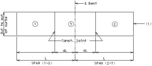
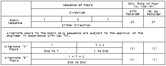
PLATE GIRDER AND PRESTRESSED CONCRETE: (3-SPAN)
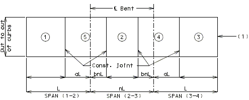
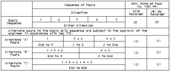
I-BEAM, PLATE GIRDER AND PRESTRESSED CONCRETE: (4-SPAN)
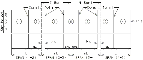
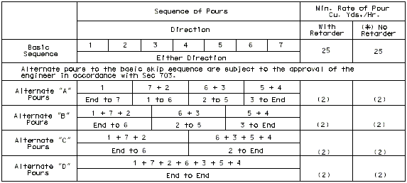
I-BEAM, PLATE GIRDER AND PRESTRESSED CONCRETE: (5-SPAN)
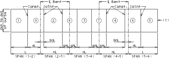
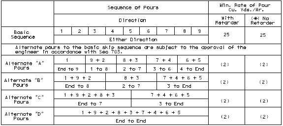
PRESTRESSED CONCRETE: (2-SPAN)
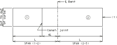

PRESTRESSED CONCRETE: (3-SPAN)
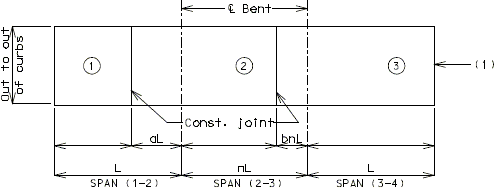
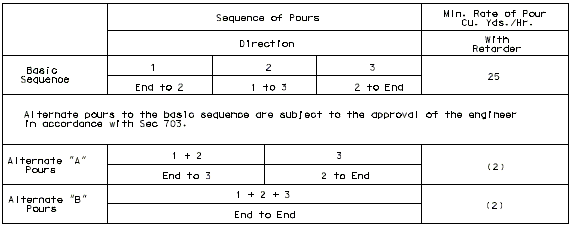
PRESTRESSED CONCRETE: (4-SPAN)
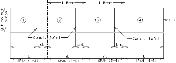
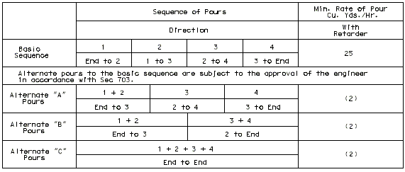
PRESTRESSED CONCRETE: (5-SPAN)
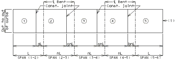
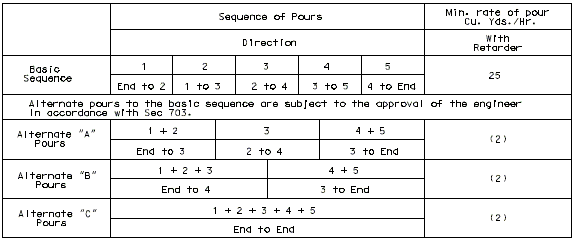
| (1) | “End of Slab” when at an end bent with no expansion joint system (including sliding slabs). When there is an expansion joint system at an end bent or intermediate bent, identify the exposed face of the joint system (i.e., “Exposed Face of Armor” for strip seal, “Exposed Face of Angle” for compression seal, “Exposed Face of W14x43 Web” for finger plate, etc.). |
| (2) | Minimum pour rates. |
751.10.1.13 Drip Groove
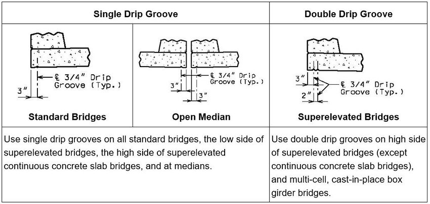
751.10.1.14 Girder and Beam Haunch Reinforcement
General
- Steel Beams and Girders
- Haunch reinforcement consisting of #4 hairpin bars shall be provided where the embedment of existing studs into a new slab is less than 2 inches or for an excessive haunch where at centerline of beam or girder exceeds 3 inches.
- Prestressed Beams or Girders with Full Depth CIP Decks (Conventional or SIP forms)
- Haunch reinforcement consisting of #4 hairpin bars shall be provided when haunch at centerline of beam or girder exceeds:
- 3 inches for Type 2, 3, 4 girders
- 4 inches for Type 6, 7 and 8 girders (bulb-tee), NU girders and spread beams
- Prestressed Beams or Girders and Partial Depth CIP Decks (Prestressed Panels)
- Haunch reinforcement should not be required with precast prestressed panel decks due to joint filler limits.
Details
When possible, hairpin bars and tie bars shall be clearly shown on the section thru slab; otherwise, a part section showing hairpins shall be provided. Include these bars in the slab reinforcing steel quantities.
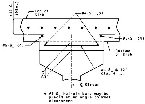
- (1) Top of slab to bottom of longitudinal bars.
- (2) Haunch limit specified above.
- (3) Use tie bars at the discretion of the Structural Project Manager or the Structural Liaison Engineer.
- (4) The bottom longitudinal bars should be shown to be used as tie bars or add a note allowing adjustment.
- (5) Add asterisked note when there is insufficient clearance or hairpins with varying vertical heights may be used.
Hairpin bars and tie bars shall be shown on the plan of slab. Splice lengths of the tie bars shall also be specified if required. For deck replacements without a plan of slab the hairpin bars and tie bars shall be shown either on a part plan detail or in a table. Include these bars in the slab reinforcing steel quantities.

Hairpin bars and tie bars shall be included in the bill of reinforcing. Include these bars in the slab reinforcing steel quantities.
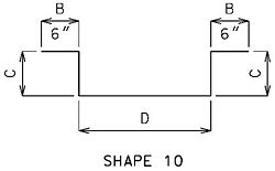 |
“C” is based on the top horizontal legs located above the longitudinal bars of the bottom mat at the location of the maximum haunch. |
751.10.1.15 Deck Concrete Finishing
Bridge decks are normally finished with an approved mechanical finishing machine per Sec 703.3.5. The use of a vibratory screed in place of a finishing machine is allowed if the guidance below is satisfied or with approval of the SPM, SLE or owner’s representative for a particular bridge. Although vibratory screeds may contribute to an overworked concrete surface where durability of the deck may be reduced, there are applications where the weight and bulk of the finishing machine may not be practical. For instance, most re-decks consist of steel wide flange beams where the contractor may have to heavily brace the exterior beams for the finishing machine. Using a vibratory screed may allow the contractor to use less bracing and finish with much lighter equipment. In addition, a vibratory screed is useful when the finishing machine framework is too wide and would interfere with traffic or adjacent physical obstacles. If a vibratory screed is allowed for deck finishing, add note B3.25 (A2.14 for box culverts) on the bridge plans.
Guidance for allowing a vibratory screed:
- (1) Bridges with exterior steel beams with the web depth 30 inches or less and all of the following are met:
- Bridge is located on a minor road.
- Bridge width not greater than 32 feet.
- (2) Re-decks on thru trusses with roadway width less than 26 feet and limited horizontal clearance between truss members and edge of deck.
- (3) Bridges with staged pours less than 12 feet and limited available horizontal clearance. Modify note B3.25 to indicate applicable stage(s).
- (4) New box culverts with top slab used as the riding surface.
- (5) Widenings less than 12 feet wide or with limited available horizontal clearance.
751.10.1.16 Plan of Slab Details
Details of plan of slab and part plan of slab (showing top and bottom slab reinforcing, slab pouring sequence, slab drains, etc.) shall include:
- When there is no expansion joint system at the end bent (including sliding slabs), the end of slab shall be identified.
- When there is an expansion joint system at the end bent, the concrete on top of the backwall shall not be shown on the plan of slab. Show end of slab in other details.
- When there is an expansion joint system at an end bent or intermediate bent, identify the exposed face of the joint system (i.e., “Exposed Face of Armor” for strip seal, “Exposed Face of Angle” for compression seal, “Exposed Face of W14x43 Web” for finger plate, etc.).
The calculation of quantities for bridge slabs shall be in accordance with EPG 751.6.2.10 Bridge Slabs.
751.10.2 Stay-in-Place Bridge Deck Forms
751.10.2.1 Precast Prestressed (P/C P/S) Concrete Panel Forms - Design
General Guidelines
Use of precast prestressed panel forms shall be based on the approval of the Structural Project Manager, Structural Liaison Engineer or owner’s representative. A partial depth cast-in-place deck shall consist of three-inch precast prestressed panel forms with a 5 1/2-inch minimum cast-in-place concrete topping.
Precast prestressed panels may be used on horizontally curved steel and concrete structures based upon the approval of the Structural Project Manager or Structural Liaison Engineer. Consideration shall be given to the superelevation magnitude and its effects related to joint filler thickness and width requirements, top flange width requirements for setting panels, increased slab dead load, and any curvature effects on the design and details of the panels related to stability of the panels during a slab pour ensuring that sliding or shifting of the panels isn’t possible and related to cutting of the panels on skew. (Fabricating “wedge” shaped panel is dependent upon end strand cover and strand spacing requirements and therefore limited.)
- For MoDOT Standard Girders Type 2, 3 and 4, and Steel Girders: Panels shall be set on joint filler using optionally (by contractor) either preformed fiber joint material in accordance with Sec 1057 of Missouri Standard Specifications or polystyrene bedding material in accordance with Sec 1073 of Missouri Standard Specifications. Joint filler thickness shall be a minimum of 1 in. and a maximum of 2 inches. Joint filler width shall be 1 1/2 in. except at splice plates where 3/4 in. shall be used to clear splice bolts. Joint filler thickness may be reduced to a minimum of 1/4 in. over splice plates on steel structures, however, the width of joint filler shall match the width of the panel on the splice plate when the joint thickness is less than 1/2 inch. For concrete structures the joint filler thickness may be varied within these limits to offset girder camber and account for deck cross-slope or at the contractor’s option a uniform 1 in. thickness may be used throughout. For steel structures the joint filler thickness shall be varied within these limits to account for deck cross-slope and varying top flange thicknesses.
- For MoDOT Standard Girders Type 6, 7 and 8, and NU Standard Girders, and Spread Voided Slab and Box Beams: Exceptions are made for these larger girders, where it is allowed to use up to a maximum joint filler thickness of 4 inches in order to reduce the likelihood of adding steps on long span girders because of camber and to meet minimum haunch and deck cross-slope criteria. Joint filler width shall be 3 inches. Setting the width of the joint filler to 3 inches allows for an increased bearing area on the thin flange tips in the case of NU and Bulb-Tee girders, simplifies manufacturing by eliminating the need to produce panels of multiple widths, eliminates joint filler width variability based on joint filler height, and provides a means for addressing girder sweep on long spans.
For both concrete and steel structures the same joint filler thickness shall be used under any one edge of any panel. The maximum change in thickness between adjacent panels shall be 1/4 inch for steel spans and 1/2 inch for concrete spans.
As per the above criteria, the following shall control the panel width, measured parallel to the prestressing strands:
- Maximum Panel Width = 9’-6”
- Minimum Panel Width = 4’-0”
Precast prestressed panels shall be used in at least two adjacent bays for each stage of construction. Panels are not designed for simple span (single bay) composite live loading.
When a barrier (railing or median) is permanently required on the structure other than at the edge of the deck or where panels are not used for other reasons, panels shall not be used in the bay underneath the barrier.
Design Stresses
Concrete for precast prestressed panels shall be Class A-1 with = 6.0 ksi and = 4.0 ksi. Concrete for the cast-in-place portion of the deck shall be Class B-2 with = 4.0 ksi. The panels are considered as beams for analysis and design.
Prestressing steel shall be AASHTO M 203 (ASTM A 416) – Uncoated Seven-Wire, Low-Relaxation Strands. The strands will be Grade 270, have a nominal diameter of 3/8 in., area of 0.085 square inches, and be spaced at 4 1/2 inches in the panels.
= ultimate strength of strands = 270 ksi = yield strength of strands = 0.9 = 243 ksi = modulus of elasticity of strands = 28,500 ksi Area of Strand = Astra = 0.085 sq. in./strand Initial prestressing stress = fsi = (0.75)(270 ksi) = 202.5 ksi Initial prestressing force = Astra x fsi = (0.085 sq. in./strand)(202.5 ksi) = 17.2 kips/strand
Load Definitions
Non-Composite Loading – This is the loading that occurs before the cast-in-place concrete slab hardens and acts compositely with the precast prestressed panels. The contributions to the Non-Composite Loading are as follows:
- Precast Prestressed Panel, DC
- Cast-In-Place Slab, DC
- Additional Slab Weight due to excess haunch, DC
- Construction Load of 50 lb/ft2
Composite Loading – This is the loading that occurs after the cast-in-place concrete slab hardens and acts compositely with the precast prestressed panels. The contributions to Composite Loading are as follows:
- Future Wearing Surface, DW
- Barrier, DC
- Design Live Load, LL
Prestress Losses
Refined estimates of time-dependent losses are used, based on LRFD 5.9.5.4, as opposed to approximate lump sum estimate of losses in LRFD 5.9.5.3.
The prestress losses shall be calculated to investigate concrete stresses at two different stages.
- Temporary stresses immediately after transfer:
- Final stresses
Load Combinations for Stress Checks
Note: Units of stress are in ksi.
Construction Loading = DC + 0.050 ksf with Effective Prestressing Force
- Allowable Concrete Tensile Stress =
- Allowable Concrete Compressive Stress =
Service I = Permanent Loads with Effective Prestressing Force
- Allowable Concrete Compressive Stress =
Service I = Live Load + Half the Sum of Permanent Loads and Effective Prestressing Force
- Allowable Concrete Compressive Stress =
Service I = 1.0DC + 1.0DW + 1.0LL with Effective Prestressing Force
- Allowable Concrete Compressive Stress =
Service III = 1.0DC + 1.0DW + 0.8LL with Effective Prestressing Force
- Allowable Concrete Tensile Stress =
Strength I = 1.25*DC + 1.5*DW + 1.75LL with Effective Prestressing Force
- Factored Moment Resistance =
- Where:
- = as calculated in LRFD 5.5.4.2.1
Reinforcement Check
- Minimum Requirement =
751.10.2.2 Precast Prestressed (P/C P/S) Concrete Panel Forms - Details
| Bridge Standard Drawings |
| Prestressed Panels |
751.10.2.3 Corrugated Steel Forms
General Guidelines
Corrugated steel forms may be used on horizontally curved steel structures and prestressed girder, voided slab, and box girder beam structures.
Use of corrugated steel forms shall be based on the approval of the Structural Project Manager, Structural Liaison Engineer or owner's representative.
Use of corrugated steel forms should be based on the final expected conditions of operation and expected in-service performance which should include reviewing the type of crossing, AADT under, salt spray under, surrounding bridge structure conditions, staged construction, etc.
Use of corrugated steel forms should be considered as an alternate method of slab forming where use of precast prestressed concrete panel forms is not practical or not allowed.
Design loading for bridge design shall include an allowance for the dead weight of the steel forms. Use 4 psf dead loading for form spans up to 10 feet beyond which either sagging of the form spans and the additional dead weight of the concrete may need to be considered in accordance with LRFD 9.7.4 or a greater dead loading for form spans may need to be considered.
Design of corrugated steel forms is the responsibility of the contractor in accordance with Sec 703.
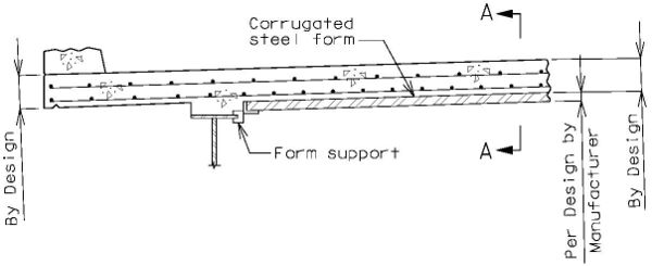
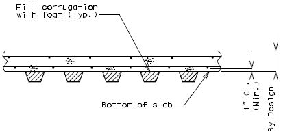
751.10.2.4 Transparent Forms
General Guidelines
Transparent forms may be used on steel and prestressed girder, voided slab, and box girder beam structures.
Transparent forms are preferred to corrugated steel forms for bridges that carry a minimum of 10,000 AADT. Transparent forms should also be considered for bridges spanning railroads, rivers, or roadways with traffic volumes greater than 10,000 AADT.
Use of transparent forms shall be based on the approval of the Structural Project Manager, Structural Liaison Engineer or owner’s representative.
Use of transparent forms should be based on the final expected conditions of operation and expected in-service performance which should include reviewing the type of crossing, AADT under, salt spray under, surrounding bridge structure conditions, staged construction, etc.
When a barrier is permanently required over a girder bay, Stay-in-place transparent forms are preferred in the bay underneath the barrier to allow for inspection of the bottom of deck after barrier collisions.
Design loading for bridge design shall include an allowance for the dead weight of the transparent forms. Use 5 psf dead loading for form spans up to 8 feet. The maximum form span for transparent forms is 8 feet.
Design of transparent forms is the responsibility of the contractor in accordance with Sec 703.
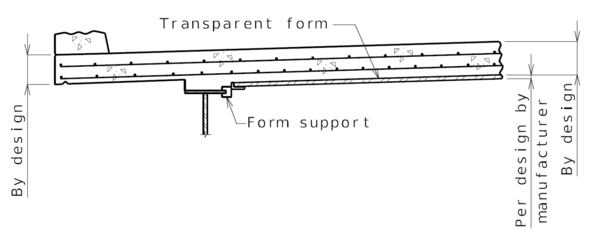
751.10.3 Bridge Deck Drainage - Slab Drains
751.10.3.1 Type, Alignment and Spacing
Type
Steel Slab Drains:
- 8" x 4" x 1/4" steel tubing.
- Standard steel slab drain made optional with standard polymer slab drain.
- Galvanized (shall not be color coated)
- No restrictions on use where slab drains are allowed.
Fiberglass Reinforced Polymer (FRP) Slab Drains:
- 8" x 4" x 1/4" (Nominal O.D.)
- Standard polymer slab drain made optional with standard steel drain.
- Restricted use could include stream crossings with moderate to heavy debris flow. Consult Structural Project Manager or Structural Liaison Engineer.
- Restricted use for new or existing bridges with wearing surfaces and rehabilitation, surfacing and widening jobs involving slab drain work and are subject to approval by Structural Project Manager or Structural Liaison Engineer.
- The standard color shall be Gray (Federal Standard #26373). Optional colors which are the same colors allowed for steel superstructures include Brown (Federal Standard #30045), Black (Federal Standard #17038), Dark Blue (Federal Standard #25052) and Bright Blue (Federal Standard #25095). Consult with FRP drain manufacturer/supplier to verify optional color availability and cost.
Alignment
All standard crown roadways shall have the 8" x 4" steel tubing or 8” x 4” FRP placed with the 8" side perpendicular to the barrier whenever possible.
All super-elevated roadways shall have the 8" x 4" steel tubing or 8” x 4” FRP placed with the 8" side parallel to the barrier.
Slab Drain Spacing
Slab drain spacing shall be designed according to the 1986 FHWA report FHWA/RD-87/014 "Bridge Deck Drainage Guidelines" along with information acquired from the 1995 University of Missouri Rolla report "Scupper Interception Efficiency." The following general guidelines may be refined if justified by appropriate calculations by other methods of design such as the procedure for Flat Bridges in FHWA “HEC 21, Design of Bridge Deck Drainage”. The variations to the design and general requirements listed below should be discussed with the appropriate Liaison or Project Manager on a project by project basis before being incorporated into the final design.
General Requirements for Location and Spacing of Slab Drains
1. Drains shall be spaced no closer than 8 ft. center to center.
2. Drains shall be omitted on high side of super-elevation bridges.
3. Drains shall not be located over unprotected fill. If drains are needed, fill should be protected with use of rock blanket with Permanent Erosion Control Geotextile, or concrete slope protection. (See General Requirement #9a for bridge abutments with MSE walls.)
4. Drains shall be omitted in areas where water can fall on the roadway or shoulder on all grade separations.
5. Drains shall be omitted on railroad overpasses when water will fall on or drain on to railroad right of way.
6. For Bridges with slopes less than 0.5%, space drains at about 10 ft. centers where possible.
7. Use consistent spacing for drains when possible.
8. Drains shall be placed at least 5 ft. from the face of substructure beam.
9a. Drains shall be placed at least 10 ft. from front of MSE wall and should be discharge on stone riprap or rock blanket. Deck drainage shall not be allowed to be discharged near MSE wall toe or over MSE wall backfill area in order to prevent external soil erosion and front face wall staining (FHWA NHI-10-024). In special cases, where deck drainage is required within 10 ft. from MSE wall in order to meet the required number of drains, vertical drains deflected away from wall face, geotextile lined riprap stone or other means should be used to prevent external soil erosion. Free falling water exceeding 25 ft. will sufficiently disperse water. Riprap or splash blocks could be considered for lesser heights (FHWA-SA-92-010).
9b. Drains shall not be placed directly over MSE wall backfill area. See EPG 751.24.2.1 Design.
10. Drains shall be dimensioned along centerline of exterior girder to facilitate placement of coil inserts or holes in girders.
11. For all sag vertical curves, locate the points at which the slope is 0.5% on either side of the low point, and space drains on 10 ft. centers between them where possible. Use equations in this section for spacing drains for the remainder of the curve.
12. If location restrictions apply, the same number of drains as calculated by equations in this section shall be placed on the bridge when possible. The designer is responsible for relocating drains. Additional drains may be added to meet design spread requirements.
13. The length of the approach slab shall be included in the length of the bridge for spacing or design spread computations. Do not place slab drains on the approach slab.
14. All gutter flow should be intercepted above transition points and expansion devices.
15. For all crest vertical curves, where the slope is less than 0.5%, consideration should be given to spacing drains at 10 ft. centers for long flattened curves, small shoulders, high speed, high AADT, or superelevation with approval of the Structural Project Manager or Structural Liaison Engineer.
16. For round drains, location of drains shall follow same requirements as for rectangular drains. Spacing shall be determined using the same method except as modified by adjusting the number of round drains in order to achieve a total cross sectional area of round drains approximately equal to that of rectangular drains. (Use 8” dimension parallel to barrier.)
Calculation of spacing to first slab drain
The first slab drain either side from the high point of the bridge shall be calculated according the following equation. If the value of L1 is greater than the bridge length, slab drains are not required.
- = Distance from high point to first slab drain (ft.)
- = Cross slope of slab (ft./ft.)
- = Longitudinal slope of bridge (ft./ft.). For vertical curve bridges, "S" is the longitudinal slope at the location of the drain being analyzed. A linear approximation can be used to simplify the calculations.
- = Design spread (ft.). The spread is the width of gutter flow. The criteria in the following table shall be used to determine the design spread.
| Roadway Classification | Design Speed | Maximum Spread |
|---|---|---|
| Interstate | All | Up to the shoulder width, with a 10’ max. |
| Major | ≥ 45 mph | Up to the shoulder width, with a 10’ max. |
| < 45 mph | Shoulder + 3 ft. (10’ max.) | |
| Minor | All | Shoulder + 3 ft. (10’ max.) |
- = Ratio of impervious to pervious drain area. On a bridge deck, most rainfall runs off, except at the beginning of a storm when rain wets the bridge deck and fills small depression areas. Design of slab drain spacing assumes the bridge deck is wetted, therefore a "" value of 1.0 is recommended.
- = Manning's coefficient of friction. For typical pavements, "" equal to 0.016 is used.
- = Design rainfall intensity (in./hr.). The "Rational Method" as outlined in "Hydraulic Engineering Circular-12, (HEC-12)" with a 10 year frequency for a 10 minute time period shall be used to calculate the design rainfall. For bridges with sag curves or with wide deck drainage areas where the design speed is > 45 mph. (i.e., multi-lane super-elevated deck) 10 year frequency for a 5 minute time period may be used to calculate the design rainfall. Missouri's intensity varies across the state for these frequency and time period combinations. Therefore an "" value of 6.50 in./hr. is recommended to determine slab drain spacing in most cases. An "" value of 9.00 in./hr. is recommended for bridges with sag curves or with wide deck drainage areas where the design speed is > 45 mph.
- For details regarding roadway design frequency only, see EPG 640.1.2.1 Design Frequency.
- = Width of deck drainage area (ft.). For crowned roadways use distance from top of crown to barrier face and for super-elevated bridges use distance from face of barrier to face of barrier.
Calculation of Additional Slab Drain Spacing
Once the first slab drain has been located, slab drain efficiency "Es" is required to determine the location of additional slab drains. Given the efficiency of the slab drain, the amount of flow intercepted by the first slab drain (q)i is determined by (q)i =Es(QT)i where (QT) is the flow at which the gutter is filled to the design spread (T) at slab drain #1 and is determined by the equation:
- (cu. ft./second)
Interception flow decreases the flow in the gutter by q (intercepted). This flow must be replaced before another slab drain is required. Flow in the gutter at the second slab drain is given by the equation:
- (cu. ft./second)
Another slab drain is located when runoff minus intercepted flow equals flow in the gutter filled to the design spread at length where is the total length of bridge to .
For tangent sections the additional theoretical slab drain spacing are constant. For vertical curve sections the theoretical slab drain spacing are variable and require the designer to repeat the process till the end of the bridge. Theoretical spacing should be revised to consider ease of spacing.
Calculation of Slab Drain Interception Efficiency
Slab drain interception efficiency is that fraction of gutter flow removed by the slab drain. FHWA's report called "Bridge Deck Drainage Guidelines" gives an approximation for for small grates and low gutter velocities, which is a fraction of triangular gutter flow passing over a slab drain located next to the barrier.
- = width of slab drain normal to the flow (ft).
- = Design spread.
In UMR's report "Scupper Interception Efficiency" emperical data is used to determine a more precise efficiency coefficient. They state that the slab drain efficiency can be closely approximated by the equation , where is a percent (%) and must be divided by 100 for use in the flow equations.
- = Longitudinal slope of bridge at slab drain location.
- and = Emperical coefficients dependent on the bridge cross-slope. The following tables can be used to determine and .
The UMR method shall be used whenever possible because of its ability to account for increased velocities with increased slopes in its efficiency coefficient. When the design spread "" is other than 6 feet, the FHWA method must be used.
| 8-Inch Dimension Perpendicular to Barrier | 8-Inch Dimension Parallel to Barrier | |||||
|---|---|---|---|---|---|---|
| Cross-Slope | a | b | Cross-Slope | a | b | |
| 0.010 | 14.580 | -0.180 | 0.010 | 9.170 | -0.230 | |
| 0.016 | 6.670 | -0.340 | 0.016 | 7.060 | -0.280 | |
| 0.020 | 3.550 | -0.450 | 0.020 | 5.620 | -0.320 | |
| 0.030 | 2.080 | -0.500 | 0.030 | 4.670 | -0.320 | |
| 0.040 | 2.080 | -0.440 | 0.040 | 3.060 | -0.370 | |
| 0.050 | 3.680 | -0.280 | 0.050 | 3.660 | -0.300 | |
| 0.060 | 5.510 | -0.140 | 0.060 | 4.560 | -0.210 | |
| 0.070 | 4.550 | -0.160 | 0.070 | 5.500 | -0.130 | |
| 0.080 | 5.420 | -0.110 | 0.080 | 5.420 | -0.110 | |
751.10.3.2 Details
751.10.3.2.1 New Structure Without Wearing Surface Slab Drains - Details
| Bridge Standard Drawings |
| Slab Drains |
| Prestressed Member Type | Dimension A | Dimension B | Standard Drawing |
|---|---|---|---|
| Type 2, 3 & 4 I-Girders | 2’-9½“ | 2’-5½“ | S_DRA05 |
| Type 6 I-Girder | 3’-3” | 2’-11” | S_DRA05 |
| Type 7 & 8 Bulb-Tees | 4’-0” | 3’-8” | S_DRA01 |
| NU Girders | 4’-3⅛” | 3’-11⅛“ | S_DRA06 |
| Box Beams | 4’-3” | 3’-11” | S_DRA08 |
| Prestressed Member Type | Dimension C | Dimension D | Standard Drawing |
|---|---|---|---|
| Type 2, 3 & 4 I-Girders | 2’-3⅞“ | 22⅛“ | N/A |
| Type 6 I-Girder | 2’-9⅜” | 2’-3⅝” | N/A |
| Type 7 & 8 Bulb-Tees | 3’-6⅜” | 3’0⅝” | S_DRA02 |
| NU Girders | 3’-9½” | 3’-3¾“ | S_DRA07 |
| Box Beams | 3’-9⅜” | 3’-3⅝” | S_DRA09 |
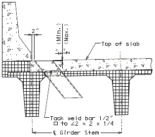
|
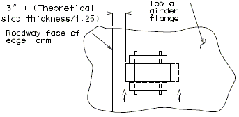
|
| Part Section of Slab at Drain | Part Plan of Drain Blockout |
|---|---|
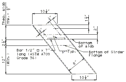
|
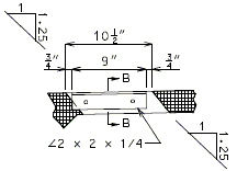
|
| Part Section A-A | |

| |
| Elevation of Drain | Section B-B |

| |
| Plan of Drain | |
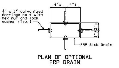 |
751.10.3.2.2 Structure with Wearing Surface Slab Drains – Details
See EPG 751.40.5.1 Structure with Wearing Surface Slab Drains - Details. The details shown in this article are sufficient for new structures with a wearing surface.
751.10.3.3 General Requirements for Location of Slab Drains

- Notes:
- * Slab drains spaced in accordance with above figures.
- Notes:
For Drainage Guidance, see EPG 751.24.2.1 Design.

- Notes:
- * Slab drains spaced in accordance with above figures
- ** For closed expansion joint, collect water at end and discharge to drainage system using conduit.
- For open expansion joint, provide drain trough with positive slope; collect water at lower end and discharge into drainage system using conduit.
- Notes:
For Drainage Guidance, see EPG 751.24.2.1 Design.
751.10.4 Conduit Systems
General
Conduit systems shall be provided on structures when specified on the Design Layout.
All conduits shall be rigid, nonmetallic, Schedule 40, heavy wall polyvinyl chloride (PVC) and in accordance with Sec 1060.
All conduit fittings for PVC conduits shall be in accordance with Sec 1060.
All conduit clamps, if required, shall be commercially available, nonmetallic conduit clamps and approved by the engineer.
Drainage shall be provided at low points or other critical locations of all conduits and all junction boxes in accordance with Sec 707. All conduits shall be sloped to drain where possible.
Junction boxes shall be NEMA 4 or NEMA 4X enclosures and in accordance with Sec 1062 except as shown on plans.
Deflection couplings at the end of the wings shall be required for probable thermal movements of the structure and ground movements.
Conduit Sizing and Placement Guidelines
Conduit sizes shall be determined realistically and practically by the core team based on the project need and shall be specified on the Design Layout.
Conduit should be placed internal to the structure encased in concrete unless the number of conduits required will not allow or there is no new concrete construction required and conduit must be placed external to the structure.
Single or multiple conduits may be used.
Minimum clearance to single or multiple conduits encased in concrete shall be 3 in., unless otherwise shown.
For single conduit placement, 3-inch round conduit is the maximum size preferred and shall be placed in the barrier.
- Single 4-inch round conduit may be used based on core team agreement that single 4-inch round conduit is absolutely required to meet the project need. Single 4-inch round conduit shall be placed in the barrier. (Practical difficulties in placing single 4-inch round conduit in the barrier could include sweeping from the outside face to the roadway face for junction box connections, increased interference with reinforcement, and less assurance for consolidated concrete under the conduit.)
- Single 2-inch round conduit may be placed in the slab when necessary, for example, when using barrier, either concrete or steel, that cannot accept conduit, or when surplus conduit must be run and placement in the barrier has been exhausted. Minimum clearance may be less than 3 inches.
For multiple conduit placement, three 2-inch round conduits, two 3-inch round conduits, or 2-inch plus 3-inch round conduit in combination may be used and shall be placed in the barrier.
- 4-inch round conduit shall not be combined with 2-inch round conduit or 3-inch round conduit where multiple conduits are to be placed in the barrier.
- Minimum clearance between conduits placed in the barrier shall be one inch.
- Placement method of multiple conduits shall be determined on a case-by-case basis. Other options include placing conduits on hangers or placing conduits in a deepened slab. Hangers and supports may be designed in accordance to a manufacturer’s specifications or they can be designed by a manufacturer for all external and internal loads. This depends on the number of conduits to be supported by hangers and the complexity of the design. Supporting connections like concrete anchors into the bridge must also be designed. Spacing of hangers may be made by the manufacturer and if necessary as shown on the plans. Resin anchors are not allowed for overhead installations. Special provisions may be required to instruct the contractor for this work.
All conduits shall be placed near the outside face of the barrier. For junction box placements at the roadway face of the barrier, conduit bends or sweeps shall be required for connecting the conduit to the junction boxes. Refer to Junction Boxes and Placement Guidelines.
Shift reinforcing steel in the field where necessary to clear all conduits and junction boxes.
For placement of single or multiple conduits in barrier other than as shown, sizing and placement shall similarly follow these guidelines. Review for applicability and special detailing.
Conduit placed external to the structure should be placed to the underside to avoid collecting dirt, debris and corroding moisture.
- May be attached to outside face of barrier if necessary.
- May be attached between girders.
- May be attached to underside of deck cantilevers but may not be attached near slab edge and not on slab bridge due to clearance issues.
- May not be attached to prestressed panels.
Expansion Fittings and Setting
Expansion fittings shall be required where expected bridge movements or conduit movements could cause distress in either conduits or structural supports of conduits.
Bridge movements of primary concern are thermal expansion and contraction, and live load deflections. Both types of movement can occur in structures with or without expansion devices and gaps. Thermal movements are typically predominant.
Conduit movements of primary concern are thermal expansion and contraction. Conduit placed internally to the structure, for example, is encased in concrete, and movement is considered restrained and coincident with the superstructure for which expansion fittings are required only where there is a gap in the concrete. Conduit placed externally to the structure is considered unrestrained for which expansion fittings shall be required.
For expansion fittings of conduit to be encased in concrete:
- Expansion fittings shall be specified on the bridge plans where conduit expansion and contraction will coincide with the expansion and contraction of the bridge superstructure, for example at expansion devices or gaps, i.e. open, closed or filled joints, including filled joints in the barrier where conduit is placed in the barrier.
- Estimated total expansion movement shall be specified on the bridge plans for each location where an expansion fitting is specified and based on the coefficient of thermal expansion for either a steel or concrete superstructure.
- Expansion fittings shall be designed to accommodate a movement of one and a half times the estimated total expansion movement at an open or closed joint, or 4 times the joint filler thickness rounded to the nearest half inch at a filled joint.
- Expansion fittings shall be placed and set in accordance with the manufacturer’s requirements and based on the air temperature at the time of setting given an estimated total expansion movement using a maximum temperature range of 150°F for steel or 120°F if concrete and a maximum temperature of 120°F for steel or 110°F for concrete.
For expansion fittings of conduit not to be encased in concrete:
- Conduit expansion and contraction should be allowed to occur independently of the bridge superstructure movement since the coefficient of thermal expansion for PVC conduit is three times greater than that for steel and concrete.
- The quantity and placement of additional expansion fittings shall be determined by the contractor and in accordance with the conduit manufacturer’s recommendations and specified on the bridge plans except:
- Expansion fittings shall be specified on the bridge plans at all superstructure open, closed or filled joints, and
- Expansion fittings shall be specified on the bridge plans for bridges without open or closed joints near where known conduit restraint will be imposed, for example, where conduits will be rigidly attached at bends or where conduit goes into the ground.
- Estimated total expansion movement shall be specified on the bridge plans for each location where an expansion fitting is specified and based on the thermal movement of PVC conduit for clamped, suspended or conduit otherwise externally supported to or from the superstructure using a coefficient of thermal expansion of 3.38 x 10⁻⁵ in./in./°F for PVC conduit.
- Expansion fittings shall be placed and set in accordance with the manufacturer’s requirements based on the air temperature at the time of setting given an estimated total conduit expansion movement using a maximum temperature range of 120°F and a maximum temperature of 110°F. For conduit exposed to direct sunlight, 30°F is added typically to the temperature range for design purposes only.
- Nonmetallic conduit clamps shall be specified to allow the conduit to move freely during expansion and contraction while properly securing it. Expansion fitting barrels should be clamped securely whereas conduit should be mounted loosely so that it can slide freely.
- Example 1 – Conduit encased in concrete. Plate Girder superstructure with expansion length of 300 ft.
- Δ (Steel) = (0.0000065)(150)(300)(12) = 3.51 in.
- Δ (Fitting) total = 1.5 x 3.51 = 5.27 in.
- Use 5 1/4 in. total expansion movement.
- Example 2 – Conduit encased in concrete. Expansion at 1/4 in. joint filler in barrier.
- Δ (Fitting) total = 4 x 0.25 = 1.0 in.
- Use 1 in. total expansion movement.
- Example 3 – Conduit not encased in concrete and not exposed to direct sunlight. Integral Abutment Bridge with expansion length of 150 ft.
- Δ (Conduit) = (0.0000338)(120)(150)(12) = 7.30 in.
- Δ (Fitting) total = 1.0 x 7.30 = 7.30 in.
- Use 7 1/2 in. total expansion movement for each expansion fitting placed at end of the bridge.
Deflection Coupling (Fitting) and Expansion Fitting:
- Deflection Coupling shall be specified on the bridge plans where conduit exits from the structure. Based on estimated total expansion movement of steel or concrete bridge structure determine how many Deflection Couplings are required. Deflection Coupling shall accommodate axial or parallel movement up to 3/4" and angular movement of up to 30° from normal position.
- When total movement is less than or equal to 1 1/2", provide deflection coupling without expansion fitting. When total movement is greater than 1 1/2", provide two deflection couplings or one deflection coupling and one expansion fitting.
- Example 1 - Conduit encased in concrete. Plate Girder superstructure with expansion length of 280 ft., and 150° temperature range.
- Δ (Steel) = (0.0000065)(150)(280)(12) = 3.28 in.
- Δ (Factored) total = 1.00 x 3.28 = 3.28 in.
- Δ (Fitting) movement for temp rise or fall = 3.28/2 = 1.64 in.
- Provide two deflection couplings or one deflection coupling and one expansion fitting.
- Example 2 - Conduit encased in concrete. Prestressed beam superstructure with expansion length of 173 feet, and 120° temperature range.
- Δ (Concrete)= (0.000006)(120)(173)(12) = 1.50 in.
- Δ (Factored) total = 1.00 x 1.50 = 1.50 in.
- Δ (Fitting) movement for temp rise or fall = 1.50/2 = 0.75 in.
- Provide one deflection coupling.
Junction Boxes and Placement
Size and location of junction boxes shall be specified on the bridge plans when a conduit system is required.
Maximum spacing between junction boxes shall be approximately 250 feet.
Junction boxes shall be required at each end of the bridge when conduit is required.
All junction boxes shall be placed in the wings at the outside face at each end of the bridge when spacing between the end bent junction boxes is less than 250 feet and district Traffic does not require an additional junction box on the bridge.
When spacing between the end bent junction boxes exceeds 250 feet, additional junction boxes shall be required and all junction boxes shall be placed in and at the roadway face of the barrier. (Junction box placement at the roadway face is preferred for easier accessibility for utility maintenance.)
Placement of junction boxes and covers complete-in-place shall be flush with the roadway face of the barrier. Junction boxes and covers may be recessed up to 1/4 inch.
Junction boxes should not be placed within 5 feet of an open, closed or filled joint in the barrier. Shift reinforcing steel in the field where necessary to clear all junction boxes.
Perimeter steel shall be required at all junction box placements at the roadway face of the barrier.
When 2-inch round conduit is placed in the slab, preferred placement of junction boxes shall be in the slab and in areas accessible from underneath the bridge.
| Junction Box Size Requirements | ||
|---|---|---|
| Junction Box Placement | Entering Conduit Size(s) | Junction Box Size1 |
| H x D x L2, inches | ||
| Concrete Barrier Type D Or Type H Or Abutment Wing |
Single 2” Round Conduit | 12 x 10 x 12 |
| Single 3” Round Conduit | ||
| Single 4” Round Conduit3 | ||
| Three 2” Round Conduit | ||
| Two 3” Round Conduit | ||
| 2” plus 3” Round Conduit | ||
| 8 1/2 inch Slab | 2” Round Conduit | 12 x 4 x 12 |
| 1 Note on the plan that Junction box size shown on plan may require special order. Smaller junction box may be substituted if junction box meets conduit installation, clearance and project requirements. | ||
| 2 Length may be increased, if required. Coordinate with core team or district traffic. For junction box longer than 12”, an additional transverse bar pair should be spaced at 4 inch in addition to shown transverse bar pairs in “Part Elevation of Barrier over Slab Showing Perimeter Steel” on both sides of junction box. | ||
| 3 Single 4-inch round conduit may be used based on core team agreement that single 4-inch round conduit is absolutely required to meet the project need. Single 4-inch round conduit shall be placed in the barrier and abutment wing. | ||
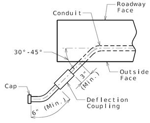 |
 |
| Detail A | Detail B |
| (Use where total movement is not greater than 1½ inches.) | (Use where total movement is greater than 1½ inches.) |
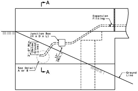 |
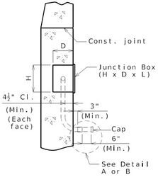 |
| Part Elevation Showing Junction Box in Wing | Section A-A |
| (Use where junction box is in wing only) (Single conduit shown, multiple conduits similar.) |
(Single conduit shown, multiple conduits similar.) |
| Note: 3½” inch clear provides approximately 1½” clearance between the conduit and vertical reinforcing steel on roadway face. This clearance is excessive, but is recommended to keep the clearances to front and back face of barrier similar for ease of construction. |
751.10.5 Approach Slab
Refer to EPG 503 Bridge Approach Slabs for general guidance.
