106.3.2.64 TM-64, Void Detection and Undersealing Verification Testing of Concrete Pavement with a Falling Weight Deflectometer: Difference between revisions
m TM-64 was deleted, per CM. It is no longer valid. |
m Per CM, new TM-64 |
||
| (One intermediate revision by the same user not shown) | |||
| Line 1: | Line 1: | ||
==106.3.2.64.1 Apparatus== | |||
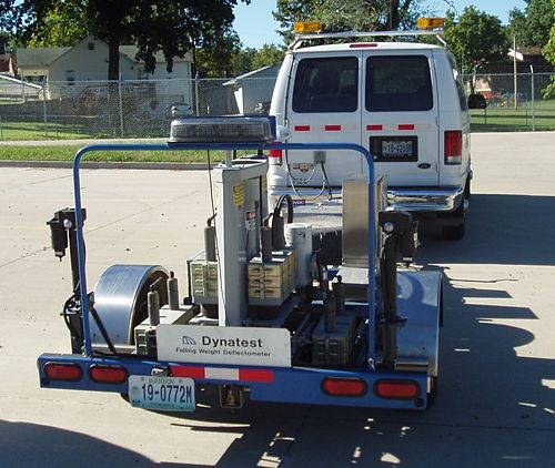
A falling weight deflectometer (FWD) shall be employed for performing void detection testing. The FWD shall have: | |||
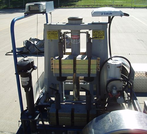
:1) A guided falling weight system capable of generating a peak force of 9000 lbf, | |||
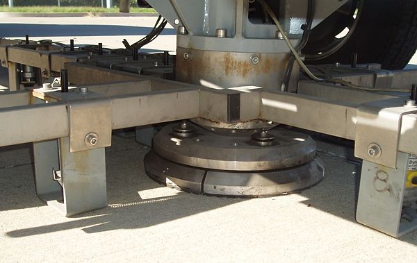
:2) A 12 in. diameter load plate capable of uniformly distributing the falling weight impact force on the pavement surface, | |||
:3) A deflection sensor in the center of the load plate, | |||
:4) A load cell to measure the applied load of each impact, | |||
:5) Data processing and storage equipment to accurately record the peak load with a resolution of 50 lbf or less and peak deflection with a resolution of 0.04 mils or less, | |||
:6) A distance measuring instrument (DMI) or global positioning system (GPS) to record test locations. | |||
The FWD shall have a reference calibration of the load and measurement systems performed in accordance with the manufacturer’s recommendations within one year prior to testing on the MoDOT project. | |||
The FWD shall have a relative calibration of the deflection sensors performed in accordance with the manufacturer’s recommendations within one month prior to testing on the MoDOT project. | |||
[[image:106.3.2.64.1.jpg|center|500px|thumb|<Center>'''Falling Weight Deflectometer'''</center>]] | |||
==106.3.2.64.2 Procedure== | |||
In this test method deflection testing at concrete corner slab joints and cracks serves one of the following two purposes: | |||
:* To identify voids under slabs that require undersealing | |||
:* To verify slabs have been successfully undersealed. | |||
<u>'''Void Detection'''</u> | |||
Deflection testing shall occur when the ambient temperature is ≤ 70º F. The following steps shall be used for void identification under a slab: | |||
:'''Step 1.''' The load plate shall be placed as close as possible to the outside corner of the driving lane approach slab without passing over the joint or crack edge. | |||
[[image:106.3.2.64.2 load.jpg|center|600px|thumb|<Center>'''Load Plate'''</center>]] | |||
:'''Step 2.''' An approximate 9000 lbf shall be applied to the load plate five consecutive times. The first two drops will seat the plate and their deflections will not be counted. The final three drops will be averaged to determine the deflection under the load plate. | |||
[[image:106.3.2.64.2 falling.jpg|center|500px|thumb|<Center>'''Falling Weights'''</center>]] | |||
:'''Step 3.''' The load plate shall then be moved as close as possible to the outside corner of the driving lane leave slab without passing over the joint or crack edge. | |||
:'''Step 4.''' The test will proceed with load drops as in Step 2. | |||
[[image:106.3.2.64.2.jpg|center|800px]] | |||
:'''Step 5.''' The normalized deflection (Δ) for each drop shall be calculated using the following equation: | |||
::::Δ = (D)(9000)/(P) | |||
:where, | |||
:::D = actual peak deflection (mils) | |||
:::P = actual peak load (lbf) | |||
:'''Step 6.''' The differential deflection (DD) shall be calculated using the following equation: | |||
::::DD = Δ<sub>L</sub> - Δ<sub>A</sub> | |||
:where, | |||
:::Δ<sub>L</sub> = average of three normalized deflections on leave side (mils) | |||
:::Δ<sub>A</sub> = average of three normalized deflections on approach side (mils) | |||
:'''Step 7.''' ''The slabs at the test location shall be undersealed if one of the following occurs:'' | |||
:::a. Δ<sub>L</sub> ≥ 20 mils | |||
:::b. DD ≥ 15 mils | |||
<u>'''Undersealing Verification'''</u> | |||
The following steps shall be used for verification of successful undersealing after the undersealing material has reached its recommended set time: | |||
:'''Step 1.''' Steps 1 through 6 from Void Detection shall be conducted. | |||
:'''Step 2.''' ''The slabs at the test location shall be considered successfully undersealed if one of the following occurs:'' | |||
:::a. Δ<sub>L</sub> ≤ 15 mils | |||
:::b. DD ≤ 10 mils | |||
[[Category:106.3.2 Material Inspection Test Methods]] | [[Category:106.3.2 Material Inspection Test Methods]] | ||
Latest revision as of 11:54, 8 October 2013
106.3.2.64.1 Apparatus
A falling weight deflectometer (FWD) shall be employed for performing void detection testing. The FWD shall have:
- 1) A guided falling weight system capable of generating a peak force of 9000 lbf,
- 2) A 12 in. diameter load plate capable of uniformly distributing the falling weight impact force on the pavement surface,
- 3) A deflection sensor in the center of the load plate,
- 4) A load cell to measure the applied load of each impact,
- 5) Data processing and storage equipment to accurately record the peak load with a resolution of 50 lbf or less and peak deflection with a resolution of 0.04 mils or less,
- 6) A distance measuring instrument (DMI) or global positioning system (GPS) to record test locations.
The FWD shall have a reference calibration of the load and measurement systems performed in accordance with the manufacturer’s recommendations within one year prior to testing on the MoDOT project.
The FWD shall have a relative calibration of the deflection sensors performed in accordance with the manufacturer’s recommendations within one month prior to testing on the MoDOT project.

106.3.2.64.2 Procedure
In this test method deflection testing at concrete corner slab joints and cracks serves one of the following two purposes:
- To identify voids under slabs that require undersealing
- To verify slabs have been successfully undersealed.
Void Detection
Deflection testing shall occur when the ambient temperature is ≤ 70º F. The following steps shall be used for void identification under a slab:
- Step 1. The load plate shall be placed as close as possible to the outside corner of the driving lane approach slab without passing over the joint or crack edge.

- Step 2. An approximate 9000 lbf shall be applied to the load plate five consecutive times. The first two drops will seat the plate and their deflections will not be counted. The final three drops will be averaged to determine the deflection under the load plate.

- Step 3. The load plate shall then be moved as close as possible to the outside corner of the driving lane leave slab without passing over the joint or crack edge.
- Step 4. The test will proceed with load drops as in Step 2.

- Step 5. The normalized deflection (Δ) for each drop shall be calculated using the following equation:
- Δ = (D)(9000)/(P)
- where,
- D = actual peak deflection (mils)
- P = actual peak load (lbf)
- Step 6. The differential deflection (DD) shall be calculated using the following equation:
- DD = ΔL - ΔA
- where,
- ΔL = average of three normalized deflections on leave side (mils)
- ΔA = average of three normalized deflections on approach side (mils)
- Step 7. The slabs at the test location shall be undersealed if one of the following occurs:
- a. ΔL ≥ 20 mils
- b. DD ≥ 15 mils
Undersealing Verification
The following steps shall be used for verification of successful undersealing after the undersealing material has reached its recommended set time:
- Step 1. Steps 1 through 6 from Void Detection shall be conducted.
- Step 2. The slabs at the test location shall be considered successfully undersealed if one of the following occurs:
- a. ΔL ≤ 15 mils
- b. DD ≤ 10 mils