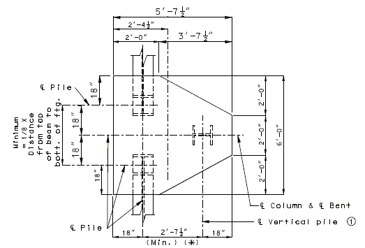
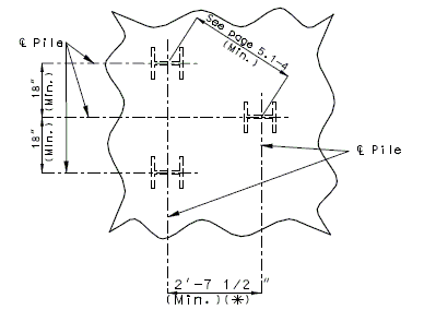
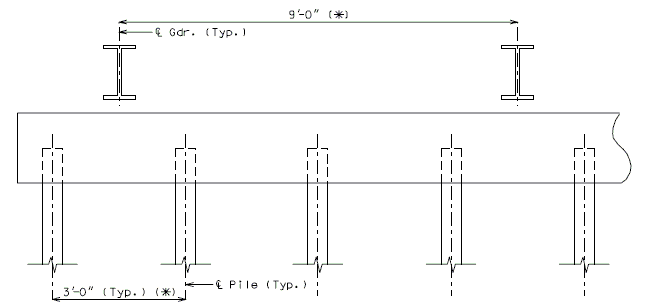
751.40 LFD Widening and Repair: Difference between revisions
m →751.40.2.4 Deck Repair and Filled Joints: Per Bridge, replaced link with updated table that more accurately portrayed the available drawings |
updated per RR3945 |
||
| (70 intermediate revisions by 3 users not shown) | |||
| Line 1: | Line 1: | ||
<div style="float: right; width: 500px; margin-top: 5px; margin-left: 30px; margin-bottom: 30px;">__TOC__</div> | |||
== 751.40.1 General == | == 751.40.1 General == | ||
=== 751.40.1.1 Widening and Repair of Existing Structures === | === 751.40.1.1 Widening and Repair of Existing Structures === | ||
The Federal Highway Administration and the States have established a goal that the LRFD standards be used on all new bridge designs after October 2007. For modification to existing structures and with the approval of the Structural Project Manager or Structural Liaison Engineer, the LRFD Specifications or the specifications which were used for the original design, may be used by the designer. | The Federal Highway Administration and the States have established a goal that the LRFD standards be used on all new bridge designs after October 2007. For modification to existing structures and with the approval of the Structural Project Manager or Structural Liaison Engineer, the LRFD Specifications or the specifications which were used for the original design, may be used by the designer. | ||
==751.40.2 | ==751.40.2 Deck Treatments== | ||
===751.40.2.1 Resurfacing=== | ===751.40.2.1 Resurfacing=== | ||
{| style="text-align: center; margin: 0 auto;" | |||
|- | |||
| [[Image:751.40_Resurfacing_Plan.gif|center]] | |||
|- | |||
| <big>'''PLAN'''</big> | |||
|} | |||
< | {| style="text-align: center; margin: 0 auto;" | ||
|- | |||
| [[Image:751.40_Resurfacing_Section_Thru_Roadway.gif|center]] | |||
|- | |||
| <big>'''SECTION THRU ROADWAY'''</big> | |||
|} | |||
Place the following notes on plans. | |||
: The existing asphaltic concrete surface shall be removed to a uniform grade line * below the existing control grade line as noted. | |||
: Resurface with * Asphaltic Concrete. | |||
: <nowiki>*</nowiki> Depth of asphaltic concrete as specified in the Bridge Memorandum. | |||
===751.40.2.2 Special Repair Zones=== | |||
The following order of repair zones shall be used for the deck repair on continuous concrete structures. | |||
'''Hydro Demolition Projects (Case 1 and 2)''' | |||
Conventional deck repair required in the areas designated as special repair zones shall be completed before demolition in alphabetical sequence beginning with Zone A. Zones with the same letter designation may be repaired at the same time. | |||
Any deck repair in areas not designated as a special repair zone shall be completed after hydro demolition. Case 1 is primarily monolithic deck repair after hydro demolition. Case 2 is primarily conventional deck repair after hydro demolition. | |||
: | Note: | ||
:- Case 1 shall not be used for polyester polymer and low slump concrete wearing surfaces (too stiff for monolithic repairs). | |||
:- Conventional deck repair is required with void tube replacement after hydro demolition with both Case 1 and Case 2. | |||
:- If an excessive number of zones are required at any bent, see the Structural Project Manager or Structural Liaison Engineer. | |||
:- Consider combining zones if the length of a zone in the longitudinal direction of the bridge is less than 24 inches. | |||
:( | {| style="text-align: center; margin: 0 auto;" | ||
|- | |||
| [[image:751.40.2.2_hydro_part-plan.png|center|750px]] | |||
|- | |||
| <big>'''PART PLAN OF SLAB SHOWING REPAIR ZONES (A, B, C and D)'''</big> | |||
|} | |||
:::(1) Development Length. | |||
:::See [[751.50_Standard_Detailing_Notes|EPG 751.50 Standard Detailing Notes]] for appropriate notes. | |||
'''Non-Hydro Demolition Projects''' | |||
Any deck repair in areas not designated as a special repair zone shall be completed prior to work in Zone A. Zones with the same letter designation may be repaired at the same time. | |||
Note: | |||
:- If an excessive number of zones are required at any bent, see the Structural Project Manager or Structural Liaison Engineer. | |||
:- Consider combining zones if the length of a zone in the longitudinal direction of the bridge is less than 24 inches. | |||
{| style="text-align: center; margin: 0 auto;" | |||
|- | |||
| [[image:751.40.2.2_nonhydro_part-plan.png|center|750px]] | |||
|- | |||
| <big>'''PART PLAN OF SLAB SHOWING REPAIR ZONES (A, B and C)'''</big> | |||
|} | |||
:::(1) Development Length. | |||
:::See [[751.50_Standard_Detailing_Notes|EPG 751.50 Standard Detailing Notes]] for appropriate notes. | |||
===751.40.2.3 Deck Repair and Filled Joints=== | |||
<div style="float: right; margin-top: 5px; margin-bottom: 5px; padding: 5px; text-align:center; border: 1px solid black; border-radius:5px; box-shadow:5px 5px 5px #888888"> | |||
'''Bridge Deck, Repair'''</br> | |||
[https://spexternal.modot.mo.gov/sites/cm/CORDT/RDT02002.pdf Report 2002]</br> | |||
'''See also:''' [https://www.modot.org/research-publications Research Publications] | |||
</div> | |||
{| border="1" class="wikitable" style="margin: 0 auto; text-align: center" | |||
|+ | |||
| style="background:#BEBEBE" | '''[https://www.modot.org/bridge-standard-drawings Bridge Standard Drawings]''' | |||
|- | |||
| Rehabilitation, Surfacing & Widening – RHB; Deck Rehab (Deck Repair and Wearing Surface Details) | |||
|} | |||
===751.40.2.4 Wearing Surfaces=== | |||
'''Replacement of Typical Expansion Joint Systems (Strip Seal Shown, Other Systems Similar)''' | |||
[[image:751.40.3.1 wearing surfaces.jpg|center|650px]] | |||
When concrete is removed and armor is replaced, see [[751.13 Expansion Joint Systems|EPG 751.13 Expansion Joint Systems]] for the appropriate expansion joint system details and [[751.50 Standard Detailing Notes#H5. Expansion Joint Systems|EPG 751.50 H5]] for the appropriate notes. | |||
For chip seals and polymer wearing surfaces, see [[751.50 Standard Detailing Notes#I1. General|EPG 751.50 I1]] for the appropriate notes. | |||
'''Elastomeric Expansion Joint System''' | |||
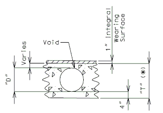
When a thick wearing surface (low slump, latex, silica fume, CSA cement, steel fiber reinforced, asphaltic) is used, the elastomeric joint must be replace by another type of expansion joint system. | |||
[[image:751.40.3.1 elastomeric.jpg|center|375px]] | |||
'''Flat Plate Expansion Joint System ''' | |||
[[image:751.40.3.1 flat thick.jpg|center|575px]] | |||
::: '''*''' When this dimension exceeds 3" and a concrete wearing surface is used, tack weld a one inch bar chair to the plate for each 3" of plate to be covered by the wearing surface. | |||
::: '''**''' Scarify existing slab. See the Bridge Memorandum for the minimum depth of scarification. Scarification not required for asphaltic concrete wearing surface. | |||
::: Note: See standard plans for Steel Dams at Expansion Joints. | |||
[[image:751.40.3.1 flat thin.jpg|center|400px]] | |||
===751.40.2.5 Edge Treatments=== | |||
====751.40.2.5.1 Epoxy Coating==== | |||
{| style="text-align: center; margin: 0 auto;" | |||
{|style=" | |||
|- | |- | ||
|[ | | [[Image:751.40.3.1 latex section.jpg|center|540px]] | ||
|- | |- | ||
|''' | | <big>'''TYPICAL SECTION OF EXISTING CURB<br/>OUTLET SHOWING LIMITS OF EPOXY COATING'''</big> | ||
|} | |} | ||
::: Note: | |||
::: '''*''' Dimension to edge of girder or stringer ±. For bridges that do not have girders or stringers use 2'-6", except that if with thrie beam rail, then use 4'-0". | |||
::: Consult with Structural Project Manager or Liaison for making work incidental to another item or use of pay item "Cleaning and Epoxy Coating". | |||
{| | {| style="text-align: center; margin: 0 auto;" | ||
|- | |- | ||
| | | [[Image:751.40.3.1 latex elevation.jpg|440px]] | ||
|- | |- | ||
| | | <big>'''TYPICAL ELEVATION OF EXISTING CURB<br/>OUTLET SHOWING LIMITS OF EPOXY COATING'''</big><br/>(Wearing surface not shown for clarity) | ||
|} | |} | ||
===751.40.2.5 | ====751.40.2.5.2 Edge Repair==== | ||
If slab edge repair is specified on the Bridge Memorandum when the barrier or railing is not removed or when full depth repair is not a pay item, the following detail shall be provided. | |||
{| style="text-align: center; margin: 0 auto;" | |||
|- | |||
| [[Image:751.40_Concrete_Wearing_Surface_Slab_Edge_Repair_(Concrete_Edge_Repair)_no_1.gif|center]] | |||
|- | |||
| <big>'''CONCRETE EDGE REPAIR'''</big> | |||
|} | |||
:::If the barrier or railing is removed when full depth repair and slab edge repair are pay items, the following detail shall be provided. | |||
| | {| style="text-align: center; margin: 0 auto;" | ||
|- | |- | ||
| | | [[Image:751.40_Concrete_Wearing_Surface_Slab_Edge_Repair_(Concrete_Edge_Repair)_no_1.gif|center]] | ||
|- | |- | ||
| | | <big>'''CONCRETE EDGE REPAIR'''</big> | ||
|} | |} | ||
::: '''*''' If the dimension exceeds 4 inches, the repair extending to the edge of slab will be paid for as Full Depth Repair. | |||
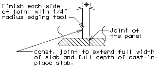
===751.40.2.6 Longitudinal Joints=== | |||
===751.40. | |||
'''REPLACEMENT OF EXISTING EXPANSION DEVICE''' | '''REPLACEMENT OF EXISTING EXPANSION DEVICE''' | ||
'''MEDIAN BARRIER ''' | |||
{| style="text-align: center; margin: 0 auto;" | |||
|- | |||
| [[Image:751.40.2.6_section_thru_barrier.jpg|center|400px]] | |||
|- | |||
| <big>'''SECTION THRU BARRIER'''</big> | |||
|} | |||
{| style="text-align: center; margin: 0 auto;" | |||
|- | |||
| [[Image:751.40.2.6_detail_A.jpg|center|400px]] | |||
|- | |||
| <big>'''DETAIL A'''</big> | |||
|} | |||
::: (1) May be cast vertical and saw cut to slant. | |||
::: * Latex Concrete Wearing Surface = 1-3/4".<br/>Low Slump Concrete Wearing Surface = 2-1/4". | |||
::: ** Cut minimum 1/2" support notch (rough finish). Remove any existing compression seal. | |||
===751.40.2.7 Temporary Traffic Control Device=== | |||
Show Barrier as per district recommendation. Typically Barrier is shown when structure is on interstate and/or the rail is being removed. Otherwise, show the dimension lines with 2'-0" dimension. | |||
[[image:751.40.2.5.jpg|center|700px]] | |||
::: '''*''' If this dimension is less than 3 feet, the temporary concrete traffic barrier shall be attached with tie-down straps, with the approval of the Structural Project Manager or Structural Liaison Engineer. Where lateral deflection cannot be tolerated, the temporary concrete traffic barrier shall be attached with the bolt through deck detail (to be used only on existing decks). See [[617.1 Temporary Traffic Barriers|EPG 617.1 Temporary Traffic Barriers]] and [[751.1 Preliminary Design#751.1.2.12 Temporary Barriers|EPG 751.1.2.12 Temporary Barriers]]. | |||
::: '''**''' Where slab removal represents small and discontinuous openings in the deck along the bridge length (e.g. expansion device replacement) use of either a flat steel plate, a 22 ½” temporary traffic control device or a temporary concrete traffic barrier may be more appropriate. Consult with the Structural Project Manager or Structural Liaison Engineer. | |||
==751.40.3 Substructure Repair== | |||
===751.40.3.1 Formed and Unformed Repair Areas=== | |||
{| style="text-align: center; margin: 0 auto;" | |||
|- | |||
| [[Image:751.40.3.1_elev_int_bent.png|center|700px]] | |||
|- | |||
| <big>'''Elevation of Int. Bent'''</big> | |||
|} | |||
{| style="text-align: center; margin: 0 auto;" | |||
|- | |||
| [[Image:751.40.3.1_sec_through_end_bent.png|center|400px]] | |||
|- | |||
| <big>'''Section through End Bent'''</big> | |||
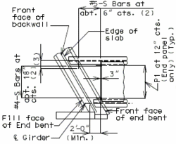
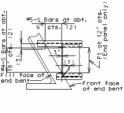
|} | |||
===751.40.3.2 Bent Cap Shear Strengthening using FRP Wrap=== | |||
{| border="1" class="wikitable" style="margin: 0 auto; text-align: center" | |||
|+ | |||
| style="background:#BEBEBE" | '''[https://www.modot.org/bridge-standard-drawings Bridge Standard Drawings]''' | |||
|- | |||
| Rehabilitation, Surfacing & Widening; Fiber Reinf. Polymer (FRP) Wrap for Bent Cap Strengthening [RHB08] | |||
|} | |||
Fiber Reinforced Polymer (FRP) wrap may be used for Bent Cap Shear Strengthening. | |||
'''When to strengthen:''' When increased shear loading on an existing bent cap is required and a structural analysis shows insufficient bent cap shear resistance, bent cap shear strengthening is an option. An example of when strengthening a bent cap may be required: removing existing girder hinges and making girders continuous will draw significantly more force to the adjacent bent. An example of when strengthening a bent cap is not required: redecking a bridge where analysis shows that the existing bent cap cannot meet capacity for an HS20 truck loading, and the new deck is similar to the old deck and the existing beam is in good shape. | |||
''' | '''How to strengthen:''' Using FRP systems for shear strengthening follows from the guidelines set forth in ''NCHRP Report 678, Design of FRP System for Strengthening Concrete Girders in Shear''. The method of strengthening, using either discrete strips or continuous sheets, is made optional for the contractor in accordance with ''NCHRP Report 678''. A Bridge Standard Drawing and Bridge Special Provision have been prepared for including this work on jobs. They can be revised to specify a preferred method of strengthening if desired, strips or continuous sheet. | ||
'''What condition of existing bent cap required for strengthening:''' If a cap is in poor shape where replacement should be considered, FRP should not be used. Otherwise, the cap beam can be repaired before applying FRP. Perform a minimum load check using (1.1DL + 0.75(LL+I))'''*''' on the existing cap beam to prevent catastrophic failure of the beam if the FRP fails (''ACI 440.2R, Guide for the Design and Construction of Externally Bonded FRP, Sections 9.2 and 9.3.3''). If the factored shear resistance of the cap beam is insufficient for meeting the factored minimum load check, then FRP strengthening should not be used. | |||
:: '''*''' ACI 440.2R: ''Guide for the Design and Construction of Externally Bonded FRP'' | |||
'''Design force (net shear strength loading):''' Strengthening a bent cap requires determining the net factored shear loading that the cap beam must carry in excess of its unstrengthened factored shear capacity, or resistance. The FRP system is then designed by the manufacturer to meet this net factored shear load, or design force. The design force for a bent cap strengthening is calculated considering AASHTO LFD where the factored load is the standard Load Factor Group I load case. To determine design force that the FRP must carry alone, the factored strength of the bent cap, which is 0.85 x nominal strength according to LFD design, is subtracted out to give the net factored shear load that the FRP must resist by itself. ''NCHRP Report 678'' is referenced in the special provisions as guidelines for the contractor and the manufacturer to follow. The report and its examples use AAHTO LRFD. <u>Regardless, the load factor case is given and it is left to the manufacturer to provide for a satisfactory factor of safety based on their FRP system.</u> | |||
Other References: | |||
:: '''*''' ACI 201.1R: ''Guide for Making a Condition Survey of Concrete in Service'' | |||
:: '''*''' ACI 224.1R: ''Causes, Evaluation, and Repair of Cracks in Concrete'' | |||
:: '''*''' ACI 364.1R-94: ''Guide for Evaluation of Concrete Structures Prior to Rehabilitation'' | |||
:: '''*''' ACI 440.2R-08: ''Guide for the Design and Construction of Externally Bonded FRP Systems for Strengthening Concrete Structures'' | |||
:: '''*''' ACI 503R: ''Use of Epoxy Compounds with Concrete'' | |||
:: '''*''' ACI 546R: ''Concrete Repair Guide'' | |||
:: '''*''' International Concrete Repair Institute (ICI) ICI 03730: ''Guide for Surface Preparation for the Repair of Deteriorated Concrete Resulting from Reinforcing Steel Corrosion'' | |||
:: '''*''' International Concrete Repair Institute (ICI) ICI 03733: ''Guide for Selecting and Specifying Materials for Repairs of Concrete Surfaces'' | |||
:: '''*''' NCHRP Report 609: ''Recommended Construction Specifications Process Control Manual for Repair and Retrofit of Concrete Structures Using Bonded FRP Composites'' | |||
===751.40.3.3 Steel HP Pile Maintenance and Repair=== | |||
'''Maintenance/Repair Guidelines''' | |||
Piles are primary structural members and are compressively loaded all the time which makes it important to safely inspect, maintain and repair them if necessary. Pile inspection will require an assessment of pile performance by looking for pile deterioration and measuring pile section loss in order to determine the level of pile maintenance/repair required. The following schedule may be used for selecting the level of maintenance/repair required: | |||
{| class="wikitable" style="cellpadding="5" align="center" | |||
|- | |||
! Pile Percent Section Loss !! Method'''*''' !! Level | |||
|- | |||
| 0% through 25% || Clean and recoat existing piles || Maintenance | |||
|- | |||
| >25% through 40% || Encasement of deteriorated section || Maintenance | |||
|- | |||
| >40% through 75% or holes in any element or local buckling of any element || Plating ** of deteriorated section OR replacement *** of section (splicing), AND encasement of the repaired section || Repair | |||
|- | |||
| >75% || Contact the Bridge Division || Repair | |||
|- | |||
| colspan="3" | '''*''' Method may also include cleaning and recoating all exposed piles, and cleaning and recoating all remaining exposed pile sections after encasement and/or repair. | |||
|- | |||
| colspan="3" | '''**''' Plating can be for both flanges only, web only or both flanges and web. Overall symmetry of the pile cross-section shall be maintained when plating. | |||
|- | |||
| colspan="3" | '''***''' Based on additional factors other than just the percent of pile section loss, a replacement pile section (splicing) may be considered. Minimizing or eliminating traffic loading, adding falsework or just having support conditions such as integral bents (where both the pile cap beam and the superstructure concrete diaphragm are connected by more than just dowel bars – see bridge plans) can help to determine the method of repair. A replacement pile section can be coated or galvanized. See Structural Project Manager. | |||
|} | |||
'''Estimating Pile Percent Section Loss in the Field''' | |||
Quantifying pile section loss can be inexact. To encourage uniform application of the maintenance/repair guidelines, the following procedure is recommended: | |||
:1. Pile section loss should be determined using a thickness meter. | |||
:2. Remove deteriorated material and clean pile for measurement. | |||
:3. At any point along a pile (cross-section) where there are three elements to be considered independently, e.g. two flanges and a web. | |||
:4. Estimate the actual cross-section area of each element at its most deteriorated point along the length of pile. Using the thickness meter, measure the thickness at several points along a horizontal line across the element. From this data, estimate the actual cross-section area of each element. | |||
:5. The fraction of section remaining (PSR) is the actual cross-section area of each element at its most deteriorated point along the length of pile divided by the original area of same element. | |||
:6. Percent section loss is 100(1 – PSR) for each element. | |||
:7. The greatest PSR dictates the maintenance/repair method. | |||
:8. Examine continuity at flange/web intersections. Section loss along these intersections along the length of pile of more than 6 linear inches should be repaired using encasement as either the only method or part of plating/replacing repair method regardless of a low percent section loss. | |||
:9. Interference from cross bracing at pile sections to be repaired will need special consideration not detailed on the standard drawings. | |||
{| class="wikitable" style="margin: 0 auto; text-align: center" | |||
|+ | |||
| style="background:#BEBEBE" | '''[https://www.modot.org/bridge-standard-drawings Bridge Standard Drawings]''' | |||
|- | |||
| Rehabilitation, Surfacing & Widening – RHB; Steel HP Pile Maintenance and Repair | |||
|} | |||
Additional types of maintenance and repairs may be considered which include but are not limited to: | |||
:* Zinc tape coating | |||
:* FRP strengthening | |||
:* Corrosion inhibitor | |||
==751.40.4 Barriers and Railings== | |||
===751.40.4.1 End Post Modification for 12-inch Vertical Barrier (Safe & Sound Bridges)=== | |||
The 12-inch vertical barrier requires modification to allow attachment of the transition for the Midwest Guardrail System. | |||
{| | {| class="wikitable" style="margin: 0 auto; text-align: center" | ||
|+ | |||
| | | style="background:#BEBEBE" | '''[https://www.modot.org/bridge-standard-drawings Bridge Standard Drawings]''' | ||
|- | |- | ||
| | | Barrier End Modifications – BEM & CBO/Barrier End Modification – BEM | ||
|} | |} | ||
===751.40.4.2 Replacement of Existing Type B Barrier Using Anchor Systems=== | |||
'''NEW BARRIER ON SLAB''' | |||
{| style="text-align: center; margin: 0 auto;" | |||
|- | |||
| [[Image:751.40_Replacement_of_Existing_Curb_(Safety_Barrier_Curb_on_Slab)_Section_Thru_Curb.gif]] | |||
|- | |||
| '''SECTION THRU BARRIER''' | |||
|} | |||
{| style="text-align: center; margin: 0 auto;" | |||
|- | |||
| [[Image:751.40_Replacement_of_Existing_Curb_(Safety_Barrier_Curb_on_Slab)_Section_Thru_Curb_Optional_Anchoring_System.gif]] | |||
|- | |||
| '''SECTION THRU BARRIER'''<br/>'''(OPTIONAL ANCHORING SYSTEM)''' | |||
|- | |||
| See [[751.50 Standard Detailing Notes#I2. Resin & Cone Anchors|EPG 751.50 I2. Resin & Cone Anchors]] for appropriate notes. | |||
|} | |||
'''NEW BARRIER ON WING''' | |||
''' | {| style="text-align: center; margin: 0 auto;" | ||
|- | |||
| [[Image:751.40_Replacement_of_Existing_Curb_(Safety_Barrier_Curb_on_Wing)_Section_Thru_Curb.gif]] | |||
|- | |||
| '''SECTION THRU BARRIER(*)''' | |||
|} | |||
{| style="text-align: center; margin: 0 auto;" | |||
|- | |||
| [[Image:751.40_Replacement_of_Existing_Curb_(Safety_Barrier_Curb_on_Wing)_Section_Thru_Curb_Optional_Anchoring_System.gif]] | |||
|- | |||
| '''SECTION THRU BARRIER(*)'''<br/>'''(OPTIONAL ANCHORING SYSTEM)''' | |||
|} | |||
:Note: See [[751.50 Standard Detailing Notes#I2. Resin & Cone Anchors|EPG 751.50 I2. Resin & Cone Anchors]] for appropriate notes. For details not shown, see [[751.12 Barriers, Railings, Curbs and Fences|EPG 751.12 Barriers, Railings, Curbs and Fences]]. | |||
'''REPLACEMENT OF EXISTING BARRIER AT END OF WING USING ANCHOR SYSTEMS''' | |||
'''INTEGRAL END BENTS''' | |||
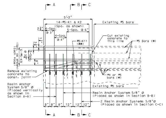
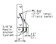
Note: | {| style="text-align: center; margin: 0 auto;" | ||
|- | |||
| style="text-align:left; width: 250px" | (*)Extend existing horizontal bars 2'-3" into new concrete.</br>(**) Fit bar to follow transition face of barrier.</br>Note: For details of guardrail attachment, see barrier standard drawings. || rowspan="2" | [[Image:751.40_Replacement_of_Existing_Curb_at_End_of_Wing_(Integral_End_Bents)_Part_Elevation.gif]] | |||
|- | |||
| [[Image:751.40_Replacement_of_Existing_Curb_at_End_of_Wing_(Integral_End_Bents)_Anchor_Systems_at_Section_CC.gif]] | |||
|- | |||
| '''ANCHOR SYSTEMS AT SECTION C-C''' || '''PART ELEVATION''' | |||
|- | |||
|} | |||
{| style="text-align: center; margin: 0 auto;" | |||
|- | |||
| [[Image:751.40_Replacement_of_Existing_Curb_at_End_of_Wing_(Integral_End_Bents)_Section_AA.gif]] || [[Image:751.40_Replacement_of_Existing_Curb_at_End_of_Wing_(Integral_End_Bents)_Section_BB.gif]] || [[Image:751.40_Replacement_of_Existing_Curb_at_End_of_Wing_(Integral_End_Bents)_Section_CC.gif]] | |||
|- | |||
| '''SECTION A-A''' || '''SECTION B-B''' || '''SECTION C-C''' | |||
|- | |||
|} | |||
'''REPLACEMENT OF EXISTING BARRIER AT END OF WING USING ANCHOR SYSTEMS''' | |||
'''NON-INTEGRAL END BENTS''' | |||
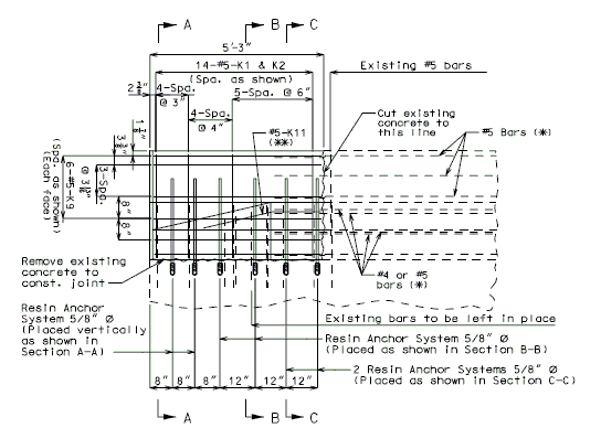
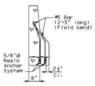
{| style="text-align: center; margin: 0 auto;" | |||
|- | |||
| style="text-align:left; width: 250px" | (*)Extend existing horizontal bars 2'-3" into new concrete.</br>(**) Fit bar to follow transition face of barrier.</br>Note: For details of guardrail attachment, see barrier standard drawings. || rowspan="2" | [[Image:751.40_Replacement_of_Existing_Curb_at_End_of_Wing_(Non-Integral_End_Bents)_Part_Elevation.gif]] | |||
|- | |||
| [[Image:751.40_Replacement_of_Existing_Curb_at_End_of_Wing_(Non-Integral_End_Bents)_Anchor_Systems_at_Section_CC.gif]] | |||
|- | |||
| '''ANCHOR SYSTEMS AT SECTION C-C''' || '''PART ELEVATION''' | |||
|- | |||
|} | |||
{| style="text-align: center; margin: 0 auto;" | |||
|- | |||
| [[Image:751.40_Replacement_of_Existing_Curb_at_End_of_Wing_(Non-Integral_End_Bents)_Section_AA.gif]] || [[Image:751.40_Replacement_of_Existing_Curb_at_End_of_Wing_(Non-Integral_End_Bents)_Section_BB.gif]] | [[Image:751.40_Replacement_of_Existing_Curb_at_End_of_Wing_(Non-Integral_End_Bents)_Section_CC.gif]] | |||
|- | |||
| '''SECTION A-A''' || '''SECTION B-B''' || '''SECTION C-C''' | |||
|- | |||
|} | |||
===751.40.4.3 Replacement of Existing Rail with Thrie Beam Rail=== | |||
As a matter of policy, blockouts for thrie beam railings are required while FHWA does show similar systems without blockouts as NCHRP 350 approved. See the Structural Project Manager (SPM) or the Structural Liaison Engineer (SLE), if practical, to omit blockout. A design exception shall be required. Blockouts shall always be required on major routes. | |||
There are four systems for use on state routes. In these four systems the connection design load used is 1.5 times plastic moment capacity (Mp) of W6 x 20 Post. The vertical clearance of System 3 shall be checked due to the obtruding lower connection. | |||
{| class="wikitable" style="margin: 0 auto; text-align: center" | |||
|+ | |||
| style="background:#BEBEBE" | '''[https://www.modot.org/bridge-standard-drawings Bridge Standard Drawings]''' | |||
|- | |||
| Thrie Beam Rails - THRIE | |||
|} | |||
===751.40.4.4 End Treatment Using Thrie Beam Rail=== | |||
[[image:751.40.4.4.jpg|center|700px]] | |||
[[image:751.40.4.4 clearance.jpg|center|700px]] | |||
Guidance for Design: | |||
:Adequate clearance to first post off bridge shall be required. (See also [https://www.modot.org/media/16893 Standard Plan 617.10] for new bridges.) | |||
===751.40.4.5 Curb Blockouts=== | |||
See [[751.1_Preliminary_Design#751.1.3.4_Barrier_or_Railing_Type.2C_Height_and_Guidelines_for_Curb_Blockouts | EPG 751.1.3.4 Barrier or Railing Type, Height and Guidelines for Curb Blockouts]] for usage guidance. | |||
{| class="wikitable" style="margin: 0 auto; text-align: center" | |||
|+ | |||
| style="background:#BEBEBE" | '''[https://www.modot.org/bridge-standard-drawings Bridge Standard Drawings]''' | |||
|- | |||
| Barrier Modifications – BEM & CBO/Curb Blockouts - CBO | |||
|} | |||
==751.40.5 Drainage== | |||
===751.40. | ===751.40.5.1 Structure with Wearing Surface Slab Drains - Details=== | ||
''' | '''Two material options may be used for slab drains: | ||
''' | :'''1. Steel Slab Drains''' and inserts are only shown in the following details. | ||
:'''2. Fiberglass Reinforced Polymer (FRP)''' drains may be used with the approval of the Structural Project Manager or Structural Liaison Engineer. See [https://epg.modot.org/index.php?title=751.10_General_Superstructure#751.10.3.2.1_New_Structure_Without_Wearing_Surface_Slab_Drains_-_Details EPG 751.10.3.2.1 New Structure Without Wearing Surface Slab Drains - Details] for guidance and details of FRP drains on new structures as an aid. | |||
:A positive mechanical connection must be used for attaching FRP drains to either existing steel drains or to new FRP inserts since welding cannot be used as is shown in the following details for steel drains. For example, using at least four bolt-through connectors (one per side) from new FRP drains into a new wearing surface or an existing steel drain, or using an epoxy adhesive in conjunction with at least two bolt-through connectors is required. It has been shown that using a more viscous epoxy or anchoring gel is beneficial in order to avoid dripping during placement. Using epoxy adhesive or an anchoring gel by itself is not acceptable. | |||
:FRP drain may not fit exactly to the inside or to the outside of existing steel drain. The looseness of fit can be addressed by considering a combination of attachment details like mechanical connectors (to existing slab drain) plus either a viscous epoxy adhesive or a positive attachment to an exterior girder depending on the length of the slab drain extension. | |||
'''For new wearing surface over new slab, note on plans:''' | |||
:Piece "A" shall be cast in the concrete slab. Prior to placement of wearing surface, piece "B" shall be inserted into piece "A". | |||
'''FOR STRUCTURE WITH WEARING SURFACE'''<br/>'''(GIRDER DEPTH LESS THAN 48")''' | |||
<center>[[Image:751. | <center>[[Image:751.40_Slab_Drain_Details_(Girder_Depth_Less_than_48_in.)_Part_Elev_of_Slab_at_Drain.gif]]</center> | ||
< | <center>'''PART ELEVATION OF SLAB AT DRAIN'''</center> | ||
<center>[[Image:751.40_Slab_Drain_Details_(Girder_Depth_Less_than_48_in.)_Elev_of_Drain.gif]]</center> | |||
<center>'''ELEVATION OF DRAIN'''</center> | |||
== | {|border="0" align="center" | ||
|*||Deck thickness minus 1/8" minus the depth of the scarification. | |||
| | |||
| | |||
|- | |- | ||
| | |**||Do not include the depth of the scarification. | ||
|} | |} | ||
| |||
| |||
| |||
<center>[[Image:751.40_Slab_Drain_Details_(Girder_Depth_Less_than_48_in.)_Plan_of_Drain.gif]]</center> | |||
<center>'''PLAN OF DRAIN'''</center> | |||
''' | '''FOR STRUCTURE WITH WEARING SURFACE'''<br/>'''(GIRDER DEPTH 48" AND OVER)''' | ||
{|border="0" cellpadding=" | {|border="0" cellpadding="5" align="center" style="text-align:center" | ||
|[[Image:751. | |rowspan="3"|[[Image:751.40_Slab_Drain_Details_(Girder_Depth_48_in._and_over)_Part_Elevation_of_Slab_at_Drain.gif]] | ||
|[[Image:751. | |[[Image:751.40_Slab_Drain_Details_(Girder_Depth_48_in._and_over)_Elev_of_Drain.gif]] | ||
|- | |- | ||
|''' | |'''ELEVATION OF DRAIN'''<!--cell a occupied by [[Image:751.40_Slab_Drain_Details_(Girder_Depth_48_in._and_over)_Part_Elevation_of_Slab_at_Drain.gif]]--> | ||
|- | |- | ||
| | |[[Image:751.40_Slab_Drain_Details_(Girder_Depth_48_in._and_over)_Plan_of_Drain.gif]]<!--cell a occupied by [[Image:751.40_Slab_Drain_Details_(Girder_Depth_48_in._and_over)_Part_Elevation_of_Slab_at_Drain.gif]]--> | ||
|- | |- | ||
| | |'''PART ELEVATION OF SLAB AT DRAIN'''||'''PLAN OF DRAIN''' | ||
|} | |} | ||
::{|border="0" | |||
|valign="top"|*||If dimension is less than 1", drains shall be placed parallel to roadway. Otherwise, place drains transverse to roadway. | |||
|- | |||
| | |valign="top"|**||Do not include the depth of the scarification. | ||
|- | |||
|valign="top"|***||Deck thickness minus 1/8" minus the depth of the scarification. | |||
|} | |} | ||
{|border="0" align="center" style="text-align:center" | |||
|colspan="2"|[[Image:751.40_Slab_Drain_Details_(Girder_Depth_48_in._and_over)_Part_Plans_Showing_Bracket_Assembly.gif]] | |||
|[[Image:751. | |||
|- | |- | ||
|''' | |'''DRAIN TRANSVERSE TO ROADWAY'''||'''DRAIN PARALLEL TO ROADWAY''' | ||
|- | |- | ||
| | | | ||
|- | |- | ||
|colspan="2"|''' | |colspan="2"|'''PART PLANS SHOWING BRACKET ASSEMBLY''' | ||
|} | |} | ||
''' | '''FOR STRUCTURE WITH WEARING SURFACE'''<BR/>'''(CONTINUOUS CONCRETE STRUCTURES)''' | ||
<center>[[Image:751. | <center>[[Image:751.40_Slab_Drain_Details_(Continuous_Concrete_Structures)_Part_Section_Near_Drain.gif]]</center> | ||
<center>'''SECTION | <center>'''PART SECTION NEAR DRAIN'''</center> | ||
<center>[[Image:751. | <center>[[Image:751.40 Slab Drain Details (Continuous Concrete Structures) Elevation of Drain.gif]]</center> | ||
<center>''' | <center>'''ELEVATION OF DRAIN'''</center> | ||
<center>[[Image:751.40_Slab_Drain_Details_(Continuous_Concrete_Structures)_Plan_of_Drain.gif]]</center> | |||
''' | <center>'''PLAN OF DRAIN'''</center> | ||
{|border="0" align="center" | |||
|*||Deck thickness minus 1/8" minus the depth of the scarification. | |||
|- | |||
|**||Do not include the depth of scarification. | |||
|} | |||
'''FOR STRUCTURE WITH WEARING SURFACE'''<BR/>'''(VARIABLE DEPTH GIRDERS)''' | |||
<center>[[Image:751. | |||
<center>[[Image:751.40_Slab_Drain_Details_(Variable_Depth_Girders)_Part_Elevation_of_Slab_at_Drain.gif]]</center> | |||
<center>''' | <center>'''PART ELEVATION OF SLAB AT DRAIN'''</center> | ||
Note: | Note: For variable depth girders with drains in deeper section, let the deeper section control and use throughout the structure. | ||
<center>[[Image:751.40_Slab_Drain_Details_(Variable_Depth_Girders)_Typ_Section_Straight_Drain.gif]]</center> | |||
<center>'''TYPICAL SECTION STRAIGHT DRAIN'''</center> | |||
===751.40.5.2 Structure with Wearing Surface Round Slab Drains - Details=== | |||
'''FOR STRUCTURE WITH WEARING SURFACE'''<BR/>'''MISCELLANEOUS DETAILS - ROUND DRAINS''' | |||
FRP round drains may be used optionally unless otherwise specified. See [https://epg.modot.org/index.php?title=751.10_General_Superstructure#751.10.3_Bridge_Deck_Drainage_-_Slab_Drains EPG 751.10.3 Bridge Deck Drainage – Slab Drains] for guidance and details as an aid. Specify nominal pipe size as needed referencing ASTM D2996. Specify outer diameter based on nominal pipe size necessary for drainage for coring the correct size hole in deck. | |||
Note: See EPG 751.10.3 Bridge Deck Drainage – Slab Drain for slab drain spacing. | |||
{|border="0" align="center" style="text-align:center" | {|border="0" align="center" style="text-align:center" | ||
|[[image:751.40.5.2 typical.jpg|center|275px]] | |||
|[[ | |[[image:751.40.5.2 section.jpg|center|250px]] | ||
|[[ | |||
|- | |- | ||
| | |'''TYPICAL PART PLAN'''||'''SECTION SHOWING BRACKET ASSEMBLY''' | ||
|} | |} | ||
<center>[[Image:751.40_Slab_Drain_Details_(Misc._Details_-_Round_Drains)_Typical_Part_Plan_of_Drain.gif]]</center> | |||
<center>'''TYPICAL PART PLAN OF DRAIN'''</center> | |||
| | <center>Note: See [[751.50 Standard Detailing Notes|EPG 751.50 Standard Detailing Notes]] for appropriate notes.</center> | ||
===751.40.5.3 Structure with Wearing Surface Raising Slab Drains or Scuppers - Details=== | |||
'''FOR STRUCTURE WITH WEARING SURFACE'''<br/>'''RAISING SLAB DRAINS''' | |||
<center>[[Image:751.40_Slab_Drain_Details_(Raising_Standard_Slab_Drains)_Part_Section_of_Drain.gif]]</center> | |||
<center>'''PART SECTION OF DRAIN'''</center> | |||
<center>[[Image:751.40_Slab_Drain_Details_(Raising_Standard_Slab_Drains)_Part_Plan_of_Existing_Drain.gif]]</center> | |||
<center>'''PART PLAN OF EXISTING DRAIN'''</center> | |||
<center>Note:<br/>Outside dimensions of drain extension are 7-1/4" x 3-1/4", and drain extension shall be galvanized in accordance with ASTM A123.</center> | |||
'''FOR STRUCTURE WITH WEARING SURFACE'''<br/>'''RAISING SCUPPERS''' | |||
<center>[[Image:751.40_Slab_Drain_Details_(Details_for_Raising_Scuppers)_Typ_Section_thru_Scupper.gif]]</center> | |||
<center>'''TYPICAL SECTION THRU SCUPPER'''</center> | |||
<center>[[Image:751.40_Slab_Drain_Details_(Details_for_Raising_Scuppers)_Plan_of_Grate_Support_and_Scupper_Extension.gif]]</center> | |||
<center> | <center>'''PLAN OF GRATE SUPPORT'''<BR/>'''AND'''<BR/>'''PLAN OF SCUPPER EXTENSION''' | ||
''' | '''*''' Plate thicknesses should match those of existing scupper and existing grate.</center> | ||
===751.40.5.4 Cored Slab Drains=== | |||
Cored slab drains may be installed in areas where the existing drainage is a concern, but the deck is not in need of replacement. Typically, 4-inch diameter drains are installed vertically to avoid the deck reinforcing steel which is typically spaced at 5-inch centers. If necessary, larger diameter drains or angled drains may be used with approval of the SPM or SLE. | |||
{| border="1" class="wikitable" style="margin: 0 auto; text-align: center" | |||
|+ | |||
| style="background:#BEBEBE" | '''[https://www.modot.org/bridge-standard-drawings Bridge Standard Drawings]''' | |||
|- | |||
| Rehabilitation, Surfacing & Widening - RHB/Cored Slab Drain for Existing Bridge Deck [RHB18] | |||
|} | |||
==751.40.6 Closure Pour== | |||
Note: | |||
For closure pour on solid slab or voided slab bridges, use expansive concrete. | |||
Release the forms before the closure pour is placed. | |||
<center>[[Image:751.40_Closure_Pour_-_Part_Section_Thru_Roadway.gif]]</center> | |||
''' | <center>'''PART SECTION THRU ROADWAY'''</center> | ||
==751.40.7 Design and Posting Considerations== | |||
Existing structures to redecked and/or widened should be evaluated to determine if the superstructure is considered to be structurally adequate. The structural adequacy check should be determined based on load ratings using the Load Factor Method. Strengthening of the superstructure will not be required if the minimum posting values shown below meet or exceed legal load requirements. In addition, there may be cases where the existing bridge posting is acceptable based on the bridge specific site conditions such as AADT, amount of truck traffic, overweight permit route, etc. | |||
{|border="0" | |||
|1)||H20 (one lane with Impact) [Posting Rating] ≥ 23 tons | |||
| | |||
|- | |- | ||
| | |2)||3S2 (one lane with impact) [Posting Rating] ≥ 40 tons | ||
|} | |} | ||
Posting Rating = 86% of Load Factor Operating Rating (Refer to figures below for H20, 3S2 and MO5 criteria). | |||
If a structure is located within a commercial zone, then the following additional posting condition must be investigated: | |||
{|border="0" | |||
|3)||M05 (two lane with impact) [Operating Rating] ≥ 70 Tons (posting limit) | |||
|} | |||
Any other overstresses or inadequacies (slab, substructure, etc.) shall be reported to the Structural Project Manager. | |||
Deck thickness for redecks shall be determined such that Posting will not be required or the existing posting is not lowered, and it is generally not less than original deck thickness. | |||
Deck thickness for widenings shall be existing thickness unless thicker slab does not create overall deck stiffening irregularities. | |||
See Structural Project Manager if AASHTO minimum deck thickness can not be used on redecks and widenings. | |||
Future Wearing Surface (FWS) Loadings for widenings with concrete wearing surfaces - In addition to weight of wearing surface: | |||
:Add FWS of 35 psf to the design of new girders if existing girders are sufficient for the 35 psf FWS | |||
:Lower FWS loading to 15 psf if existing girders are not sufficient for FWS loading of 35 psf | |||
:If existing girders are not sufficient for any FWS then lower FWS to FWS = 0. | |||
:The existing ratings should be reviewed to determine what wearing surface loads were used. When necessary, the rating should be evaluated for acceptability of the proposed changes in the wearing surface loads and geometry. Preliminary ratings that are based on estimated geometry shall be revised when the updated, final geometry is known. | |||
<center>[[Image:751.40_Posting_Rating_(H20_Legal_Truck).gif]]</center> | |||
<center> | <center>[[Image:751.40_Posting_Rating_(3S2_Truck).gif]]</center> | ||
<center>[[Image:751.40_Posting_Rating_(MO5_Truck).gif]]</center> | |||
== 751.40.8 Design Information when using AASHTO Standard Specifications for Highway Bridges 17th Edition == | |||
=== 751.40.8.1 Loadings === | |||
==== 751.40.8.1.1 Live Load ==== | |||
Structures shall be designed to carry the dead load, live load, impact (or dynamic effect of the live load), wind load and other forces, when they are applicable. | |||
Members shall be designed with reference to service loads and allowable stresses as provided in AASHTO (17th edition) Service Load Design Method (Allowable Stress Design) or with reference to factored load and factored strength as provided in AASHTO Strength Design Method (Load Factor Design). Load groups represent various combination of loads and forces to which a structure may be subjected. Group loading combinations for Service Load Design and Load Factor Design are given by AASHTO (17th edition) 3.22.1 and AASHTO (17th edition) Table 3.22.1A. | |||
The live load shall consist of the applied moving load of vehicles and pedestrians. The design live load to be used in the design of bridges for the state system will be as stated on the Bridge Memorandum. | |||
*The design truck: HS20-44 or HS20-44 Modified | |||
*The design tandem (Military) | |||
*The design lane loading | |||
''' | '''Criteria''' | ||
#All widened or retrofitted bridges on the National Highway System and in commercial zones may be designed for HS20-44 Modified loading. All remaining bridges will be designed for HS20-44 loading. | |||
#The Design Tandem loading is to be checked on national highway system or when Alternate Military loading appears on the Bridge Memorandum. | |||
#Carrying members of each structure shall be investigated for the appropriate loading. | |||
#*Main carrying members include: | |||
#**Steel or Concrete stringers or girders. | |||
#**Longitudinally reinforced concrete slabs supported on transverse floor beams or substructure units (includes hollow slabs). | |||
#**Transversely reinforced concrete slabs supported by main carrying members parallel to traffic and over 8'-0" center to center. Use the formulas for moment in AASHTO Article 3.24.3.1 Case A. | |||
#**Steel grid floors when the main elements of the grid extend in a direction parallel to traffic, or with main elements transverse to traffic on supports more than 8'-0" apart. | |||
#**Timber floors and orthotropic steel decks. | |||
#The reduction in live load for calculating substructure members is based on AASHTO 3.12.1. See Live Load Distribution in the Load Distribution Section. | |||
'''HS20-44 Truck Loading''' | |||
The HS20-44 truck is defined below as one 8 kip axle load and two 32 kip axle loads spaced as shown. | |||
<center> | <center>[[Image:751.40 loadings-hs20-44 truck loading(side).gif]]</center> | ||
Varies = Variable spacing 14’ to 30’ inclusive. Spacing to be used is that which produces the maximum stresses. | |||
<center>[[Image:751.40 loadings-hs20-44 truck loading(back).gif]]</center> | |||
<center>'''HS20-44 Design Truck'''</center> | |||
(*) In the design of timber floors and orthotropic steel decks (excluding transverse beams) for H-20 Loading, one axle load of 24 kips or two axle loads of 16 kip each, spaced 4 feet apart may be used, whichever produces the greater stress, instead of the 32 kip axle load shown. | |||
(**) For slab design, the center line of wheels shall be assumed to be one foot from face of cur | |||
'''HS20-44 Modified Truck Loading''' | |||
The HS20-44 Modified truck is defined below as one 10 kip axle load and | |||
two 40 kip axle loads spaced as shown. This is the same as HS20-44 truck modified by a factor of 1.25. | |||
<center>[[Image:751.40 loadings-hs20-44 modified truck loading(side).gif]]</center> | |||
Varies = Variable spacing 14’ to 30’ inclusive. Spacing to be used is that which produces the maximum stresses. | |||
<center>[[Image:751.40 loadings-hs20-44 modified truck loading(back).gif]]</center> | |||
<center>'''HS20-44 Modified Design Truck'''</center> | |||
( | (*) For slab design, the center line of wheels shall be assumed to be one foot from face of curb. | ||
''' | '''Design Tandem Loading''' | ||
'' | The Design Tandem Loading is a two axle load each of 24 kips. These axles are spaced at 4'-0" centers. The transverse spacing of wheels shall be taken as 6'-0". | ||
<center>[[Image:751.40 loadings-design tandem loading(plan view).gif]]</center> | |||
<center>'''Design Tandem Loading - Plan View'''</center> | |||
'''Design Lane Loading''' | |||
*For HS20-44 Truck, the design lane load shall consist of a load 640 lbs per linear foot, uniformly distributed in the longitudinal direction with a single concentrated load (or two concentrated loads in case of continuous spans for determination of maximum negative moment), so placed on the span as to produce maximum stress. The concentrated load and uniform load shall be considered as uniformly distributed over a 10'-0" width on a line normal to the center line of the lane. | |||
*For HS20-44 Modified Truck, use the HS20-44 truck modified by a factor of 1.25. | |||
<center>[[Image:751.40 loadings-design lane loading.gif]]</center> | |||
<center>''' | <center>'''Design Lane Loading'''</center> | ||
*For the design of continuous structures, an additional concentrated load is placed in another span to create the maximum effect. For positive moments, only one concentrated load is used, combined with as many spans loaded uniformly as are required to produce the maximum moment. | |||
'''Standard Roadway Width''' | |||
:26'-0" (up to 2 traffic lanes) | |||
:28'-0" (up to 2 traffic lanes) | |||
:30'-0" (up to 3 traffic lanes) | |||
:32'-0" (up to 3 traffic lanes) | |||
:36'-0" (up to 3 traffic lanes) | |||
:38'-0" (up to 3 traffic lanes) | |||
:40'-0" (up to 4 traffic lanes) | |||
:44'-0" (up to 4 traffic lanes) | |||
==== 751.40.8.1.2 Impact ==== | |||
Highway live loads shall be increased by a factor given by the following formula: | |||
<math>\, I = \frac {50}{L + 125}</math> <math>\,L </math> in feet | |||
For continuous spans, <math>\, L</math> to be used in this equation for negative moments is the average of two adjacent spans at an intermediate bent or the length of the end span at an end bent. For positive moments, <math>\, L</math> is the span length from center to center of support for the span under consideration. | |||
Impact is never to be more than 30 percent. It is intended that impact be included as part of the loads transferred from superstructure to substructure but not in loads transferred to footings or parts of substructure that are below the ground line. The design of neoprene bearing pads also does not include impact in the design loads. | |||
==== 751.40.8.1.3 Collision Force ==== | |||
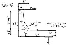
Collision forces shall be applied to the barrier or railing in the design of the cantilever slab. A force of 10 kips is to be applied at the top of the standard barrier or railing. This force is distributed through the barrier or railing to the slab. | |||
==== 751.40.8.1.4 Centrifugal Force ==== | |||
Structures on curves shall be designed for a horizontal radial force equal to the following percentage of the live load in all the lanes, without impact. | |||
{ | <math>\, C = \frac {6.68 S^2}{R}</math> | ||
| | Where: | ||
| | {| | ||
|<math>\, C</math>||= the centrifugal force in percent of the live load | |||
|- | |- | ||
| | |<math>\, S</math>||= the design speed in miles per hour | ||
|- | |||
|<math>\, R</math>||= the radius of the curve in feet | |||
|} | |} | ||
This force shall be applied at 6 feet above the centerline of the roadway with one design truck being placed in each lane in a position to create the maximum effect. Lane loads shall not be used in calculating centrifugal forces. | |||
The effects of superelevation shall be taken into account. | |||
==== 751.40.8.1.5 Lateral Earth Pressure ==== | |||
Structures which retain fills shall be designed for active earth pressures as | |||
<math>\, P_a = 0.5 (\gamma K_a) H^2</math> | |||
Where: | |||
{| | |||
|<math>\, P_a</math>||colspan="2"|= active earth pressure per length (lb/ft) | |||
< | |- | ||
|<math>\, \gamma</math>||colspan="2"|= unit weight of the back fill soil = 120 lb/ft³ | |||
< | |||
| | |||
|- | |- | ||
| | |<math>\, K_a</math>||colspan="2"|= coefficient of active earth pressure as given by Rankine’s formula | ||
|- | |- | ||
| | |<math>\, \gamma K_a</math>||= <math>\, p_a</math>||= equivalent fluid pressure (lb/ft³)(*) | ||
|- | |- | ||
| | |<math>\, H</math>||colspan="2"|= height of the back fill soil (ft) | ||
| | |||
| | |||
|( | |||
|} | |} | ||
'''Rankine's Formula''' | |||
The coefficient of active earth pressure <math>\, K_a</math> is: | |||
<math>\, K_a = (cos \alpha) \Bigg( \frac {cos \alpha - \sqrt{cos^2 \alpha - cos^2 \phi}}{cos \alpha + \sqrt{cos^2 \alpha - cos^2 \phi}} \Bigg)</math> | |||
Where: | |||
{| | |||
|<math>\, \phi</math>||= angle of internal friction of the backfill soil (*) | |||
|- | |||
|<math>\, \alpha</math>|| = the angle of incline of the backfill | |||
|} | |||
: | If the backfill surface is level, angle a is zero and <math>\, K_a</math> is: | ||
= | <math>\, K_a = \frac {1 - sin \phi}{1 + sin \phi}</math> | ||
(*) Use the internal friction angle indicated on the Bridge Memorandum. However, if the friction angle is not determined, use the minimum equivalent fluid pressure value, <math>\, p_a</math> , of 45 lb/ft³ for bridges and retaining walls. For box culverts use a maximum of 60 lb/ft³ and a minimum of 30 lb/ft³ for fluid pressure. | |||
'''Live Load Surcharge''' | |||
An additional earth pressure shall be applied to all structures which have live loads within a distance of half the structure height. This additional force shall be equal to adding 2'-0" of fill to that presently being retained by the structure. | |||
==== 751.40.8.1.6 Longitudinal Forces (Braking Forces) ==== | |||
A longitudinal force of 5% of the live load shall be applied to the structure. This load shall be 5% of the lane load plus the concentrated load for moment applied to all lanes and adjusted by the lane reduction factor. Apply this force at 6 feet above the top of slab and to be transmitted to the substructure through the superstructure. | |||
==== 751.40.8.1.7 Wind Load ==== | |||
Wind loads shall be applied to the structure regardless of length. | |||
The pressure generated by wind load is: | |||
<math>\, P = K V^2</math> | |||
< | Where: | ||
{| | |||
|<math>\, P</math>||= wind pressure in pounds per square foot | |||
|- | |||
| | |<math>\, V</math>||= design wind velocity = 100 miles per hour | ||
|- | |- | ||
| | |<math>\, K</math>||= 0.004 for wind load | ||
|} | |} | ||
Basic wind load (pressure) = 0.004 x (100)² = 40 lb/ft² | |||
'''Wind Load for Superstructure Design''' | |||
'''Transverse''' | |||
A wind load of the following intensity shall be applied horizontally at right angles to the longitudinal axis of the structure. | |||
*Trusses and Arches = 75 pounds per square foot = <math>\, W_t</math> | |||
*Girders and Beams = 50 pounds per square foot (*) = <math>\, W_t</math> (for plate girder lateral bracing check only) | |||
*The total force shall not be less than 300 pounds per linear foot in the plane of windward chord and 150 pounds per linear foot in the plane of the leeward chord on truss spans, and not less than 300 pounds per linear foot on girder spans. | |||
'''Wind Load for Substructure Design''' | |||
Forces transmitted to the substructure by the superstructure and forces applied directly to the substructure by wind load shall be as follows: | |||
'''Forces from Superstructure: Wind on Superstructure''' | |||
''' | '''Transverse''' | ||
A wind load of the following intensity shall be applied horizontally at right angles to the longitudinal axis of the structure. | |||
*Trusses and Arches = 75 pounds per square foot = <math>\, W_t</math> | |||
*Girders and Beams = 50 pounds per square foot (*) = <math>\, W_t</math> | |||
''(*) Use Wt = 60 lbs/ft² for design wind force on girders and beams If the column height on a structure is greater than 50 feet, where the height is the average column length from ground line to bottom of beam.'' | |||
The transverse wind force for a bent will be: | |||
<math>\, P = L \times H \times W_t</math> | |||
|valign="top"| | Where: | ||
{| | |||
|valign="top"|<math>\, L</math>||= length in feet = the average of two adjacent spans for intermediate bents and half of the length of the end span for end bents. | |||
|- | |- | ||
|valign="top"| | |valign="top"|<math>\, H</math>||= the total height of the girders, slab, barrier or raling and any superelevation of the roadway, in feet | ||
|- | |- | ||
|valign="top"| | |valign="top"|<math>\, W_t</math>|| = wind force per unit area in pounds per square foot | ||
|} | |} | ||
This transverse wind force will be applied at the top of the beam cap for the design of the substructure. | |||
'''Longitudinal (**)''' | |||
The standard wind force in the longitudinal direction shall be applied as a percentage of the transverse loading. Use approximately 25%. | |||
| | :{| | ||
|Truss and Arch Structures||<math>\, W_I</math>||= 75 x 0.25 = approximately 20 lbs/ft² | |||
|- | |- | ||
| | |Girder Structures||<math>\, W_I</math>||= 50 x 0.25 = approximately 12 lbs/ft² | ||
| | |||
| | |||
|} | |} | ||
The total longitudinal wind force <math>\, P</math> will be: | |||
<math>\, P = L \times H \times W_I</math> | |||
Where: | |||
{| | |||
|<math>\, L</math>||= the overall bridge length in feet | |||
|- | |||
|valign="top"|<math>\, H</math>||= the total height of the girders, slab, barrier or railing and anysuperelevation of the roadway, in feet | |||
|- | |||
|<math>\, W_I</math>||= wind force per unit area in pounds per square foot | |||
|} | |||
This longitudinal force is distributed to the bents based on their stiffness. (**) | |||
The longitudinal wind force for the bent will be applied at the top of the beam cap for the design of the substructure. | |||
'''Forces from Superstructure: Wind on Live Load''' | |||
A force of 100 pounds per linear foot of the structure shall be applied transversely to the structure along with a force of 40 pounds per linear foot longitudinally. These forces are assumed to act 6 feet above the top of slab. | |||
The transverse force is applied at the bents based on the length of the adjacent spans affecting them. The longitudinal force is distributed to the bents based on their stiffness. (**) | |||
(**) See [[751.2 Loads#751.2.4.6 Longitudinal Wind Force Distribution|EPG 751.2.4.6 Longitudinal Wind Force Distribution]]. | |||
'''Forces Applied Directly to the Substructure''' | |||
The transverse and longitudinal forces to be applied directly to the substructure elements shall be calculated from an assumed basic wind force of 40 lbs/ft². This wind force per unit area shall be multiplied by the exposed area of each substructure member in elevation (use front view for longitudinal force and side view for transversely force, respectively). These forces are acting at the center of gravity of the exposed portion of the member. | |||
A shape factor of 0.7 shall be used in applying wind forces to round substructure members. | |||
When unusual conditions of terrain or the special nature of a structure indicates, a procedure other than the Standard Specification may be used subject to approval of the Structural Project Manager. | |||
==== 751.40.8.1.8 Temperature Forces ==== | |||
Temperature stresses or movement need to be checked on all structures regardless of length. Generation of longitudinal temperature forces is based on stiffness of the substructure. (*) | |||
'''Coefficients''' | |||
{| | :{| | ||
|Steel:||Thermal - 0.0000065 ft/ft/°F | |||
| | |- | ||
|Concrete:||Thermal - 0.0000060 ft/ft/°F | |||
|- | |||
| ||Shrinkage - 0.0002 ft/ft (***) | |||
|- | |- | ||
| | | ||Friction - 0.65 for concrete on concrete | ||
|} | |} | ||
{|border="1" style="text-align:center;" cellpadding="5" align="center" | |||
|+'''Temperature Range From 60° F (**)''' | |||
|width="100pt"| ||width="50pt"|Rise||width="50pt"|Fall||width="50pt"|Range | |||
|- | |||
|Steel Structures||60°F||80°F||140°F | |||
|- | |||
|Concrete Structures||30°F||40°F||70°F | |||
|} | |||
(*) See [[751.2 Loads#751.2.4.7 Longitudinal Temperature Force Distribution|EPG 751.2.4.7 Longitudinal Temperature Force Distribution]]. | |||
(**) Temperature Range for expansion bearing design and expansion devices design see [[751.11 Bearings|EPG 751.11 Bearings]] and [[751.13 Expansion Devices|EPG 751.13 Expansion Devices]], respectively. | |||
(***) When calculating substructure forces of concrete slab bridges, the forces caused by the shrinkage of the superstructure should be included with forces due to temperature drop. This force can be ignored for most other types of bridges. | |||
==== 751.40.8.1.9 Sidewalk Loading ==== | |||
Sidewalk floors and their immediate support members shall be designed for a '''live load''' of 85 pounds per square foot of sidewalk area. Girders, trusses, and other members shall be design for the following sidewalk live load: | |||
:{| | |||
|width="150pt"|Spans 0 to 25 feet||width="100pt"|85 lbs/ft² | |||
|- | |||
|Spans 26 to 100 feet||60 lbs/ft² | |||
|- | |||
|Spans over 100 feet||use the following formula | |||
|} | |||
<math>\, P = \Bigg( 30 + \frac {3000}{L} \Bigg) \Bigg( \frac {55-W}{50} \Bigg)</math> | |||
Where: | |||
{| | |||
|<math>\, P</math>||= live load per square foot, max. 60 lbs/ft² | |||
|- | |||
|<math>\, L</math>||= loaded length of sidewalk in feet | |||
|- | |||
|<math>\, W</math>||= width of sidewalk in feet | |||
|} | |||
When sidewalk live loads are applied along with live load and impact, if the structure is to be designed by service loads, the allowable stress in the outside beam or stringer may be increased by 25 percent as long as the member is at least as strong as if it were not designed for the additional sidewalk load using the initial allowable stress. When the combination of sidewalk live load and traffic live load plus impact governs the design under the load factor method, use a b factor of 1.25 instead of 1.67. | |||
Unless a more exact analysis can be performed, distribution of sidewalk live loads to the supporting stringers shall be considered as applied 75 percent to the exterior stringer and 25 percent to the next stringer. | |||
==== 751.40.8.1.10 Other Loads ==== | |||
'''Stream Pressure''' | |||
Stream flow pressure shall be considered only in extreme cases. The affect of flowing water on piers shall not be considered except in cases of extreme high water and when the load applied to substructure elements is greater than that which is applied by wind on substructure forces at low water elevations. | |||
The pressure generated by stream flow is: | |||
<math>\, P = KV^2</math> | |||
< | Where: | ||
{| | |||
|<math>\, P</math>||= stream pressure in pounds per square foot | |||
|- | |||
|<math>\, V</math>||= design velocity of water in feet per second | |||
| | |- | ||
| | |<math>\, K</math>||= shape constant for the surface the water is in contact with. | ||
|- | |||
|<math>\, K</math>||= 1.4 for square-ended piers | |||
|- | |||
|<math>\, K</math>||= 0.7 for circular piers | |||
|- | |- | ||
| | |<math>\, K</math>||= 0.5 for angle-ended piers where the angle is 30 degrees or less | ||
|} | |} | ||
'''Ice Forces''' | |||
Ice forces on piers shall be applied if they are indicated on the Bridge Memorandum. | |||
'''Buoyancy''' | |||
Buoyancy shall be considered when its effects are appreciable. | |||
'''Fatigue in Structural Steel''' | |||
Steel structures subjected to continuous reversal of loads are to be designed for fatigue loading. | |||
'''Prestressing''' | |||
See [[751.22 P/S Concrete I Girders|EPG 751.22 P/S Concrete I Girders]]. | |||
'''Other Loads''' | |||
Other loads may need to be applied if they are indicated on the Bridge Memorandum. Otherwise see Structural Project Manager before applying any additional loads. | |||
==== 751.40.8.1.11 Group Loads ==== | |||
'''Group Loading (Service Load Design)''' | |||
Group loading combinations are: | |||
< | :{| | ||
|GP I SL||width="350pt"| <math>\, = D+L+I</math> ||100% | |||
|- | |||
|GP II SL||width="350pt"| <math>\, = D+W</math> ||125% | |||
|- | |||
|GP III SL||width="350pt"| <math>\, = D+L+I+0.3W+WL+LF</math> ||125% | |||
|- | |||
|GP IV SL||width="350pt"| <math>\, = D+L+I+T</math> ||125% | |||
|- | |||
|GP V SL||width="350pt"| <math>\, = D+W+T</math> ||140% | |||
|- | |||
|GP VI SL||width="350pt"| <math>\, = D+L+I+0.3W+WL+LF+T</math> ||140% | |||
|} | |||
Where: | |||
{| | |||
|<math>\, D</math>||= dead load | |||
|- | |||
|<math>\, L</math>||= live load | |||
|- | |||
|<math>\, I</math>||= live load impact | |||
|- | |||
|<math>\, W</math>||= wind load on structure | |||
|- | |||
|<math>\, WL</math>||= wind load on live load | |||
|- | |||
|<math>\, T</math>||= temperature force | |||
|- | |||
|<math>\, LF</math>||= longitudinal force from live load | |||
|} | |||
''' | '''Group Loading (Load Factor Design)''' | ||
Group loading combinations are: | |||
< | :{| | ||
|GP I LF||<math>\, = 1.3[\beta_d D+1.67 (L+I)]</math> | |||
|- | |||
|GP II LF||<math>\, = 1.3[\beta_d D+W]</math> | |||
|- | |||
|GP III LF||<math>\, = 1.3[\beta_d D+L+I+0.3W+WL+LF]</math> | |||
|- | |||
|GP IV LF||<math>\, = 1.3[\beta_d D+L+I+T]</math> | |||
|- | |||
|GP V LF||<math>\, = 1.25[\beta_d D+W+T]</math> | |||
|- | |||
|GP VI LF||<math>\, = 1.25[\beta_d D+L+I +0.3W+WL+LF+T]</math> | |||
|} | |||
Where: | |||
< | {| | ||
|<math>\, D</math>||= dead load | |||
|- | |||
|<math>\, L</math>||= live load | |||
< | |- | ||
|<math>\, I</math>||= live load impact | |||
|- | |||
|<math>\, W</math>||= wind load on structure | |||
|- | |||
|<math>\, WL</math>||= wind load on live load | |||
|- | |||
|<math>\, T</math>||= temperature force | |||
|- | |||
|<math>\, LF</math>||= longitudinal force from live load | |||
|- | |||
|<math>\, \beta_d</math>||= coefficient, see AASHTO Table 3.22.1A | |||
|} | |||
Other group loadings in AASHTO Table 3.22.1A shall be used when they apply. | |||
=== 751.40.8.2 Distribution of Loads === | |||
==== 751.40.8.2.1 Distribution of Dead Load ==== | |||
'''Composite Steel or Prestressed Concrete Structures''' | |||
The dead load applied to the girders through the slab shall be: | |||
'''Dead Load 1''' | |||
Non-composite dead loads should be distributed to girders (stringers) on the basis of continuous spans over simple supports. | |||
'''Dead Load 2''' | |||
Composite loads shall be distributed equally to all girders. The following are all Dead Load 2 loads: | |||
:Barrier or railing | |||
:Future wearing surface on slab | |||
:Sidewalks | |||
:Fences | |||
:Protective coatings and waterproofing on slab | |||
'''Concrete Slab Bridges''' | |||
Distribute entire dead load across full width of slab. | |||
For longitudinal design, heavier portions of the slab may be considered as concentrated load for entry into the "Continuous Structure Analysis" computer program. | |||
For transverse bent design, consider the dead load reaction at the bent to be a uniform load across entire length of the transverse beam. | |||
==== 751.40.8.2.2 Distribution of Live Load ==== | |||
Live loading to be distributed shall be the appropriate loading shown on the Bridge Memorandum. | |||
Applying Live Load to Structure | |||
'''Superstructure''' | |||
For application of live load to superstructure, the lane width is considered 12 feet. Each design vehicle has wheel lines which are 6 feet apart and adjacent design vehicles must be separated by 4 feet. | |||
'''Substructure''' | |||
To produce the maximum stresses in the main carrying members of substructure elements, multiple lanes are to be loaded simultaneously. The lane width is 12 feet. Partial lanes are not to be considered. Due to the improbability of coincident maximum loading, a reduction factor is applied to the number of lanes. This reduction however, is not applied in determining the distribution of loads to the stringers. | |||
{|border="1" style="text-align:center;" cellpadding="5" align="center" | |||
|+'''Distribution of Live Load to Beams and Girders''' | |||
!width="150pt"|Number of Lanes||width="150pt"|Percent | |||
|- | |||
|one or two lanes||100 | |||
|- | |||
|three lanes||90 | |||
|- | |||
|four lanes or more||75 | |||
|} | |||
'''Moment Distribution''' | |||
Moments due to live loads shall not be distributed longitudinally. Lateral distribution shall be determined from AASHTO Table 3.23.1 for interior stringers. Outside stringers distribute live load assuming the flooring to act as a simple span, except in the case of a span with a concrete floor supported by four or more stringers, then AASHTO 3.23.2.3.1.5 shall be applied. In no case shall an exterior stringer have less carrying capacity than an interior stringer. | |||
'''Shear Distribution''' | |||
As with live load moment, the reactions to the live load are not to be distributed longitudinally. Lateral distribution of live load shall be that produced by assuming the flooring to act as simply supported. Wheel lines shall be spaced on accordance with AASHTO 3.7.6 and shall be placed in a fashion which provides the most contribution to the girder under investigation, regardless of lane configuration. The shear distribution factor at bents shall be used to design bearings and bearing stiffeners. | |||
'''Deflection Distribution''' | |||
Deflection due to live loads shall not be distributed longitudinally. Lateral distribution shall be determined by averaging the moment distribution factor and the number of wheel lines divided by the number of girder lines for all girders. The number of wheel lines shall be based on 12 foot lanes. The reduction in load intensity (AASHTO Article 3.12.1) shall not be applied. | |||
Deflection Distribution Factor = <math>\, \cfrac {\big\{ \frac{2n}{N} \big\} + MDF}{2}</math> | |||
< | Where: | ||
{| | |||
|<math>\, n</math>||= number of whole 12 foot lanes on the roadway | |||
|- | |||
|<math>\, N</math>||= number of girder lines; | |||
|- | |||
|<math>\, MDF</math>||= Moment Distribution Factor. | |||
|} | |||
Example: 38'-0" Roadway (Interior Girder), <math>\, n=3</math>, <math>\, N=5</math>, <math>\, MDF=1.576</math> | |||
== | Deflection Distribution Factor = <math>\, \cfrac {\big\{ \frac{2 \times 3lanes}{5 girders} \big\} + 1.576}{2} = 1.388</math> | ||
=== | {|border="1" style="text-align:center;" cellpadding="5" align="center" | ||
|+'''Live Load Distribution Factors for Standard Roadway Widths''' | |||
!rowspan="2" width="75pt" |Roadway<br/>Width||rowspan="2" width="75pt"|Number<br/>Girders||rowspan="2" width="75pt"|Girder<br/>Spacing||colspan="3"|Exterior Girder||colspan="3"|Interior Girder||rowspan="2"|(1) | |||
|- | |||
!Mom.||Shear||Defl.||Mom.||Shear||Defl. | |||
|- | |||
|26’-0”||4||7’-6”||1.277||1.133||1.139||1.364||1.667||1.182||1.071 | |||
|- | |||
|28’-0”||4||8’-2”||1.352||1.204||1.176||1.485||1.776||1.243||1.167 | |||
|- | |||
|30’-0”||4||8’-8”||1.405||1.308||1.453||1.576||1.846||1.538||1.238 | |||
|- | |||
|32’-0”||4||9’-2”||1.457||1.400||1.479||1.667||1.909||1.584||1.310 | |||
|- | |||
|36’-0”||5||8’-2”||1.352||1.184||1.276||1.485||1.776||1.343||1.167 | |||
|- | |||
|38’-0”||5||8’-8”||1.405||1.231||1.303||1.576||1.846||1.388||1.238 | |||
|- | |||
|40’-0”||5||9’-0”||1.440||1.333||1.520||1.636||1.889||1.618||1.286 | |||
|- | |||
|44’-0”||5||9’-9”||1.515||1.487||1.558||1.773||1.974||1.687||1.393 | |||
|} | |||
<center> '''(1)''' Use when checking interior girder moment cyclical loading Case I Fatigue for one lane loading.</center> | |||
'''Distribution of Live Load to Substructure''' | |||
For substructure design the live load wheel lines shall be positioned on the slab to produce maximum moments and shears in the substructure. The wheel lines shall be distributed to the stringers on the basis of simple spans between stringers. The number of wheel lines used for substructure design shall be based on 12 foot lanes and shall not exceed the number of lanes times two with the appropriate percentage reduction for multiple lanes where applicable. | |||
In computing these stresses generated by the lane loading, each 12 foot lane shall be considered a unit. Fractional units shall not be considered. | |||
'''Distribution of Loads to Slabs''' | |||
For simple spans, the span length shall be the distance center to center of supports but need not be greater than the clear distance plus the thickness of the slab. Slabs for girder and floor beam structures should be designed as supported on four sides. | |||
For continuous spans on steel stringers or on thin flanged prestressed beams (top flange width to thickness ratios > 4.0), the span length shall be the distance between edges of top flanges plus one quarter of each top flange width. When the top flange width to thickness is < 4.0 the span distance shall be the clear span between edges of the top flanges. | |||
When designing the slab for live load, the wheel line shall be placed 1 foot from the face of the barrier or railing if it produces a greater moment. | |||
'''Bending Moments in Slab on Girders''' | |||
The load distributed to the stringers shall be: | |||
<math>\, \Bigg( \frac {S + 2}{32} \Bigg) </math> P20 or P25 = Moment in foot-pounds per-foot width of slab. | |||
Where: | |||
{| | |||
|<math>\, S</math>||= effective span length between girders in feet | |||
|- | |||
|P20 or P25||= wheel line load for HS20 or HS20 Modified design Truck in kips. | |||
|} | |||
For slabs continuous over 3 or more supports, a continuity factor of 0.8 shall be applied. | |||
''' | '''Main Reinforcement Parallel to Traffic''' | ||
This distribution may be applied to special structure types when its use is indicated. | |||
'''Distribution of Live Load to Concrete Slab Bridges''' | |||
Live load for transverse beam, column and pile cap design shall be applied as concentrated loads of one wheel line. The number of wheel lines used shall not exceed the number of lanes x 2 with the appropriate reduction where applicable. | |||
For slab longitudinal reinforcement design, use live load moment distribution factor of 1/E for a one-foot strip slab with the appropriate percentage reduction. | |||
< | <math>\, E = 4' + 0.06S, E (max.) = 7'</math> | ||
< | Where: | ||
{| | |||
|<math>\, E</math>||= Width of slab in feet over which a wheel is distributed | |||
|- | |||
|<math>\, S</math>||= Effective span length in feet. | |||
|} | |||
For slab deflection, use the following deflection factor for a one-foot strip slab without applying percentage reduction. | |||
( | Deflection Factor = (Total number of wheel line) / (width of the slab) | ||
==== 751.40.8.2.3 Frictional Resistance ==== | |||
The frictional resistance varies with different surfaces making contact. In the design of bearings, this resistance will alter how the longitudinal forces are distributed. The following table lists commonly encountered materials and their coefficients. These coefficients may be used to calculate the frictional resistance at each bent. | |||
{|border="1" style="text-align:center;" cellpadding="5" align="center" | |||
|- | |||
!colspan="4"|Frictional Resistance of Expansion Bearings | |||
|- | |||
!colspan="2"|Bearing Type||Coef.||General Data | |||
|- | |||
!colspan="2"|Type C Bearing | |||
|0.14 | |||
|rowspan=10| Coef. of sliding friction<br/>steel to steel = 0.14 | |||
Coef. for pin and rocker<br/>type bearing = | |||
<math>\, \frac {0.14 (Radius\ of\ pin)}{Radius\ of\ Rocker}</math> | |||
Frictional Force = <br/>Reaction x Coef. | |||
|- | |||
!colspan="2"|6” Diameter Roller | |||
|0.01 | |||
|- | |||
!colspan="2"|Type D Bearing|| | |||
|- | |||
!Pin Diameter||Rocker Radius|| | |||
|- | |||
|2”||6.5”||0.0216 | |||
|- | |||
|2”||7”||0.0200 | |||
|- | |||
|2”||7.5”||0.0187 | |||
|- | |||
|2”||8”||0.0175 | |||
|- | |||
|2”||10.5”||0.0133 | |||
|- | |||
!colspan="2"|PTFE Bearing | |||
|0.0600 | |||
|} | |||
The design of a bent with one of the above expansion bearings will be based on the maximum amount of load the bearing can resist by static friction. When this static friction is overcome, the longitudinal forces are redistributed to the other bents. | |||
The maximum static frictional force at a bent is equal to the sum of the forces in each of the bearings. The vertical reaction used to calculate this maximum static frictional force shall be Dead Loads only for all loading cases. Since the maximum longitudinal load that can be experienced by any of the above bearings is the maximum static frictional force, the effects of longitudinal wind and temperature can not be cumulative if their sum is greater than this maximum static frictional force. | |||
Two conditions for the bents of the bridge are to be evaluated. | |||
#Consider the expansion bents to be fixed and the longitudinal loads distributed to all of the bents. | |||
#When the longitudinal loads at the expansion bearings are greater than the static frictional force, then the longitudinal force of the expansion bearings is equal to the dynamic frictional force. It is conservative to assume the dynamic frictional force to be zero causing all longitudinal loads to be distributed to the remaining bents. | |||
=== 751.40.8.3 Unit Stresses === | |||
==== 751.40.8.3.1 Fatigue in Structural Steel ==== | |||
Steel structures subjected to continuous reversal of loads are to be designed for fatigue loading. | |||
AADTT, annual average daily truck traffic (one direction), shall be indicated on the Bridge Memorandum. Based on AADTT, the fatigue case and corresponding stress cycles can be obtained from ''AASHTO Table 10.3.2A''. | |||
When Case I fatigue is considered, it is necessary to check fatigue due to truck loading for both the 2,000,000 and over 2,000,000 stress cycles. For the over 2,000,000 stress cycles, the moment distribution factor for all stringers or girders (for fatigue stresses only) will be based on '''one''' lane loaded. For truck loading 2,000,000 cycles and lane loading 500,000 cycles, use the moment distribution factor based on two or more traffic lanes (same as for design moment). | |||
The number of cycles to be used in the fatigue design is dependent on the case number and type of load producing maximum stress as indicated in AASHTO Table 10.3.2A. | |||
The allowable fatigue stress range based on the fatigue stress cycles can be obtained from ''AASHTO Table 10.3.1A''. | |||
The type of live load used to determine the number of cycles will be the type of loading used to determine the maximum stress at the point under consideration. | |||
In continuous beams, the maximum stresses may be produced by the truck loading at some points, but by lane loading at other points. However, if the lane loading governs, then the longitudinal members should also be checked for truck loading. | |||
Only live loading and impact stresses need to be considered when designing for fatigue. | |||
Fatigue criteria applies only when the stress range is one of tension to tension or reversal. The fatigue criteria does not apply to the stress range from compression to compression. | |||
All fracture critical structures, those which consist of only one or two main carrying members, trusses or single box girders, shall be considered as Non-redundant structures. Use the appropriate table which accompanies these structures. | |||
==== 751.40.8. | ==== 751.40.8.3.2 Reinforced Concrete ==== | ||
'''Allowable Stresses of Reinforcing Steel''' | |||
<math>\, | Tensile stress in reinforcement at service loads, <math>\, f_s</math>: | ||
{| | {| | ||
| | !colspan="2" align="left"|Concrete | ||
|- | |- | ||
|<math>\, | |width="250pt"|Reinforcing Steel (Grade 40)||<math>\, f_s</math>||= 20,000 psi | ||
|- | |- | ||
|<math>\, | |width="250pt"|Reinforcing Steel (Grade 60)||<math>\, f_s</math>||= 24,000 psi | ||
|} | |} | ||
For compression stress in beams, see ''AASHTO Article 8.15.3.5''. | |||
For compression stress in columns, see ''AASHTO Article 8.15.4''. | |||
For fatigue stress limit, see ''AASHTO Article 8.16.8.3''. | |||
'''Fatigue in Reinforcing Steel''' | |||
<math>\, | For flexural members designed with reference to load factors and strengths by Strength Design Method, stresses at service load shall be limited to satisfy the requirements for fatigue. Reinforcement should be checked for fatigue at all locations of peak service load stress ranges and at bar cut-off locations except for concrete deck slab in multi-girder applications. | ||
'''Allowable Stress Range:''' <math>\, fr_{allow}</math> | |||
The allowable stress range is found using the equation listed below and the minimum stresses from dead load, live load, and impact based on service loads. | |||
The term minimum stress level fmin for this formula indicates the algebraic minimum stress level: tension stress with a positive sign and compression stress with a negative sign. | |||
<math>\, fr_{allow} = 21 - 0.33 f_{min} + 8(r/h)</math> | |||
Where: | Where: | ||
{| | {| | ||
|<math>\, | |<math>\, fr_{allow}</math>||= allowable stress range (ksi) | ||
|- | |- | ||
|<math>\, | |<math>\, f_{min}</math>||= algebraic minimum stress level ksi): | ||
|- | |- | ||
| | | ||positive if tension, negative if compression. | ||
|- | |- | ||
|<math>\, | |valign="top"|<math>\, r/h</math>||= ratio of base radius to height of rolled-on transverse deformation; if the actual value is not know, 0.3 may be used. | ||
|- | |- | ||
|<math> | |<math>fr_{allow}</math>||= <math>\, 23.4 - 0.33 f_{min}</math> when <math>\, r/h | ||
= 0.3</math> | |||
|} | |} | ||
Fatigue research has shown that increasing minimum tensile stress results in a decrease in fatigue strength for a tension to tension stresses case. The fatigue strength increases with a bigger compressive stress in a tension to compression stresses case. | |||
'''Actual Stress Range:''' <math>\, fr_{act}</math> | |||
<math>\, | The actual stress range, <math>\, fr_{act}</math>, is found using dead load, live load, and impact from service loads. | ||
{| | {| | ||
|<math>\, \ | |<math>\, fr_{act}</math>||colspan="2"|= <math>\, f_{GT} - f_{LT}</math> | ||
|- | |||
|<math>\, f_{GT}</math>||colspan="2"|= greatest tension stress level (ksi), always positive. | |||
|- | |||
| ||colspan="2"|(Not necessary to check compression to compression for fatigue.) | |||
|- | |||
|<math>\, f_{LT}</math>||colspan="2"|= algebraic least stress level (ksi): | |||
|- | |||
| ||<math>\, f_{LT}</math>||= positive if the least stress is tension | |||
|- | |||
| || ||'''(tension to tension stresses)''' | |||
|- | |||
| ||<math>\, f_LT</math>||= negative if the least stress is compression | |||
|- | |- | ||
| | | || ||(tension to compression stresses) | ||
|} | |} | ||
'''Tension and Compression Stress Computation''' | |||
Tension and compression stress are determined by using the following formulae for double reinforced concrete rectangular beams. | |||
<math>\, f_s</math> = tensile stress in reinforcement at service loads (ksi) | |||
:Tensile stress <math>\, f_s = \frac {M}{A_s j d}</math> | |||
<math>\, f'_s</math> = compressive stress in reinforcement at service loads (ksi) | |||
= | :Compressive stress <math>\, f'_s = \frac {M}{A_s j d} \Bigg( \cfrac {k - \frac {d^1}{d}} {1 - k} \Bigg)</math> | ||
Where: | |||
= | <math>\, j = \cfrac {k^2 \Big( 1 - \frac {k}{c} \Big) + 2 \rho'n \Big( k - \frac {d'}{d} \Big) \Big( 1 - \frac {d'}{d} \Big)}{k^2 + 2 \rho'n \Big( k - \frac {d'}{d} \Big)}</math> '''Eq. 2.2-1''' | ||
<math>\, k = \sqrt{2n \Bigg( \rho + \rho' \Bigg( \frac{d'}{d}\Bigg) \Bigg) + n^2 \big( \rho + \rho' \big)^2 - n \big( \rho + \rho' \big)}</math> '''Eq. 2.2-2''' | |||
{| | {| | ||
|<math>\, | |<math>\, \rho</math>||= tension reinforcement ratio, <math>\, \rho = \frac{A_s}{bd}</math> | ||
|- | |||
|<math>\, \rho'</math>||= compression reinforcement ratio, <math>\, \rho' = \frac{A'_s}{bd}</math> | |||
|- | |||
|<math>\, A_s</math>||= area of tension reinforcement (sq. inch) | |||
|- | |||
|<math>\, A'_s</math>||= area of compression reinforcement (sq. inch) | |||
|- | |||
|<math>\, b</math>||= width of beam (inch) | |||
|- | |||
|<math>\, d</math>||= distance from extreme compression fiber to centroid of tension reinforcement (inch) | |||
|- | |||
|<math>\, d'</math>||= distance from extreme compression fiber to centroid of compression reinforcement (inch) | |||
|- | |||
|<math>\, jd</math>||= distance from tensile steel to resultant compression (inch) | |||
|- | |- | ||
|<math>\, | |<math>\, kd</math>||= distance from neutral plane to compression surface (inch) | ||
|- | |- | ||
|<math>\, | |<math>\, n</math>||= ratio of modulus of elasticity of steel to that of concrete | ||
|} | |} | ||
=== 751.40.8.4 Standard Details === | |||
==== 751.40.8.4.1 Welding Details ==== | |||
All welding shall be detailed in accordance with ANSI / AASHTO / AWS D1.5, Bridge Welding Code. | |||
For ASTM A709, Grade 36 steel (Service Load Design <math>\, F_u</math> = 58,000 psi) the allowable shear stress in fillet welds (<math>\, F_V</math>) is: | |||
<math>\, F_V = 0.27 F_u</math> | |||
Where: | |||
{| | |||
|<math>\, F_V</math>||= allowable basic shear stress | |||
|- | |||
|<math>\, F_u</math>||= tensile strength of the electrode classification but not greater than the tensile strength of the connected part | |||
|} | |||
{|border="1" style="text-align:center;" cellpadding="5" align="center" | |||
''' | |+'''Allowable Shear Loads for Fillet Welds (*)''' | ||
|'''Size of Fillet Weld'''<br/>(Inch)||'''Allowable Shear Loads per Length'''<br/>(Pound per lineal inch) | |||
''' | |- | ||
|1/8”||1,380 | |||
|- | |||
|3/16”||2,075 | |||
|- | |||
|1/4"||2,770 | |||
|- | |||
|5/16”||3,460 | |||
|- | |||
|3/8”||4,150 | |||
|- | |||
|1/2"||5,535 | |||
|- | |||
|5/8”||6,920 | |||
|- | |||
|3/4"||8,300 | |||
|- | |||
|7/8”||9,690 | |||
|- | |||
|1”||11,070 | |||
|} | |||
(*) Allowable Shear Load = <math>\, (0.27)(58000 psi)(0.707xSize of Weld)(L)</math> | |||
<math>\, | |||
Where: | Where: | ||
{| | {| | ||
| | |align="right"| <math>\, L</math>||= Effective Length, in inch | ||
|- | |- | ||
| | |align="right"| <math>\, (0.707xSize of Weld)</math>||= Effective Throat, in inch | ||
|- | |- | ||
| | |align="right"| <math>\, (0.707xSize of Weld)(L)</math>||= Effective weld area in sq. inch | ||
|} | |} | ||
==== 751.40.8.4.2 Development and splicing of Reinforcement ==== | |||
===== 751.40.8.4.2.1 General ===== | |||
''' | '''Development of Tension Reinforcement''' | ||
Development lengths for tension reinforcement shall be calculated in accordance with AASHTO Article 8.25. Development length modification factors described in AASHTO Articles 8.25.3.2 and 8.25.3.3 shall only be used in situations where development length without these factors is difficult to attain. All other modification factors shown shall be used. | |||
Development lengths for tension reinforcement have been tabulated on the following pages and include the modification factors except those described above. | |||
'''Lap Splices of Tension Reinforcement''' | |||
Lap splices of reinforcement in tension shall be calculated in accordance with AASHTO Article 8.32.1 and 8.32.3. Class C splices are preferred when possible, however it is permissible to use Class A or B when physical space is limited. The designer shall satisfy AASHTO Table 8.32.3.2 when using Class A or B splices. It should be noted that As required is based on the stress encountered at the splice location, which is not necessarily the maximum stress used to design the reinforcement. | |||
Temperature and shrinkage reinforcement is assumed to fully develop the specified yield stresses. Therefore the development length shall not be reduced by (<math>\, A_s</math> required)/(<math>\, A_s</math> supplied). | |||
Splice lengths for tension reinforcement have been tabulated on the following pages and include the development length modifications as described above. | |||
''' | '''Development of Tension Hooks''' | ||
Development of tension hooks shall be calculated in accordance with AASHTO Article 8.29. Hook length modification factors described in Articles 8.29.3.3 and 8.29.3.4 shall only be used in situations where hook length without these factors is difficult to attain. All other modification factors shown shall be used. | |||
Development lengths of tension hooks have been tabulated on the following pages and include the modification factors except those described above. | |||
''' | '''Development of Compression Reinforcement''' | ||
Development lengths for compression reinforcement shall be calculated in accordance with AASHTO Article 8.26. Development length modification factors described in AASHTO Articles 8.26.2.1 and 8.26.2.2 shall only be used in situations where development length without these factors is difficult to attain. All other modification factors shown shall be used. | |||
Development lengths for compression reinforcement have been tabulated on the following pages and include the modification factors except those described above. | |||
'''Lap Splices of Compression Reinforcement''' | |||
Lap splices of reinforcement in compression shall be calculated in accordance with AASHTO Article 8.32.1 and 8.32.4. | |||
Splice lengths for compression reinforcement have been tabulated on the following pages. | |||
'''Mechanical Bar Splices''' | |||
Mechanical bar splices may be used in situations where it is not possible or feasible to use lap splices. Mechanical bar splices shall meet the criteria of AASHTO Article 8.32.2. Refer to the manufacturers literature for more information on the design of mechanical bar splices. | |||
===== 751.40.8.4.2.2 Development and Tension Lap Splice Lengths - Top Bars (<math>\, F_y</math> = 60 ksi) ===== | |||
<center>[[Image:751.40 reinforcement- Development and Tension Lap Splice Lengths - Top Bars (Fy = 60 ksi).gif]]</center> | |||
Top reinforcement is placed so that more than 12” of concrete is cast below the reinforcement. | |||
Class A splice =1.0 <math>\, L_d</math>, Class B splice =1.3 <math>\, L_d</math>, Class C splice =1.7 <math>\, L_d</math> | |||
Use development and tension lap splices of <math>\, f'_c</math> = 4 ksi for concrete strengths greater than 4 ksi. | |||
<math>\, | ===== 751.40.8.4.2.3 Development and Tension Lap Splice Lengths - Other Than Top Bars (<math>\, F_y</math> = 60 ksi) ===== | ||
<center>[[Image:751.40 reinforcement- Development and Tension Lap Splice Lengths - Other Than Top Bars (Fy = 60 ksi).gif]]</center> | |||
=== | Class A splice =1.0 <math>\, L_d</math>, Class B splice =1.3 <math>\, L_d</math>, Class C splice =1.7 <math>\, L_d</math> | ||
' | Use development and tension lap splices of <math>\, f'_c</math> = 4 ksi for concrete strengths greater than 4 ksi. | ||
===== 751.40.8.4.2.4 Development and Lap Splice Lengths - Bars in Compression (<math>\, F_y</math> = 60 ksi) ===== | |||
< | <center>[[Image:751.40 reinforcement- Development and Lap Splice Lengths - Bars in Compression (Fy = 60 ksi).gif]]</center> | ||
Development length for spirals, <math>\, L_d</math>, <math>\, _{spiral}</math>, should be used if reinforcement is enclosed in a spiral of not less than 1/4” diameter and no more than 4” pitch. See AASHTO 8.26 for special conditions. | |||
All values are for splices with the same size bars. For different size bars, see AASHTO 8.32.4. | |||
(*) Lap splices for #14 and #18 bars are not permitted except as column to footing dowels. | |||
===== 751.40.8.4.2.5 Development of Standard Hooks in Tension, Ldh (<math>\, F_y</math> = 60 ksi) ===== | |||
The development length, <math>\, L_{dh}</math>, is measured from the critical section to the outside edge of hook. The tabulated values are valid for both epoxy and uncoated hooks. | |||
<center>[[Image:751.40 reinforcement- Development of Standard Hooks in Tension, Ldh (Fy = 60 ksi).gif]]</center> | |||
'''Case A''' - For #11 bar and smaller, side cover (normal to plane of hook) less than 2 1/2 inches and for a 90 degree hook with cover on the hook extension less than 2 inches. | |||
''' | '''Case B''' - For #11 bar and smaller, side cover (normal to plane of hook) greater than 2 1/2 inches and for a 90-dgree hook with cover on the hook extension 2 inches or greater. | ||
See | (*) See Structural Project Manager before using #14 or #18 hook. | ||
{| border="0" cellpadding="3" cellspacing="1" align="center" style="text-aling:center" | |||
| rowspan="4"|[[Image:751.40 reinforcement-DETAIL NEAR FREE EDGE OR CONSTRUCTION JOINT.gif]] | |||
| rowspan="4" width="40px"| | |||
|[[Image:751.40 reinforcement- HOOKED-BAR DETAILS FOR DEVELOPMENT OF STANDARD HOOKS.gif]] | |||
|- | |||
|(1) = <math>\,4d_b</math> (#3 thru #8) | |||
|- | |||
|(1) = <math>\,5d_b</math> (#9, #10 and #11) | |||
|- | |||
|(1) = <math>\,6d_b</math> (#14 and #18) | |||
|- | |||
!DETAILS NEAR FREE EDGE<br/>OR CONSTRUCTION JOINT|| ||HOOKED-BAR DETAILS FOR<br/>DEVELOPMENT OF STANDARD HOOKS | |||
|} | |||
===== 751.40.8.4.2.6 Development of Uncoated Grade 40 Deformed Bars in Tension, <math>\, L_d</math> (AASHTO 8.25) ===== | |||
''' | {|border="1" style="text-align:center;" cellpadding="5" align="center" cellspacing="0" | ||
|+'''Bars spaced laterally less than 6 inches on center or less than 3 inches concrete cover in direction of the spacing''' | |||
!rowspan="2" width="50pt"|Bar||colspan="2"| <math>\, f'_c</math> = 3 ksi||colspan="2"|<math>\, f'_c</math> = 4 ksi||colspan="2"|<math>\, f'_c</math> = 5 ksi | |||
|- | |||
|width="75pt"|<math>\, L_d</math>||width="75pt"|<math>\, L_d</math> Top bar||width="75pt"|<math>\, L_d</math>||width="75pt"|<math>\, L_d</math> Top bar||width="75pt"|<math>\, L_d</math>||width="75pt"|<math>\, L_d</math> Top bar | |||
| | |||
|- | |- | ||
| | |#3||12||12||12||12||12||12 | ||
|- | |- | ||
| | |#4||12||12||12||12||12||12 | ||
|- | |- | ||
| | |#5||12||14||12||14||12||14 | ||
|- | |- | ||
| | |#6||13||19||12||17||12||17 | ||
|- | |- | ||
| | |#7||18||25||16||22||14||20 | ||
| | |||
| | |||
|- | |- | ||
| | |#8||23||33||20||28||18||25 | ||
|- | |- | ||
| | |#9||30||41||26||36||23||32 | ||
|- | |- | ||
| | |#10||38||52||33||45||29||41 | ||
|- | |- | ||
| | |#11||46||64||40||56||36||50 | ||
|- | |- | ||
| | |#14||63||87||54||76||49||68 | ||
|- | |- | ||
| | |#18||81||113||70||98||63||88 | ||
|} | |} | ||
{|border="1" style="text-align:center;" cellpadding="5" align="center" cellspacing="0" | |||
''' | |+'''Bars spaced laterally 6 inches or more on center and at least 3 inches concrete cover in direction of the spacing''' | ||
!rowspan="2" width="50pt"|Bar||colspan="2"| <math>\, f'_c</math> = 3 ksi||colspan="2"|<math>\, f'_c</math> = 4 ksi||colspan="2"|<math>\, f'_c</math> = 5 ksi | |||
| | |||
|- | |- | ||
| | |width="75pt"|<math>\, L_d</math>||width="75pt"|<math>\, L_d</math> Top bar||width="75pt"|<math>\, L_d</math>||width="75pt"|<math>\, L_d</math> Top bar||width="75pt"|<math>\, L_d</math>||width="75pt"|<math>\, L_d</math> Top bar | ||
|- | |||
|#3||12||12||12||12||12||12 | |||
|- | |||
|#4||12||12||12||12||12||12 | |||
|- | |||
|#5||12||12||12||12||12||12 | |||
|- | |||
|#6||12||15||12||14||12||14 | |||
|- | |||
|#7||15||20||13||18||12||16 | |||
|- | |||
|#8||19||26||16||23||15||20 | |||
|- | |||
|#9||24||33||21||29||19||26 | |||
|- | |- | ||
| | |#10||30||42||26||36||23||33 | ||
|- | |- | ||
| | |#11||37||52||32||45||29||40 | ||
|- | |- | ||
| | |#14||50||70||44||61||39||54 | ||
|- | |- | ||
| | |#18||65||90||56||78||50||70 | ||
|} | |} | ||
===== 751.40.8.4.2.7 Minimum lap length for uncoated Grade 40 tension lap splices, <math>\, L_{lap}</math> (AASHTO 8.32) ===== | |||
|<math>\, | {|border="1" style="text-align:center;" cellpadding="5" align="center" cellspacing="0" | ||
|+'''Bars spaced less than 6 inches laterally on center and at least 3 inches concrete cover in direction of the spacing''' | |||
!rowspan="2"| ||colspan="9"|Other than Top Bars||colspan="9"|Top Bars | |||
|- | |||
|colspan="3"|<math>\, f'_c</math> = 3 ksi||colspan="3"|<math>\, f'_c</math> = 4 ksi||colspan="3"|<math>\, f'_c</math> = 5 ksi||colspan="3"|<math>\, f'_c</math> = 3 ksi||colspan="3"|<math>\, f'_c</math> = 4 ksi||colspan="3"|<math>\, f'_c</math> = 5 ksi | |||
|- | |||
|Bar||A||B||C||A||B||C||A||B||C||A||B||C||A||B||C||A||B||C | |||
|- | |||
|#3||12||12||12||12||12||12||12||12||12||12||16||21||12||16||21||12||16||21 | |||
|- | |||
|#4||12||12||14||12||12||14||12||12||14||12||16||21||12||16||21||12||16||21 | |||
|- | |- | ||
| | |#5||12||13||17||12||13||17||12||13||17||14||19||24||14||19||24||14||19||24 | ||
|- | |- | ||
| | |#6||13||17||22||12||16||21||12||16||21||19||24||31||17||22||29||17||22||29 | ||
|- | |- | ||
| | |#7||18||23||30||16||20||26||14||19||24||25||32||42||22||28||37||20||26||34 | ||
|- | |- | ||
| | |#8||23||30||40||20||26||34||18||24||31||33||42||55||28||37||48||25||33||43 | ||
|- | |- | ||
| | |#9||30||38||50||26||33||43||23||30||39||41||54||70||36||47||61||32||42||54 | ||
|- | |- | ||
| | |#10||38||49||63||33||42||55||29||38||49||52||68||89||45||59||77||41||53||69 | ||
|- | |- | ||
| | |#11||46||60||78||40||52||68||36||46||61||64||84||109||56||72||95||50||65||85 | ||
|} | |} | ||
{|border="1" style="text-align:center;" cellpadding="5" align="center" cellspacing="0" | |||
|+'''Bars spaced 6 inches or more laterally on center and at least 3 inches concrete cover in direction of the spacing''' | |||
!rowspan="2"| ||colspan="9"|Other than Top Bars||colspan="9"|Top Bars | |||
|- | |||
|colspan="3"|<math>\, f'_c</math> = 3 ksi||colspan="3"|<math>\, f'_c</math> = 4 ksi||colspan="3"|<math>\, f'_c</math> = 5 ksi||colspan="3"|<math>\, f'_c</math> = 3 ksi||colspan="3"|<math>\, f'_c</math> = 4 ksi||colspan="3"|<math>\, f'_c</math> = 5 ksi | |||
|- | |||
|Bar||A||B||C||A||B||C||A||B||C||A||B||C||A||B||C||A||B||C | |||
|- | |||
|#3||12||12||12||12||12||12||12||12||12||12||16||21||12||16||21||12||16||21 | |||
|- | |||
|#4||12||12||12||12||12||12||12||12||12||12||16||21||12||16||21||12||16||21 | |||
|- | |||
|#5||12||12||14||12||12||14||12||12||14||12||16||21||12||16||21||12||16||21 | |||
|- | |||
|#6||12||14||18||12||13||17||12||13||17||15||19||25||14||18||23||14||18||23 | |||
|- | |||
|#7||15||19||24||13||16||21||12||15||20||20||26||34||18||23||29||16||21||27 | |||
|- | |||
|#8||19||24||32||16||21||28||15||19||25||26||34||44||23||29||38||20||26||34 | |||
|- | |||
|#9||24||31||40||21||27||35||19||24||31||33||43||56||29||37||49||26||33||44 | |||
|- | |||
|#10||30||39||51||26||34||44||23||30||39||42||54||71||36||47||62||33||42||55 | |||
|- | |||
|#11||37||48||63||32||42||54||29||37||49||52||67||87||45||58||76||40||52||68 | |||
|} | |||
==== 751.40.8. | ==== 751.40.8.4.3 Miscellaneous ==== | ||
''' | '''Negative Moment Steel over Intermediate Supports''' | ||
Dimension negative moment steel over intermediate supports as shown. | |||
<center>[[Image:751.40 reinforcement-Negative Moment Steel over Intermediate Supports.gif]]</center> | |||
{| | |||
!colspan="2" align="left"|Prestressed Structures: | |||
|- | |||
|(1)||Bar length by design. | |||
|- | |||
|(2)||Reinforcement placed between longitudinal temperature reinforcing in top. | |||
|} | |||
:{| | |||
|Bar size:||#5 bars at 7-1/2" cts. (Min.) | |||
|- | |||
| ||#8 bars at 5" cts. (Max.) | |||
|} | |||
{| | |||
!colspan="2" align="left"|Steel Structures: | |||
|- | |||
|valign="top"|(1)||Extend into positive moment region beyond "Anchor" Stud shear connectors at least '''40 x bar diameter x 1.5''' (Epoxy Coated Factor)(*) as shown below. (AASHTO 10.38.4.4 & AASHTO 8.25.2.3) | |||
|- | |||
|(2)||Use #6 bars at 5" cts. between longitudinal temperature reinforcing in top. | |||
|} | |||
<center>[[Image:751.40 reinforcement-elevation of girder showning negative moment steel.gif]]</center> | |||
{| | |||
|(*)||40 x bar diameter x 1.5 = 40 x 0.75" x 1.5 = 45” for #6 epoxy coated bar. | |||
|} | |||
=== 751.40.8.5 General Superstructure === | |||
==== 751.40.8.5.1 Concrete Slabs ==== | |||
===== 751.40.8.5.1.1 Design Criteria ===== | |||
'''Slabs on Girders''' | |||
'''Stresses:''' | |||
:{| | |||
|<math>\, f_c</math>||= 1,600 psi | |||
|- | |||
|<math>\, f'_c</math>||= 4,000 psi | |||
|- | |||
|<math>\, n</math>||= 8 | |||
|- | |||
|<math>\, f_y</math>||= 60,000 psi | |||
|} | |||
''' | '''Moments Over Interior Support''' (Use for positive moment reinf. also) (Sec. 1.5 E40A) | ||
{| | |||
|Dead Load =|| <math>\, -0.107wS^2</math> ||(Continuous over 5 supports) | |||
|- | |||
|Dead Load =|| <math>\, -0.100wS^2</math> ||(Continuous over 4 supports) | |||
|} | |||
{| | |||
|Live Load =|| <math>\, (S + 2) \frac {P}{32}</math> ||width="20pt"| ||Continuity Factor||= 0.8 | |||
|- | |||
{| | | || || ||align="right"|Impact Factor||= 1.3 | ||
| | |- | ||
| || || ||align="right"|P||= 16 Kips for HS20 | |||
|- | |- | ||
| | | || || ||align="right"|P||= 20 Kips for HS20 Modified | ||
|- | |- | ||
| | |colspan="5"| | ||
|- | |- | ||
| | |Design Load:||colspan="4"| <math>\, M_u = 1.3 (M_{DL} + 1.67 M_{LL+I})</math> | ||
|} | |} | ||
<div id="Cantilever Moment"></div> | |||
'''Moment | '''Cantilever Moment''' | ||
Dead Load = Moment due to slab, F.W.S. and S.B.C. | |||
Live Load: | |||
Wheel Load = <math>\, M_{LL=I} = \frac {Px}{E}</math> | |||
Where: | |||
{| | |||
|<math>\, P</math>||= Wheel load (apply impact factor) | |||
|- | |||
|<math>\, x</math>||= Distance from load to support (ft.) | |||
|- | |||
|<math>\, E</math>||= <math>\, 0.8x + 3.75</math> | |||
|} | |||
Collision Load = <math>M_{COLL} = \frac {Py}{E}</math> | |||
Where: | Where: | ||
{| | {| | ||
|<math>\, | |<math>\, P</math>||= 10 kips (Collision force) | ||
|- | |- | ||
|<math>\, | |<math>\, y</math>||= Moment arm (Curb ht.+ 1/2 Slab th.) | ||
|- | |- | ||
|<math>\, | |<math>\, E</math>||= <math>\, 0.8x + 5.0</math> | ||
|} | |} | ||
Where: | |||
{| | |||
|<math>\, x</math>||= Distance from center of gravity of barrier to support | |||
|} | |||
{|border="0" cellpadding="5" cellspacing="1" align="center" style="text-align:center" | |||
{|border=" | |||
|- | |- | ||
|width="250pt" align="left"|The "support" is assumed at the 1/4 point of the minimum flange. | |||
|rowspan="4"|[[Image:751.40.8.5.1.1 slab cantilever.jpg|275px]] | |||
|- | |- | ||
| | |width="250pt" align="left"|Wheel loads and collision loads shall not be applied simultaneously. | ||
|- | |- | ||
| | |width="250pt" align="left"|Use the greater of the two for the Design Load. | ||
|- | |- | ||
| | |width="250pt" align="left"|Design Load:<br./><math>\, M_u = 1.3 (M_{DL} + 1.67 M_{LL+I})</math> | ||
|- | |- | ||
| | ! ||Slab Cantilever Section | ||
|} | |} | ||
Design of top reinforcement is based on maximum moment over supports or cantilever moment. Flexural reinforcement shall meet the criteria of AASHTO Art. 8.16.3. | |||
When designing for bottom transverse reinforcement, a 1" wearing surface is removed from the effective depth. | |||
Prestressed panels replace the bottom transverse reinforcement. | |||
Prestressed panels are assumed to carry DL1 stresses. Therefore, the negative moment due to DL1 at interior supports may be neglected. | |||
The maximum P/S panel width (clear span + 6") for HS20 Modified is 9'-6". (Based on 10'-0" girder spacing and 10" flanges) The maximum P/S panel width (clear span + 6") for HS20 is 9'-11". | |||
'''Distribution of Flexural Reinforcement''' | |||
Allowable Stress: <math>\, f_s = \frac {Z}{(d_c \times A)^{1/3}} \le 0.6 f_y</math> | |||
Where: | |||
{| | |||
|<math>\, Z</math>||= 130 k/in. | |||
|- | |||
|valign="top"|<math>\, d_c</math>||= Dist. from extreme tension fiber to center of closest bar (concrete cover shalll not be taken greater than 2") | |||
|- | |||
|<math>\, A</math>||= Effective tension area of concrete | |||
|- | |||
| ||= <math>\, 2d_c s</math> | |||
|- | |||
|<math>\, s</math>||= Bar spacing ctr. to ctr. | |||
|} | |||
Actual Stress: <math>\, f_s = \frac {M_W}{A_S \times j \times d}</math> | |||
<math>\, | |||
Where: | Where: | ||
{| | {| | ||
|<math>\, | |<math>\, M_W</math>||= Service load moment | ||
|- | |||
|<math>\, A_S</math>||= Area of steel | |||
|- | |||
|<math>\, j</math>||= <math>\, 1 - k/3</math> | |||
|- | |||
|<math>\, k</math>||= <math>\, \sqrt {2n\rho + (n \rho)^2 - n \rho}</math> | |||
|- | |||
|<math>\, n</math>||= <math>\, E_S/E_C</math> | |||
|- | |||
|<math>\, \rho</math>||= <math>\, A_S /(b \times d)</math> | |||
|- | |||
|<math>\, b</math>||= Effective width | |||
|- | |- | ||
| | |<math>\, d</math>||= Effective depth | ||
|} | |} | ||
Distribution of flexural reinforcement does not need to be checked in | |||
concrete considered unexposed to weather. | |||
'''Longitudinal distribution reinforcement:''' | |||
Top of slab - use #5 bars at 15" cts. for temperature distribution. | |||
Bottom of slab - by design. | |||
'''Negative moment reinforcement over supports:''' | |||
Steel structures - add. #6 bars at 5" between #5 bars. | |||
P/S girder structures - by design. | |||
Additional reinforcement over supports shall be a minimum of #5 bars and a maximum of #8 bars at 5" ctrs. When necessary, replace the #5 temperature reinforcement with a larger bar to satisfy negative moment reinforcement requirement, but keep all bars within two bar sizes. | |||
Note: See details of negative moment reinforcement. | |||
{|border="0" cellpadding="5" cellspacing="1" align="center" style="text-align:center" | |||
|- | |||
|colspan="2"|[[Image:751.40 general superstructure-sections thru slab showing negative moment reinforcement.gif]] | |||
|- | |||
!width="50%"|CIP Slab||width="50%"|P\S Panel Slab | |||
|} | |||
{|border="0" cellpadding="5" cellspacing="1" align="center" style="text-align:center" | |||
|- | |||
|valign="top" align="right"|[[Image:751.40 circled 1.gif]]||align="left" width="400pt" |3" Cl. preferred min., 2 3/4" Cl. preferred min. for P/S panels to accommodate #8 bars over supports and 2 1/2" Cl. absolute min. by AASHTO 8.22.1. | |||
|} | |||
Method of measurement: | |||
The area of the concrete slab shall be measured and computed to the nearest square yard. This area shall be measured transversely from out to out of slab and longitudinally from end to end of bridge slab. | |||
'''Precast Prestressed Panels''' | |||
3" Precast prestressed concrete panels with 5-1/2" minimum cast-in-place concrete will be the standard slab used on all girder superstructures except curved steel structures. | |||
Concrete for prestressed panels shall be Class A1 with <math>\, f'{c}</math> = 6,000 psi, <math>\, f'_{ci}</math> = 3,500 psi. Prestressing tendons shall be uncoated, low-relaxation, seven-wire(7) strands for prestressed concrete conforming to AASHTO M203 Grade 270, with nominal diameter of strand = 3/8" and area = 0.085 sq.in., minimum ultimate strength = 22.95 kips (270 ksi), and strand spacing = 4.5 inches. | |||
Panels shall be set on joint filler or polystyrene bedding material. Filler thickness shall be a Min. of 3/4" and a Max. of 2". Standard filler width is 1 1/2" except at splice plates where 3/4" Min. is allowed to clear splice bolts. Joint filler thickness may be reduced to a minimum of 1/4" over splice plates on steel structures. For prestressed girder structures, joint filler thickness may be varied within these limits to offset girder camber or at the contractor's option a uniform 3/4" (Min.) thickness may be used throughout. The same thickness shall be used under any one edge of any panel and the maximum change in thickness between adjacent panels shall be 1/4 inch for steel spans and 1/2 inch for concrete spans. | |||
Standard roadway cross sections and slab reinforcement for HS20 and HS20 Modified live loads are shown in this section. Reinforcement shown is for a cast-in-place slab or a P/S panel slab with the bottom layer of reinforcement between girders being replaced by the panels. Cantilever reinforcement details for P/S panel slab are shown in this section. | |||
:Maximum panel width (clear span + 6") = 9'-6" for HS20 Modified. | |||
:Maximum panel width (clear span + 6") = 9'-11" for HS20. | |||
When a barrier or railing is permanently required on the structure, other than at the edge of slab, precast prestressed panels will not be allowed in the bay underneath the barrier or railing. Prestressed panels are not allowed for use as simply supported for live loads, i.e. staging, where only two supports may be provided for live loads. | |||
'''S.I.P.''' | |||
Stay-in-place corrugated metal forms with cast-in-place concrete may be used on horizontally curved steel structures with the approval of the Structural Project Manager. | |||
The standard slab reinforcements shown in this section for HS20 live load were designed using S.I.P. Dead Loads. If design is for HS20 Modified, the standard slab reinforcement needs to be checked for S.I.P. forms. | |||
|- | |||
The bottom transverse reinforcement shall maintain a 1" clear distance from the top of forms. | |||
| | |||
'''C.I.P.''' | |||
8 1/2" cast-in-place concrete slab with conventional forming may be used at the contractor's option, on all girder structures. Conventional forming shall also be used between girders with stage construction joints. | |||
{|border="0" cellpadding="5" cellspacing="1" align="center" style="text-align:center" | |||
|+'''Details of Precast Prestressed Panels Prestressed Structure:''' | |||
|colspan="1"|[[Image:751.40 general superstructure-panels - square ends - prestressed structures.gif]] | |||
|[[Image:751.40 general superstructure-panels - skewed ends - prestressed structures.gif]] | |||
|- | |||
!colspan="1"|Panels-Squared Ends | |||
!Panels-Skewed Ends | |||
|- | |||
!colspan="3"|PLAN OF PRECAST PRESTRESSED PANELS PLACEMENT | |||
|} | |||
{|border="0" cellpadding="5" cellspacing="0" align="center" style="text-align:center" | |||
|valign="top"|(1) | |||
|align="left"|End panels shall be dimensioned 1" min. to 1-1/2"<br/>max. from the inside face of diaphragm. | |||
|rowspan="3" colspan="2"|[[Image:751.40 general superstructure-panels - section thru const joint.gif]] | |||
|- | |||
|valign="top"|(2) | |||
|align="left"|S-Bars shown are bottom steel in slab between<br/>panels and used with squared end panels only. | |||
|- | |||
|valign="top"|(3) | |||
|align="left"|Extend S-Bars 18 inches beyond the front<br/>face of end bents only. | |||
|- | |- | ||
!colspan="2"| | |colspan="2" rowspan="2"|[[Image:751.40 general superstructure-panels - section a-a.gif]] | ||
!colspan="2"|Section Thru Const. Joint | |||
|- | |- | ||
|valign="top"|(*) | |||
|align="left" valign="top"|Adjust the permissible construction joint to a clearance of 6<br/>inches minimum from the joints of the panels. | |||
Note: All reinforcement other than prestressing strands shall<br/>be epoxy coated. | |||
|- | |- | ||
| | !colspan="2"|Section A-A | ||
|colspan="2" rowspan="5"|[[Image:751.40 general superstructure-panels - section thru cantilever.gif]] | |||
|- | |- | ||
| | |valign="top"|(**) | ||
|align="left" valign="top"|3/4" Min. thru 2" max. thickness and 1 1/2" width of<br/>preformed fiber expansion joint material or Sec 1057<br/>or polystyrene bedding material Sec 1073. | |||
|- | |- | ||
| | |colspan="2"| | ||
|- | |- | ||
| | |colspan="2"| | ||
|- | |- | ||
| | |colspan="2"| | ||
|- | |- | ||
|colspan="2"| | |||
| | !colspan="2"|Section Thru Cantilever | ||
|} | |} | ||
{|border="0" cellpadding="5" cellspacing="0" align="center" style="text-align:center" | |||
|+'''Details of Precast Prestressed Panels Steel Structure:''' | |||
|colspan="2"|[[Image:751.40 general superstructure-panels - square ends - end bent - steel structure.gif|250px]] | |||
|[[Image:751.40 general superstructure-panels - square ends - int end bent - steel structure.gif|250px]] | |||
|[[Image:751.40 general superstructure-panels - square ends - int bent - steel structure.gif|250px]] | |||
|- | |||
=== | !colspan="2"|End Bent | ||
!End Bent (Integral) | |||
!Int. Bent (Exp. Gap) | |||
|- | |||
!colspan="4"|Panels-Squared Ends | |||
!colspan=" | |||
|- | |- | ||
| | |colspan="2"|[[Image:751.40 general superstructure-panels - skewed ends - int bent exp gap - steel structure.gif]] | ||
|[[Image:751.40 general superstructure-panels - skewed ends - end bent - steel structure.gif]] | |||
|[[Image:751.40 general superstructure-panels - skewed ends - int end bent - steel structure.gif]] | |||
|- | |- | ||
!colspan="2"|Int. Bent (Exp. Gap) | |||
!End Bent | |||
!End Bent (Integral) | |||
|- | |- | ||
| | !colspan="4"|Panels-Skewed Ends | ||
|- | |- | ||
| | !colspan="4"|PLAN OF PRECAST PRESTRESSED PANELS PLACEMENT | ||
|- | |- | ||
|valign="top"| | |valign="top"|(1) | ||
|align="left"|End panels shall be dimensioned 1" min. to 1 1/2" max. from the inside face of diaphragm. | |||
|colspan="2" rowspan="2"|[[Image:751.40 general superstructure-panels - section a-a steel structure.gif]] | |||
|- | |- | ||
| | |valign="top"|(2) | ||
|align="left"|S-Bars shown are bottom steel in slab between panels and used with squared end panels only. | |||
| | |||
|- | |- | ||
| | |valign="top"|(3) | ||
|align="left"|Extend S-bars 18 inches beyond the front face of end bents only. | |||
|colspan="2"|'''Section A-A'''<br/>(*) Over splice plates, 3/4" Min. thickness allowed. | |||
|- | |- | ||
| | |valign="top"|(5) | ||
|align="left" valign="top"|S-Bars shown are used with skewed end panels, or square end panels of square structures only. The #5-S Bars will extend the width of slab (30" lap if necessary) or to within 3" of expansion device assemblies. | |||
|colspan="2" rowspan="3"|[[Image:751.40 general superstructure-panels - section b-b steel structure.gif]] | |||
|- | |- | ||
| | |valign="top"|Note: | ||
|align="left"|All reinforcement other than prestressing strands shall be epoxy coated. | |||
|- | |- | ||
| | | | | ||
| | |||
|- | |- | ||
| | | | ||
| | |||
|colspan="2"|'''Part Section B-B''' | |||
|- | |- | ||
| | |colspan="4"|[[Image:751.40 general superstructure-panels - section thru cantilever steel structure.gif]] | ||
|- | |- | ||
| | |colspan="4"|'''Section Thru Cantilever''' | ||
|} | |} | ||
{|border="0" cellpadding="5" cellspacing="1" align="center" style="text-align:center" | |||
|+'''Details of Precast Prestressed Panels for all Structures:''' | |||
|colspan="2"|[[Image:751.40 general superstructure-panels - plan of precast prestressed panel.gif]] | |||
|colspan="2"|[[Image:751.40 general superstructure-panels - plan of precast prestressed panel (skewed end-option).gif]] | |||
|- | |- | ||
| | !colspan="2" valign="top"|Plan of Precast Prestressed Panel | ||
!colspan="2" valign="top"|Plan of Precast Prestressed Panel<br/>(Skewed End-Optional) | |||
|- | |- | ||
| | |(*) | ||
|align="left"|= 3" (Typ.) for steel girder structures | |||
!colspan="2" rowspan="3"|[[Image:751.40 general superstructure-panels - detail a (precast panels).gif]] | |||
|- | |- | ||
| | |(*) | ||
|align="left"|= 3" (Typ.) for P/S girder structures | |||
|- | |- | ||
|<math>\, | |(**) | ||
|align="left"|Use #3-P3 bars if panel is skewed <math>\,45^\circ</math> or greater. | |||
|- | |- | ||
| | |colspan="2" rowspan="2"|[[Image:751.40 general superstructure-panels - section b-b (precast panels).gif]] | ||
!colspan="2"|Detail "A" | |||
|- | |- | ||
|< | |valign="top"|Note: | ||
|align="left" valign="top"|Area of Strand = Astra = 0.085 sq. in./strand<br/>Initial prestressing stress = fsi = (0.75)(270 ksi) = 202.5 ksi<br/>Initial prestressing force = Astra x fsi<br/>= (0.085 sq. in./strand)(202.5 ksi) = 17.2 kips/strand | |||
|- | |- | ||
!colspan="2"|Section B-B | |||
|- | |} | ||
| | |||
===== 751.40.8.5.1.2 Details of Concrete Slabs for Structures ===== | |||
=== | {|border="0" cellpadding="5" cellspacing="1" align="center" style="text-align:center" | ||
|- | |- | ||
| | |[[Image:751.40 general superstructure-HS20 (26ft0in ROADWAY - 4 GIRDER).gif]] | ||
|- | |- | ||
| | !colspan="2"|HS20 (26'-0" ROADWAY - 4 GIRDER) | ||
|- | |- | ||
| | |colspan="2"| | ||
|- | |- | ||
| | |[[Image:751.40 general superstructure-HS20 modified (26ft0in ROADWAY - 4 GIRDER).gif]] | ||
|- | |- | ||
| | !colspan="2"|HS20 Modified (26'-0" ROADWAY - 4 GIRDER) | ||
|- | |- | ||
| | |colspan="2"| | ||
|- | |- | ||
| | |[[Image:751.40 general superstructure-HS20 (28ft0in ROADWAY - 4 GIRDER).gif]] | ||
|- | |- | ||
| | !colspan="2"|HS20 (28'-0" ROADWAY - 4 GIRDER) | ||
|- | |- | ||
| | |colspan="2"| | ||
|- | |- | ||
| | |[[Image:751.40 general superstructure-HS20 modified (28ft0in ROADWAY - 4 GIRDER).gif]] | ||
|- | |- | ||
| | !colspan="2"|HS20 Modified (28'-0" ROADWAY - 4 GIRDER) | ||
|- | |- | ||
| | |colspan="2"| | ||
|- | |- | ||
| | |[[Image:751.40 general superstructure-HS20 (30ft0in ROADWAY - 4 GIRDER).gif]] | ||
| | |- | ||
!colspan="2"|HS20 (30'-0" ROADWAY - 4 GIRDER) | |||
= | |- | ||
|colspan="2"| | |||
|- | |||
|[[Image:751.40 general superstructure-HS20 modified (30ft0in ROADWAY - 4 GIRDER).gif]] | |||
' | |- | ||
!colspan="2"|HS20 Modified (30'-0" ROADWAY - 4 GIRDER) | |||
|- | |||
|colspan="2"| | |||
|- | |||
|[[Image:751.40 general superstructure-HS20 (32ft0in ROADWAY - 4 GIRDER).gif]] | |||
|- | |||
!colspan="2"|HS20 (32'-0" ROADWAY - 4 GIRDER) | |||
|- | |||
|colspan="2"| | |||
|- | |||
|[[Image:751.40 general superstructure-HS20 modified (32ft0in ROADWAY - 4 GIRDER).gif]] | |||
|- | |||
!colspan="2"|HS20 Modified (32'-0" ROADWAY - 4 GIRDER) | |||
|- | |||
|colspan="2"| | |||
|- | |||
|[[Image:751.40 general superstructure-HS20 (36ft0in ROADWAY - 5 GIRDER).gif]] | |||
|- | |||
!colspan="2"|HS20 (36'-0" ROADWAY - 5 GIRDER) | |||
|- | |||
|colspan="2"| | |||
|- | |||
|[[Image:751.40 general superstructure-HS20 modified (36ft0in ROADWAY - 5 GIRDER).gif]] | |||
|- | |||
!colspan="2"|HS20 Modified (36'-0" ROADWAY - 5 GIRDER) | |||
|- | |||
|colspan="2"| | |||
|- | |||
|[[Image:751.40 general superstructure-HS20 (38ft0in ROADWAY - 5 GIRDER)(unsymmetrical).gif]] | |||
|- | |||
!colspan="2"|HS20 (38'-0" ROADWAY - 5 GIRDER)(Unsymmetrical) | |||
|- | |||
|colspan="2"| | |||
|- | |||
|[[Image:751.40 general superstructure-HS20 modified (38ft0in ROADWAY - 5 GIRDER)(unsymmetrical).gif]] | |||
|- | |||
!colspan="2"|HS20 Modified (38'-0" ROADWAY - 5 GIRDER)(Unsymmetrical) | |||
|- | |||
|colspan="2"| | |||
|- | |||
|[[Image:751.40 general superstructure-HS20 (40ft0in ROADWAY - 5 GIRDER).gif]] | |||
|- | |||
!colspan="2"|HS20 (40'-0" ROADWAY - 5 GIRDER) | |||
|- | |||
|colspan="2"| | |||
|- | |||
|[[Image:751.40 general superstructure-HS20 modified (40ft0in ROADWAY - 5 GIRDER).gif]] | |||
|- | |||
!colspan="2"|HS20 Modified (40'-0" ROADWAY - 5 GIRDER) | |||
|- | |||
|colspan="2"| | |||
|- | |||
|[[Image:751.40 general superstructure-HS20 (44ft0in ROADWAY - 5 GIRDER).gif]] | |||
|- | |||
!colspan="2"|HS20 (36'-0" ROADWAY - 5 GIRDER) | |||
|- | |||
|colspan="2"| | |||
|- | |||
|[[Image:751.40 general superstructure-HS20 modified (44ft0in ROADWAY - 5 GIRDER).gif]] | |||
|- | |||
!colspan="2"|HS20 Modified (36'-0" ROADWAY - 5 GIRDER) | |||
|- | |||
|colspan="2"| | |||
|} | |||
==== 751.40.8.5.2 Timber Floor ==== | |||
{|border="1" style="text-align:center;" cellpadding="5" align="center" | |||
|- | |||
!colspan="3"|Maximum stringer spacing as determined by strength of timber floor | |||
|- | |||
!colspan="3"|Stress = 1,200 lbs. per square inch | |||
''' | |- | ||
!width="200pt"| ||width="200pt"|H-10||width="200pt"|H-15 | |||
|- | |||
|(*) 3" x 12" Plank||18" + 1/2 Flange Width||16" + 1/2 Flange Width | |||
|- | |||
|4" Laminated Floor||2'-11" + 1/2 Flange Width||2'-3" + 1/2 Flange Width | |||
|- | |||
|6" Laminated Floor||6'-0" + 1/2 Flange Width||4'-4" + 1/2 Flange Width | |||
|- | |||
!colspan="3"|Stress = 1,600 lbs. per square inch | |||
|- | |||
! ||H-10||H-15 | |||
|- | |||
|3" x 12" Plank||23" + 1/2 Flange Width||21" + 1/2 Flange Width | |||
|- | |||
|4" Laminated Floor||3'-9" + 1/2 Flange Width||2'-11 1/2" + 1/2 Flange Width | |||
|- | |||
|6" Laminated Floor||7'-10 3/4" + 1/2 Flange Width||5'-9" + 1/2 Flange Width | |||
|} | |||
<center>(*) 3" x 12" Plank without treads.</center> | |||
==== 751.40.8.5.3 Steel Grid Bridge Flooring ==== | |||
In general, the 5" depth (concrete filled to half depth) steel grid bridge flooring shall be specified. Bar spacing may vary as necessary to meet minimum section modulus requirements. Main member spacing shall not exceed 10" and cross bar spacing shall not exceed 4". At present, the manufacturers of the following types have provided data to show they are acceptable: | |||
:Greulich 5" Standard | |||
:Foster 5" Standard | |||
The section properties <math>\, (n = 8)</math> and maximum span for HS20 loading have been computed for these types and are as follows: | |||
{|border="1" style="text-align:center;" cellpadding="5" align="center" | |||
|- | |||
|rowspan="3" width="75pt"|Company | |||
|rowspan="3"|(For Design<br/>Purpose only)<br/>Weight (PSF)<br/>(Steel & Conc.) | |||
|rowspan="3"|Main bar<br/>Spacing | |||
|rowspan="3"|Cross bar<br/>Spacing | |||
|colspan="3"|Moment of Inertia<br/><math>\, (in^4/Ft.)</math> | |||
|- | |||
|colspan="2"|Mid Span | |||
||Over-Support | |||
|- | |||
|Conc.||Steel||Steel | |||
|- | |||
|Greulich||width="100pt"|48.0||width="50pt"|7 1/2"||width="50pt"|3 3/4"||width="50pt"|99.41||width="50pt"|12.43||width="50pt"|9.03 | |||
|- | |||
|Foster||48.0||8"||4"||128.1||16.01||12.25 | |||
|} | |||
{|border="1" style="text-align:center;" cellpadding="5" align="center" | |||
|- | |||
|rowspan="3" width="75pt"|Company | |||
|colspan="4"|Section Modulus <math>\, (in^2/ft.)</math> | |||
|colspan="4"|Maximum Span (*) | |||
|- | |||
|colspan="2"|Mid-Span | |||
|colspan="2"|Over-Support | |||
|colspan="2"|Simple Span | |||
|colspan="2"|Continuous Spans | |||
|- | |||
|width="50pt"|Conc.<br/>(Top) | |||
|width="50pt"|Steel<br/>(Bott.) | |||
|width="50pt"|Steel<br/>(Top) | |||
|width="50pt"|Steel<br/>(Bott.) | |||
|width="50pt"|ASTM<br/>A709<br/>Gr. 36 | |||
|width="50pt"|ASTM<br/>A709<br/>Gr. 50W | |||
|width="50pt"|ASTM<br/>A709<br/>Gr. 36 | |||
|width="50pt"|ASTM<br/>A709<br/>Gr. 50W | |||
|- | |||
|Greulich||59.5||3.53||3.90||3.14||4'-4"||5'-10"||5'-10"||7'-1" | |||
|- | |||
|Foster||72.5||4.68||5.25||4.30||5'-9"||7'-5"||7'-2"||9'-4" | |||
|} | |||
The cross-section DETAILS used in computing the section properties are shown on the sketches on the following sheets. Maximum span determination included an allowance for a 35#/sq.ft. future | |||
wearing surface and assumed a wheel load to be distributed, normal to the main bars, over a width of 4'-0". | |||
(Place the following note on the Bridge Plans with the Steel Grid Details. | |||
Note: The steel grid deck shall be electrically grounded. | |||
(*) For main beams of grid either parallel or perpendicular to traffic. | |||
<center>[[Image:751.40 | <center>[[Image:751.40 general superstructure-greulich 5in standard.gif]]</center> | ||
{|border="1" style="text-align:center;" cellpadding="5" align="center" | |||
|- | |||
| ||Composite Section||Steel Section Only (net) | |||
|- | |||
|y||1.671"||2.317" | |||
|} | |||
<center>'''Greulich 5" Standard'''</center> | |||
==== | {|border="0" style="text-align:center;" cellpadding="2" align="center" | ||
|- | |||
|Note:||Dimensions obtained form Greulich plans. | |||
|} | |||
<center>[[Image:751.40 | <center>[[Image:751.40 general superstructure-foster 5in standard.gif]]</center> | ||
{|border="1" style="text-align:center;" cellpadding="5" align="center" | |||
|- | |||
| ||Composite Section||Steel Section Only (net) | |||
|- | |||
|y||1.766"||2.338" | |||
|} | |||
<center>'''Foster 5" Standard'''</center> | |||
{|border="0" style="text-align:center;" cellpadding="2" align="center" | |||
|- | |||
|Note:||Dimensions obtained form Foster Catalog. | |||
|} | |||
==== 751.40.8.5.4 Longitudinal Diagrams ==== | |||
===== 751.40.8.5.4.1 Hinged Beam Connections ===== | |||
The diagrams of various joints in steel structures are intended to be guides primarily for the determination of horizontal longitudinal dimensions for the plan view on the first sheet of plans. | |||
These diagrams are not to be detailed on the design plans. However, the arrangement of the joints should be useful in detailing the longitudinal diagram for structural steel, particularly for bridges on grades and vertical curves. | |||
Longitudinal dimensions for the plan of structural steel and for the plan of slab shall be horizontal from centerline bearing to centerline bearing. | |||
For proper correlation of details when developing plans for widening or redecking bridges, match the method of dimensioning on the new plans with the method used on the originals. | |||
{|border="0" cellpadding="5" cellspacing="1" align="center" style="text-align:center" | |||
|+'''Hinged Beam Connections''' | |||
|[[Image:751.40 general superstructure-Geometrics for Hinged Beam Connections for Bridges on Sag Vertical Curves1.gif]] | |||
{| border="0" cellpadding=" | |||
| | |||
|[[Image:751.40 | |||
|- | |- | ||
!Geometrics for Hinged Beam Connections for Bridges on Sag Vertical Curves | |||
|- | |- | ||
| | | | ||
|- | |- | ||
| | |[[Image:751.40 general superstructure-Geometrics for Hinged Beam Connections for Bridges on Flat Grade.gif]] | ||
|- | |- | ||
! | !Geometrics for Hinged Beam Connections for Bridges on Flat Grade | ||
|- | |- | ||
| | | | ||
|- | |- | ||
| | |[[Image:751.40 general superstructure-Geometrics for Hinged Beam Connections for Bridges on Straight, Plus Grades.gif]] | ||
|- | |- | ||
!Geometrics for Hinged Beam Connections for Bridges on Straight, Plus Grades | |||
|- | |- | ||
| | | | ||
|- | |- | ||
| | |[[Image:751.40 general superstructure-Geometrics for Hinged Beam Connections for Bridges on Crown Vertical Curves.gif]] | ||
|- | |- | ||
!Geometrics for Hinged Beam Connections for Bridges on Crown Vertical Curves | |||
|- | |- | ||
| | | | ||
|- | |- | ||
| | |[[Image:751.40 general superstructure-Geometrics for Hinged Beam Connections for Bridges on Sag Vertical Curves2.gif]] | ||
|- | |- | ||
!Geometrics for Hinged Beam Connections for Bridges on Sag Vertical Curves | |||
|- | |- | ||
| | | | ||
|- | |||
|[[Image:751.40 general superstructure-Geometrics for Hinged Beam Connections for Bridges on Symmetrical Vertical Curves.gif]] | |||
|- | |||
!Geometrics for Hinged Beam Connections for Bridges on Symmetrical Vertical Curves | |||
|- | |||
| | |||
|- | |- | ||
| | |[[Image:751.40 general superstructure-Geometrics for Hinged Beam Connections for Bridges on Crown Vertical Curves1.gif]] | ||
|- | |- | ||
!Geometrics for Hinged Beam Connections for Bridges on Crown Vertical Curves | |||
|} | |} | ||
{|border=" | {|border="0" cellpadding="5" cellspacing="1" align="center" style="text-align:center" | ||
|+''' | |+'''Hanger Beam Connections''' | ||
|[[Image:751.40 general superstructure-Geometrics for Hanger Beam Connections for Bridges on Crown Vertical Curves.gif]] | |||
|- | |||
!Geometrics for Hanger Beam Connections for Bridges on Crown Vertical Curves | |||
|- | |- | ||
| | | | ||
|- | |- | ||
| | |[[Image:751.40 general superstructure-Geometrics for Hanger Beam Connections for Bridges on Sag Vertical Curves.gif]] | ||
|- | |- | ||
| | !Geometrics for Hanger Beam Connections for Bridges on Sag Vertical Curves | ||
|} | |||
{|border="0" cellpadding="5" cellspacing="1" align="center" style="text-align:center" | |||
|+'''Pin Plate Connections''' | |||
|[[Image:751.40 general superstructure-Geometrics for Pin Plate Connections for Bridges on Crown Vertical Curves.gif]] | |||
|- | |- | ||
!Geometrics for Pin Plate Connections for Bridges on Crown Vertical Curves | |||
|- | |- | ||
| | | | ||
|- | |- | ||
| | |[[Image:751.40 general superstructure-Geometrics for Pin Plate Connections for Bridges on Sag Vertical Curves.gif]] | ||
|- | |- | ||
| | !Geometrics for Pin Plate Connections for Bridges on Sag Vertical Curves | ||
|} | |||
===== 751.40.8.5.4.2 Longitudinal Sections ===== | |||
{|border="0" cellpadding="5" cellspacing="1" align="center" style="text-align:center" | |||
|+'''Expansion Device at End Bent''' | |||
|Colspan="2"|[[Image:751.40 general superstructure-longitudinal sections-expansion device at end bent(not on grade).gif]] | |||
|- | |- | ||
| | !Bearing Stiffener||Connection Plate | ||
|- | |- | ||
| | !colspan="2"|Structures Not on Grade (Typical) | ||
|- | |- | ||
| | |colspan="2"| | ||
|- | |- | ||
| | |colspan="2"|[[Image:751.40 general superstructure-longitudinal sections-expansion device at end bent(on grade).gif]] | ||
|- | |- | ||
| | !Colspan="2"|Structures on Grade (Typical) | ||
|} | |} | ||
{|border="0" cellpadding="5" cellspacing="1" align="center" | |||
{|border=" | |||
|- | |- | ||
| | |align="right" valign="top"|(*)||width="400pt"|Parallel to Girder. All other dimensions shown are normal to backwall. | ||
|- | |- | ||
| | |align="right" valign="top"|(**)||width="400pt"|See [[751.13 Expansion Devices|EPG 751.13 Expansion Devices]] for dimension of overhang from end of stringer or girder to face of plate, edge of concrete or face of vertical leg of angle. | ||
|} | |||
{|border="0" cellpadding="5" cellspacing="1" align="center" style="text-align:center" | |||
|+'''No Expansion Device at End Bent''' | |||
|Colspan="2"|[[Image:751.40 general superstructure-longitudinal sections-no expansion device at end bent(not on grade) 1.gif]] | |||
|- | |- | ||
| | !Bearing Stiffener||Connection Plate | ||
|- | |- | ||
| | !colspan="2"|Structures Not on Grade (Typical) | ||
|- | |- | ||
| | |colspan="2"| | ||
|- | |- | ||
| | |colspan="2"|[[Image:751.40 general superstructure-longitudinal sections-no expansion device at end bent(on grade) 1.gif]] | ||
|- | |- | ||
| | !Colspan="2"|Structures on Grade (Typical) | ||
|} | |||
{|border="0" cellpadding="5" cellspacing="1" align="center" | |||
|- | |- | ||
| | |align="right" valign="top"|(*)||width="400pt"|Parallel to Girder. All other dimensions shown are normal to backwall. | ||
|- | |- | ||
| | |align="right" valign="top"|(**)||width="400pt"|18" min. (Use same dimension as the expansion device end on 3-span continuous, if it is not more than 2" greater.) | ||
|- | |- | ||
| | |align="right" valign="top"|(***)||width="400pt"|3" min. for type C, D and E bearing, and 2" min. for an elastomeric bearing. | ||
|} | |} | ||
{|border=" | |||
|+''' | {|border="0" cellpadding="5" cellspacing="1" align="center" style="text-align:center" | ||
|+'''Intermediate Bent''' | |||
|width="300pt"|[[Image:751.40 general superstructure-longitudinal sections-intermediate bent-no expansion device.gif]] | |||
|width="300pt"|[[Image:751.40 general superstructure-longitudinal sections-intermediate bent-expansion device.gif]] | |||
|- | |- | ||
| | !No Expansion Device||Expansion Device | ||
|} | |||
{|border="0" cellpadding="5" cellspacing="1" align="center" | |||
|- | |- | ||
| | |align="right" valign="top"|[[Image:751.40 circled 1.gif]]||width="400pt"|1/2" minimum overhang from end of stringer to face of plate, edge of concrete or face of vertical leg of angle. | ||
|- | |- | ||
| | |align="right" valign="top"|[[Image:751.40 circled 2.gif]]||width="400pt"|Gap as required for a particular type of expansion device. | ||
|- | |- | ||
| | |align="right" valign="top"|[[Image:751.40 circled 3.gif]]||width="400pt"|Expansion device gap plus 1 1/2" minimum (taken parallel to centerline stringer). | ||
|- | |- | ||
| | |align="right" valign="top"|(*)||width="400pt"|Parallel to Girder. All other dimensions shown are normal to centerline Bent. | ||
|- | |- | ||
| | |colspan="2" align=left" valign-"top"|Blockout shown is for Elastomeric Expansion Joint Seal. Check<br/>Bridge Memorandum for type of device for a particular structure. | ||
|} | |} | ||
{|border="0" cellpadding="5" cellspacing="1" align="center" style="text-align:center" | |||
|+'''Expansion Device at Any Bent''' | |||
|[[Image:751.40 general superstructure-longitudinal sections-expansion device at any bent-end(no grade).gif]] | |||
|[[Image:751.40 general superstructure-longitudinal sections-expansion device at any bent-int(no grade).gif]] | |||
|- | |- | ||
|( | !colspan="2"|Structures Not on Grade (Typical) | ||
|- | |- | ||
| | |colspan="2"| | ||
| | |||
|- | |- | ||
| | |colspan="2"|[[Image:751.40 general superstructure-longitudinal sections-expansion device at any bent-end(on grade).gif]] | ||
|- | |- | ||
!colspan="2"|Structures On Grade (Typical) | |||
|} | |} | ||
{|border="0" cellpadding="5" cellspacing="1" align="center" style="text-align:center" | |||
|+'''Point on Rotation of Bearings''' | |||
|[[Image:751.40 general superstructure-longitudinal sections-point of rotation of bearings-type c bearing.gif]] | |||
|[[Image:751.40 general superstructure-longitudinal sections-point of rotation of bearings-type c bearing grade 4% and greater.gif]] | |||
''' | |||
: | |||
|- | |- | ||
|< | !valign="top" width="300pt"|Type "C" Bearing||width="300pt"|Type "C" Bearing<br/>(Grade 4% and Greater) | ||
|- | |||
|colspan="2"| | |||
|- | |- | ||
| | |[[Image:751.40 general superstructure-longitudinal sections-point of rotation of bearings-type d bearing.gif]] | ||
|[[Image:751.40 general superstructure-longitudinal sections-point of rotation of bearings-type e bearing.gif]] | |||
|- | |- | ||
!width="300pt"|Type "D" Bearing||width="300pt"|Type "E" Bearing | |||
| | |||
| | |||
|- | |- | ||
| | |colspan="2"| | ||
|- | |- | ||
| | |[[Image:751.40 general superstructure-longitudinal sections-point of rotation of bearings-flat plate bearing.gif]] | ||
|[[Image:751.40 general superstructure-longitudinal sections-point of rotation of bearings-prestressed structure bearing pad.gif]] | |||
|- | |- | ||
| | !width="300pt"|Flat Plate Bearing<br/>(For Grade 2% and Greater)||width="300pt"|Prestressed Structure<br/>Bearing Pad | ||
|- | |- | ||
| | |colspan="2"| | ||
|- | |- | ||
|colspan=" | |colspan="2"|[[Image:751.40 general superstructure-longitudinal sections-point of rotation of bearings-steel structure bearing pad.gif]] | ||
|- | |- | ||
!colspan="2"|Steel Structure<br/>Bearing Pad | |||
|} | |} | ||
{|border="0" cellpadding="5" cellspacing="1" align="center" style="text-align:center" | |||
|+'''Blocking Diagram''' | |||
|[[Image:751.40 general superstructure-longitudinal sections-blocking diagram.gif]] | |||
|- | |||
!Elevation of Longitudinal Steel Diagram | |||
|} | |||
{|border="0" cellpadding="5" cellspacing="1" align="center" | |||
|- | |||
|align="right" valign="top"|Note:||width="400pt"|The typical elevation shown above should be detailed on the plans for all steel structures that are on vertical curve grades. | |||
|- | |||
| | |align="right" valign="top"|(1)||width="400pt"|Longitudinal dimensions are horizontal from centerline Brg. to centerline Brg. | ||
|- | |- | ||
| | |align="right" valign="top"|(*)||width="400pt"|Horizontal dimensions. | ||
|- | |- | ||
| | !colspan="2"|BLOCKING DIAGRAM SHOULD NOT BE USED FOR CAMBERED GIRDERS. | ||
|} | |} | ||
==== 751.40.8.5.5 Miscellaneous Bearing Connections ==== | |||
===== 751.40.8.5.5.1 Typical Details of “Hinged Connection" ===== | |||
|< | {|border="0" cellpadding="5" cellspacing="1" align="center" style="text-align:center" | ||
|- | |||
|colspan="3"|[[Image:751.40 general superstructure-misc details-section showing hinged beam conn1.gif]] | |||
|- | |||
!colspan="3"|Section Showing Hinged Beam Connection | |||
|- | |||
|colspan="3"| | |||
|- | |||
|rowspan="2"|[[Image:751.40 general superstructure-misc details-detail of web at radius transition.gif]] | |||
|valign="bottom"|[[Image:751.40 general superstructure-misc details-plan of brg plate.gif]] | |||
|rowspan="2"|[[Image:751.40 general superstructure-misc details-typ welding details for stiffeners.gif]] | |||
|- | |||
!valign="top"|Plan of Brg. Plate | |||
|- | |||
!Detail of Web at<br/>Radius Transition|| ||Typical Welding Details<br/>for Stiff. Plates | |||
|- | |||
|colspan="3"| | |||
|- | |||
|[[Image:751.40 general superstructure-misc details-section c-c.gif]] | |||
| colspan="2" rowspan="2" | | |||
{|border="0" cellpadding="3" cellspacing="1" align="center" | |||
|- | |||
|valign="top" align="right"|"D"||align="left" width="375pt" |Gap as required for expansion (3" Min.) | |||
|- | |||
|valign="top" align="right"|"J"||align="left" width="375pt" |5" for bearing with 3" web thickness. Use 6" for all others. | |||
|- | |||
|valign="top" align="right"|[[Image:751.40 circled 1.gif]]||align="left" width="375pt" |Dimension to be 1/3 brg. length (Typ.) | |||
|- | |||
|valign="top" align="right"|(*)||align="left" width="375pt" |To be used unless greater depth is required by design. | |||
|- | |||
|valign="top" align="right"|(**)||align="left" width="375pt" |See [[751.13 Expansion Devices|EPG 751.13 Expansion Devices]] | |||
|- | |||
|valign="top" align="right"|Note:||align="left" width="375pt" |Web thickness and size of fillet weld connecting bearing stiffener plate to web as required by design. | |||
|- | |- | ||
| | |valign="top" align="right"| ||align="left" width="375pt" |Plans for bridges on a grade or vertical curve shall have the conn. detailed in relation to the slope of the girders and stringers. | ||
|} | |||
|- | |- | ||
!Section C-C | |||
|} | |} | ||
{|border="0" cellpadding="5" cellspacing="1" align="center" style="text-align:center" | {|border="0" cellpadding="5" cellspacing="1" align="center" style="text-align:center" | ||
|- | |- | ||
| | |colspan="4"|[[Image:751.40 general superstructure-misc details-section showing hinged beam conn2.gif]] | ||
|- | |- | ||
!colspan="4"|Section Showing Hinged Beam Connection | |||
|- | |||
|colspan="4"| | |||
|- | |- | ||
| | |colspan="4"|[[Image:751.40 general superstructure-misc details-sections d-d & e-e.gif]] | ||
|- | |- | ||
!width="15%"| ||Section D-D||Section E-E||width="18%"| | |||
|- | |- | ||
|colspan="4"| | |||
| | |- | ||
|colspan="4"|[[Image:751.40 general superstructure-misc details-typical welding details for stiffeners.gif]] | |||
|- | |||
!colspan="4"|Typical Welding Details<br/>for Stiff. Plates | |||
|} | |||
{|border="0" cellpadding="5" cellspacing="1" align="center" style="text-align:center" | |||
|- | |||
|valign="top" align="right"|(*)||align="left"|See below for dimension "G". | |||
|- | |||
|valign="top" align="right"|(**)||align="left"|See [[751.13 Expansion Devices|EPG 751.13 Expansion Devices]] | |||
| | |||
|- | |- | ||
|valign="top"| | |valign="top" align="right"|"F"||align="left"|= Gap as required for expansion (3" Min.). | ||
|- | |- | ||
| | |valign="top" align="right"|"H"||align="left"|= 10 3/4" Min. (12" preferred.) | ||
|- | |- | ||
| | |valign="top" align="right"|"J"||align="left"|= 5" for bearing with 3" web thickness. Use 6" for all others. | ||
|- | |- | ||
| | |colspan="2"|All dimensions shown are minimum, increase, as necessary. | ||
|} | |} | ||
{|border="1" style="text-align:center;" cellpadding="5" align="center" | |||
|+'''Allowable Dead Load Reactions for Various Depths of "G"''' | |||
!width="75pt"|Web<br/>Thickness | |||
!width="75pt"|Depth<br/>"G" | |||
|< | !width="150pt"|(*) Allowable<br/>Dead Load<br/>Reactions, Kips<br/>(At 150% Overstress) | ||
|rowspan="9"| | |||
!width="75pt"|Web<br/>Thickness | |||
!width="75pt"|Depth<br/>"G" | |||
!width="150pt"|(*) Allowable<br/>Dead Load<br/>Reactions, Kips<br/>(At 150% Overstress) | |||
|- | |- | ||
| | |5/16"||8"||45.0||7/16"||8"||63.0 | ||
|- | |- | ||
| | |5/16"||9"||50.6||7/16"||9"||70.8 | ||
|- | |- | ||
| | |5/16"||10"||56.2||7/16"||10"||78.7 | ||
|- | |- | ||
| | |5/16"||11"||61.8||7/16"||11"||86.6 | ||
|- | |- | ||
| | |5/16"||12"||67.5||7/16"||12"||94.5 | ||
|- | |- | ||
| | |5/16"||13"||73.1||7/16"||13"||102.3 | ||
|- | |||
|5/16"||14"||78.8||7/16"||14"||110.2 | |||
|- | |- | ||
| | |5/16"||15"||84.3||7/16"||15"||118.1 | ||
|} | |} | ||
{|border="1" style="text-align:center;" cellpadding="5" align="center" | |||
|- | |||
|width="75pt"|3/8" | |||
|width="75pt"|8" | |||
|width="150pt"|54.0 | |||
|rowspan="8"| | |||
|width="75pt"|1/2" | |||
|width="75pt"|8" | |||
|width="150pt"|72.0 | |||
|- | |||
|3/8"||9"||60.7||1/2"||9"||81.0 | |||
|- | |||
|3/8"||10"||67.5||1/2"||10"||90.0 | |||
|- | |||
|3/8"||11"||74.2||1/2"||11"||99.0 | |||
|- | |||
|3/8"||12"||81.0||1/2"||12"||108.0 | |||
|- | |||
|3/8"||13"||87.7||1/2"||13"||117.0 | |||
|- | |||
|3/8"||14"||94.5||1/2"||14"||126.0 | |||
|- | |||
|3/8"||15"||101.2||1/2"||15"||135.0 | |||
|} | |||
<center>(*) No (Live load + impact) excluded.</center> | |||
{|border="0" cellpadding="5" cellspacing="1" align="center" style="text-align:center" | {|border="0" cellpadding="5" cellspacing="1" align="center" style="text-align:center" | ||
|+'''Typical Details of "Hinged" Connection"''' | |||
|[[Image:751.40 general superstructure-misc details-section showing hinged beam conn3.gif]] | |||
|- | |- | ||
!Section Showing Hinged Beam Connection | |||
! | |||
|} | |} | ||
{|border="0" cellpadding="5" cellspacing="1" align="center" style="text-align:center" | {|border="0" cellpadding="5" cellspacing="1" align="center" style="text-align:center" | ||
|- | |- | ||
| | |colspan="2"|[[Image:751.40 general superstructure-misc details-section thru plate girders.gif]] | ||
|- | |||
!valign="top"|Plate Girder 42" Thru 46"<br/>Also 48" and Over | |||
!valign="top"|Plate Girder 36" Thru 40" | |||
|} | |} | ||
{|border="0" cellpadding="5" cellspacing="1" align="center" style="text-align:center" | |||
|- | |||
|[[Image:751.40 general superstructure-misc details-detail a.gif]] | |||
|[[Image:751.40 general superstructure-misc details-detail b.gif]] | |||
|- | |||
!Detail "A"||Detail "B" | |||
|} | |||
{|border="0" cellpadding="5" cellspacing="1" align="center" style="text-align:center" | |||
|- | |||
|valign="top" align="right"|Note:||align="left" width="400pt"|Modify standard end diaphragm connections as shown above, if clearance problems exist between bearing plate and end diaphragm connection bolts. | |||
|} | |||
=== 751.40.8.6 Composite Design === | |||
====751.40.8.6.1 General ==== | |||
'''GENERAL''' | |||
This portion of the article pertains to structures composed of steel girders with concrete | |||
slab connected by shear connectors. The stresses of composite girders and slab shall be computed based on the composite cross-section properties and shall be consistent with the | |||
properties of the various materials used. The regions subjected to positive moment are considered as composite and the regions subjected to negative moment are considered as non-composite. For the initial girder design, composite/non-composite regions can be approximately assumed as: | |||
<center> | |||
[[Image:751.40 Widen and Repair Design Assumptions- Initial Girder Design.gif|650px]] | |||
</center> | |||
'''SECTION PROPERTIES''' | |||
Cross-section properties of the composite section shall include concrete | |||
slab and steel section. | |||
Cross-section properties of the non-composite section shall include steel | |||
section only. | |||
Use composite property for positive moment section. | |||
The | Use non-composite property for negative moment section. The effect of reinforcing steel in the section is not considered. | ||
The | The ratio of modulus of elasticity of steel to that of concrete, n, shall be assumed to be eight. The effect of creep shall be considered in the design of composite girders which have dead loads acting on the composite section. In such structures, n=24 shall be used. | ||
'''DESIGN UNIT STRESSES''' (also see [[751.50 Standard Detailing Notes#A1. Design Specifications, Loadings & Unit Stresses and Standard Plans|note A1.1 in EPG 751.50 Standard Detailing Notes]]) | |||
'''Reinforcement Concrete''' | |||
{| | {|style="text-align:left" | ||
| | |- | ||
| | |width="250"|Reinforcing Steel (Grade 60)||width="150"|<math>\, f_s</math> = 24,000 psi||width="150"|<math>\, f_y</math> = 60,000 psi | ||
| | |||
|- | |- | ||
|Class B-2 Concrete (Substructure)|| <math>\, f_c</math> = 1,600 psi|| <math>\, f'_c</math> = 4,000 psi | |||
|- | |- | ||
|} | |} | ||
'''Structural Steel''' | |||
{| | {| | ||
|- | |- | ||
| | |width="300"|Structural Carbon Steel (ASTM A709 Grade 36)||width="150"|<math>\, f_s</math> = 20,000 psi||width="150"|<math>\, f_y</math> = 36,000 psi | ||
| | |||
|- | |- | ||
| | |Structural Steel (ASTM A709 Grade 50)||<math>\, f_s</math> = 27,000 psi||<math>\, f_y</math> = 50,000 psi | ||
| | |||
|- | |- | ||
| | |Structural Steel (ASTM A709 Grade 50W)||<math>\, f_s</math> = 27,000 psi||<math>\, f_y</math> = 50,000 psi | ||
| | |||
|- | |- | ||
|} | |} | ||
==== 751.40.8.6.2 Design ==== | |||
===== 751.40.8.6.2.1 Shear Connector Design ===== | |||
The shear connectors shall be designed for fatigue and checked for ultimate strength (AASHTO Article 10.38.5.1). | |||
<u>Step 1:</u> | |||
Compute Vr, the range of shear in kips, from the structural analysis, due to live loads and impact, for entire span. | |||
At any section, the range of shear shall be taken as the difference in the minimum and maximum shear envelopes (excluding dead loads). | |||
<u>Step 2:</u> | |||
Use the average Vr per span, for the section of the span that is assumed to act compositely (from end of span to point of contraflexure for end spans, or from point of contraflexure to point of contraflexure for int. spans). | |||
<u>Step 3:</u> | |||
Using the average Vr from step 2, compute the range of horizontal shear load per linear inch, Sr in kips per inch, at the junction of the slab and stringer from the following equation: | |||
<math>\, \ Sr = \frac{VrQ}{I}</math> | |||
(AASHTO Article 10.38.5.1.1 Eq. 10-58) | |||
where: | |||
<math>\, Q </math> = static moment of the transformed compressive concrete area about the neutral axis of the composite section, in cubic inches (*); | |||
<math>\, I </math> = moment of inertia of the transformed composite girder in positive moment regions in inches to the fourth power (*). | |||
(*) In the formula, the compressive concrete area is transformed into an equivalent area of steel by dividing the effective concrete flange width by the modular ratio n=8. | |||
<u>Step 4:</u> | |||
Compute the allowable range of horizontal shear, Zr, in pounds on an individual connector, welded stud, by use of the following formula: | |||
<math>\, Zr = \alpha \ d^2 </math> | |||
where: | |||
<math>\, \frac{H}{d} \ge 4</math> | |||
=== | <math>\, H </math> =height of stud in inches; | ||
<math>\, d </math> =diameter of stud in inches; | |||
<math>\, \alpha </math> =13,000 for 100,000 cycles | |||
:10,600 for 500,000 cycles | |||
:7,850 for 2,000,000 cycles | |||
:5,500 for over 2,000,000 cycles. | |||
<u>Step 5:</u> | |||
Compute the number of additional connectors required at point of contraflexure, N , from the following formula: | |||
Pitch = <math>\, \frac{\sum Z_r}{S_r}</math> | |||
Where: | |||
Pitch = required pitch, in inches; | |||
<math>\, \sum Z_r</math> = the resistance of all connectors at one (1) transverse girder cross-section as a shear connector unit. | |||
Note: | |||
The pitch is to be constant and spaced in the composite section (round to the nearest inch). | |||
<u>Step 6:</u> | |||
Compute the required pitch of the shear connector units, pitch by the following formula: | |||
<math>\, N_c = \frac{{A_r}^2 f_r}{Z_r}</math> | |||
(AASHTO Article 10.38.5.1.1 Eq. 10-69) | |||
where: | |||
<math>\, N_c</math> = number of additional connectors required at the point of contraflexure; | |||
<math>\, {A_r}^s </math> = total area of longitudinal slab reinforcing steel for each girder over interior support; | |||
< | |||
= | <math>\, f_r</math> = range of stress due to live load plus impact, in the slab reinforcement over the support (in lieu of more accurate computations, f may be taken as equal to 10,000 psi); | ||
<math>\, Z_r</math> = the allowable range of horizontal shear on an individual connector. | |||
This number of additional connectors, N , shall be placed adjacent to the point of dead load contraflexure within a distance equal to 1/3 of the effective slab width, if it is possible. If it is impossible, use minimum pitch of 6". | |||
<u>Step 7: Check connectors for ultimate strength</u> | |||
The | The number of connectors provided for fatigue must be checked to ensure that adequate connectors are provided for ultimate strength. | ||
To check for ultimate strength, proceed as follows: | |||
(1) Compute the force in the slab (P), which is defined as: at the point of maximum positive moment, the force in the slab is taken as the smaller value of the following two formulae: | |||
<math>\, P_1 = A_s F_y</math> (AASHTO Article 10.38.5.1.2 Eq. 10-62) | |||
or | |||
< | <math>\, P_2 = 0.85 f'_{c}b{t_s}</math> (AASHTO Article 10.38.5.1.2 Eq. 10-63) | ||
Where: | |||
< | <math>\, A_s</math> = total area of the steel section including cover plates (if used); | ||
<math>\, F_y</math> = specified minimum yield point of the steel being used; | |||
<math>\, f'_c</math> = compressive strength of concrete at age of 28 days; | |||
< | <math>\, b</math> = effective flange width given in AASHTO Article 10.38.3; | ||
<math>\, t_s</math> = thickness of concrete slab. | |||
Note: | |||
If it becomes impractical to place the number of shear connectors required by ultimate strength in the specified distance (structures with span ratios greater than 1.5); base the number and spacing of shear connectors on the fatigue analysis only. | |||
Increase the haunch by 1/2"± more than what is required to make one size shear connector work for C.I.P. or S.I.P. option. | |||
===== 751.40.8.6.2.2 Shear Connector Spacing ===== | |||
If it becomes impractical to place the number of shear connectors required by ultimate strength in the specified distance (structures with span ratios greater than 1.5); base the number and spacing of shear connectors on the fatigue analysis only. | |||
For a typical 3-spans bridge, the shear connector units can be approximately | |||
arranged as below: | |||
[[Image:751.40 Widen and Repair Design Assumptions- Shear Connectors Spacing 2 2 1.gif]] | |||
==== 751.40.8.6.3 Details ==== | |||
=====751.40.8.6.3.1 Shear Connector Details ===== | |||
Use precast prestressed panels on all tangent steel structures. Evaluate the viability of the use of P/S panels on curved structures on a case by case basis and use or include as an option to a CIP slab where deemed appropriate. | |||
Whenever panels are used, the minimum top flange width shall be 12" for Plate Girders and 10" for Wide Flange Beams. | |||
Steel girders shall be cambered when using P/S Panels. Minimum joint filler thickness is 3/4", except over splice plates, in which case use 1/4" minimum. Maximum joint filler thickness is 2". | |||
Shear connectors shall have a minimum height equal to the top of panel. | |||
Shear connectors shall be spaced by units and shear connectors in each unit shall be placed along <math>\, C_{\!\!\!\!L}</math> of girder. On wide flange widths, two lines of connectors may be used if spacings and clearances allow. | |||
{ | Additional shear connectors, Nc, at point of contraflexure may be placed in units normal to <math>\, C_{\!\!\!\!L}</math> girder as space allows or in a single row along <math>\, C_{\!\!\!\!L}</math> girder as shown below: | ||
<center> | |||
[[Image:751.40 Widen and Repair Design Assumptions- PCP on Steel Shear Connector.gif]] | |||
</center> | |||
P/S strands shall extend 3" minimum and 6" maximum past edge of precast prestressed panel and not closer than 1" to the adjacent panels. | |||
Panel end at splices shall be notched to avoid bolt heads as shown below: | |||
<center> | |||
[[Image:751.40 Widen and Repair Design Assumptions- PCP on Steel Shear Connector- B.gif]] | |||
</center> | |||
[[Image:751.40 circled 1.gif]] 3/4" min. wide bearing edge for panel at splice, typ. (*) | |||
[[Image:751.40 circled 2.gif]] 1-1/4" min. (Typ.) | |||
[[Image:751.40 circled 3.gif]] 4 x (Stud diameter) preferred minimum, may be reduced if necessary for a more economical design; 2-1/4" absolute minimum. | |||
(*) In order to meet [[Image:751.40 circled 1.gif]] and [[Image:751.40 circled 2.gif]] above, it is necessary to have an edge bolt distance of 2" or greater for splice plate. For unusual cases, which would require field splices for flange widths 14" or 15" for P/S precast panel option, it will be necessary to change the top flange width to either 13" or 16" of equal area to maintain the 3/4" minimum panel bearing edge on the splice plates. | |||
Minimum joint filler thickness is 3/4" except over splice plates in which case use 1/4" minimum. When joint filler is less than 1/2" thick over splice plate, make the width of joint filler at splice the same width as panel on splice (maximum 1-1/2" wide). | |||
Maximum difference in top of flange thickness should be checked so that joint filler thickness does not exceed 2". | |||
===== 751.40.8.6.3.2 Deflection ===== | |||
Allowable Live Load Deflection | |||
{| | |||
|- | |- | ||
|1.||Composite Design:||Defl.||= 1/1000 of span; | |||
|- | |- | ||
| | |2.||Non-composite Design:||Defl.||= 1/800 of span | ||
|- | |||
| | |||
|- | |- | ||
|} | |} | ||
:Where: | |||
:Defl. = allowable deflection due to service live load plus impact. | |||
Dead Load Deflection | |||
Compute at 1/4 point for bridge with spans less than 75’, at 1/10 points for spans 75’ and over. | |||
=== 751.40.8.7 Wide Flange Beam Spans === | |||
==== 751.40.8.7.1 Design ==== | |||
===== 751.40.8.7.1.1 Design Data ===== | |||
'''Slabs''' | |||
{| | {| | ||
| | |width="150pt"|Reinforcing Steel||<math>\, f_y</math>||= 60,000 psi | ||
| | |||
|- | |- | ||
|width="150pt"|Concrete||<math>\, f_c</math>||= 1,600 psi|| ||<math>\, f'_c</math>||= 4,000 psi | |||
|- | |- | ||
| ||<math>\, n</math>||= 8 | |||
| | |||
| | |||
| | |||
|} | |} | ||
'''Simple Design Span''' | |||
Design Span = Center to Center of Bearings. | |||
'''Dead Load''' | |||
'''Live Load Distribution Factors''' | |||
See [[#751.40.8.2.2 Distribution of Live Load|EPG 751.40.8.2.2 Distribution of Live Load]] | |||
'''Live Load Deflection Allowable''' | |||
{| | {| | ||
|width="150pt"|Composite||<math>\, \frac {L}{1000}</math> | |||
|- | |- | ||
|width="150pt"|Non-Composite||<math>\, \frac {L}{800}</math> | |||
|- | |||
| | |||
|} | |} | ||
'''Live Load Reaction''' | |||
Live Load <math>\, (LL) /</math> Wheel Line <math>\, (WL)</math> is the Live Load Reaction per Wheel Line, no distribution, no impact; Maximim Live Load <math>\, (LL) +</math> Impact <math>\, (I)</math> is the Live Load Reaction x Distribution Factor = Impact. | |||
<center>[[Image:751.40 wf bm spans-truck loading.gif|500px]]</center> | |||
<center>'''Truck Loading'''</center> | |||
<center>(Governs thru 33' simple spans for H20 and all simple spans for HS20)</center> | |||
<center>[[Image:751.40 wf bm spans-lane loading1.gif|500px]]</center> | |||
<center>'''Lane Loading'''</center> | |||
<center>(Governs for simple soabs 35' and over for H20)</center> | |||
'''Typical Continuous Steel Structures - Integral End Bents:''' | |||
<center>[[Image:751.40 wf bm spans-structure length.gif|600px]]</center> | |||
<center>(*) Maximum length for End Bent to end Bent - 500 feet.</center> | |||
===== 751.40.8.7.1.2 Stringer Design ===== | |||
'''Stresses:''' | |||
{| | |||
|- | |- | ||
|width="50pt"|Steel:||colspan="2"|AASHTO - Article 10.2, 10.32 | |||
|- | |- | ||
| | | ||width="100pt"|ASTM A709 Grade 36||width="125pt"|<math>\, f_y</math> = 36,000 psi ||width="125pt"|( <math>\, f_s</math> = 20,000 psi) | ||
|- | |- | ||
| | | ||width="100pt"|ASTM A709 Grade 50 & Grade 50W||width="125pt"|<math>\, f_y</math> = 50,000 psi ||width="125pt"|( <math>\, f_s</math> = 27,000 psi) | ||
| | |} | ||
{| | |||
|- | |- | ||
|width="175pt"|Superstructure Concrete:||<math>\, f_c</math>||= 1,600 psi | |||
|- | |- | ||
| | |width="175pt"| ||<math>\, f'_c</math>||= 4,000 psi | ||
|- | |- | ||
| | |width="175pt"| ||<math>\, n</math>||= 8 | ||
| | |} | ||
{| | |||
|- | |- | ||
|width="125pt"|Reinforcing Steel:||<math>\, f_y</math>||= 60,000 psi | |||
| | |||
|} | |} | ||
'''Physical Properties of Spans''' | |||
:Composite Design - See [[#751.40.8.6 Composite Design|Widening and Repair - Composite Design]]. | |||
| | |||
| | :Non-Composite Design - Use "Constant I" analysis. | ||
When the neutral axis of a composite section falls in the concrete fange, the section shall be designed as Non-Composite (21" Wide Flange is the smallest beam generaly made conposite). | |||
'''Deflection''' | |||
:{| | |||
|width="150pt"|Live Load Deflection:||width="300pt"|AASHTO - Article 10.6 | |||
|- | |||
| ||width="300pt"|Composite - Allowable Deflection L/1000 | |||
|- | |||
| ||width="300pt"|Non-Composite - Allowable Deflection l/800 | |||
|- | |- | ||
|valign="top"|Dead Load Deflection:||width="300pt"|Compute at 1/4 points for bridges with spans less than 75', at 1/10 points for spans 75' and over. Give percentage of deflection due to weight of structural steel. | |||
|} | |} | ||
{| | |||
'''Fatigue Stress''' | |||
AASHTO - Article 10.3 Case I, Case II or Case III (as specified on Bridge Memorandum generally within the following limitations). | |||
:{| | |||
|align="right" valign="top"|Case I:||width="500pt"|Bridges with the '''TRUCK''' traffic count of 2500 or more vehicles per day (one direction). | |||
|- | |- | ||
|align="right" valign="top"| | |align="right" valign="top"|Case II:||width="500pt"|Bridges with traffic count of 750 or more vehicles per day, and less than 2500 '''TRUCK''' traffic count (one direction) per day. | ||
|- | |- | ||
|align="right" valign="top"| | |align="right" valign="top"|Case III:||width="500pt"|Bridges with traffic count of less than 750 vehicles per day, except when Live Loading is H20 or greater. | ||
|- | |- | ||
|align="right" | |align="right" valing="top"|No Fatigue:||width="500pt"|Bridges with traffic of less than 75 vehicles per day. | ||
|} | |} | ||
'''Economic Comparison''' | |||
When comparing cost of low-alloy steels (A-572, Gr.-50, and A-588) to the cost of A-36 steel, the low-alloy steels shall be figured a t 3 1/2 cents for A-572, Gr.-50 and 5 1/4 cents for A-588 per pound more than A-36 steel. Cost comparisions will be based on current average bid prices that may be obtained from the CHIEF DESIGNER, for comparable bridges. | |||
No overstressed will be permitted in the design. | |||
'''Total Capacity of Exterior Griders''' (Dead Load and Live Load) | |||
===== 751.40.8. | In no case shall an exterior stringer have less carrying capacity than an interior stringer. | ||
===== 751.40.8.7.1.3 Flange Plate Lengths ===== | |||
{|border="0" cellpadding="5" cellspacing="1" align="center" style="text-align:center" | {|border="0" cellpadding="5" cellspacing="1" align="center" style="text-align:center" | ||
|- | |- | ||
|colspan=" | |colspan="2"|[[Image:751.40 wf bm spans-flange plates-details of flange plates at int bents1.gif]] | ||
|- | |- | ||
! | !width="50%"|Top Flange||width="50%"|Bottom Flange | ||
|- | |- | ||
!colspan="2"|Details of Flange Plates at Intermediate Bents | |||
|- | |- | ||
| | |colspan="2"| | ||
|- | |- | ||
|colspan="2"|[[Image:751.40 wf bm spans-flange plates-details of flange plates at int bents2.gif]] | |||
|- | |- | ||
! | !colspan="2"|Details of Flange Plates at Intermediate Bents<br/>(Top and Bottom Flanges) | ||
|} | |} | ||
Allowable flange plate sizes are as shown with the section properties. Different plate sizes may be used on adjacent stringers. | |||
Lengths to be shown on the bridge plans are those required as follows: | |||
:Lengths each side of the bearing shall be the larger of: | |||
#Theoretical End + Terminal Distance (***) or | |||
#Point where the stress range (tension or reversal) in the beam flange is equal to or less than allowable fatigue stess range (Cat. E or E') or where the beam flange is in compression, whichever is smaller. | |||
#*Use Cat. E when the flange is less than or equal to 0.8 inch thick. | |||
#*Use Cat. E' when the flange is greater than 0.8 inch thick. | |||
(***) Where the theoretical end = the point where the flange stress without cover plate less than or equal to base allowable stress. Terminal distance = 1 1/2 times nominal cover plate width. | |||
The total length of the cover plate greater than or equal to (2D + 3'-0"). Where "D" = Depth of beam in feet. | |||
When required lengths of plates vary by 12" or less on adjacent stringers or on each side of the centerline stiffener plate, use greater length for all such positions. | |||
Plate lengths taken form the computer programs should be rouned up to at least the nearest 6". | |||
===751.40.8.8 Welded Plate Girders=== | |||
====751.40.8.8.1 Design==== | |||
=====751.40.8.8.1.1 Design Assumptions & Procedures===== | |||
'''Design Unit Stresses''' | |||
{| | |||
|Reinforcement Concrete | |||
|- | |- | ||
| | |width="300pt"|Reinforcing Steel (Grade 60)||width="110pt"| <math>\, f_s</math> = 24,000 psi,|| <math>\, f_y</math> = 60,000 psi | ||
|- | |- | ||
|Class B2 Concrete (Superstructure)||width="110pt"| <math>\, f_c</math> = 1,600 psi,|| <math>\, f'_c</math> = 4,000 psi | |||
|} | |||
| | |||
| | |||
| | |||
| | |||
{| | {| | ||
|Structural Steel: | |||
|- | |- | ||
| | |width="300pt"|Structural Carbon Steel (ASTM A709 Grade 36)||width="110pt"| <math>\, f_s</math> = 20,000 psi,|| <math>\, f_y</math> = 36,000 psi | ||
|- | |- | ||
| | |Structural Steel (ASTM A709 Grade 50)||width="110pt"| <math>\, f_s</math> = 27,000 psi,|| <math>\, f_y</math> = 50,000 psi | ||
|- | |- | ||
| | |Structural Steel (ASTM A709 Grade 50W)||width="110pt"| <math>\, f_s</math> = 27,000 psi,|| <math>\, f_y</math> = 50,000 psi | ||
| | |||
| | |||
|} | |} | ||
'''Design Procedure:''' | |||
Moments and shears by "Variable '''I'''" analysis: | |||
::use computer program. | |||
Trial sections from "Preliminary analysis": | |||
::Combination of web depth, flanges and length of plates used shall be the most economical section available with depths compatible with vertical clearance requirements. Web depths in 6" increments are preferred, however other increments may be used when required by the Bridge Memorandum. (See Structural Project Manager) | |||
'''Flanges:''' | |||
Minimum flange dimensions = 3/4" x 12" (*). | |||
Increments: | |||
:Thickness 1/8" | |||
:Width 1" | |||
Maximum flange dimensions: | |||
:Reference AASHTO - Table 10.32.1A) | |||
:maximum thickness = 4" | |||
Note: | |||
It is preferred office practice to maintain the same flange thickness at as many locations as practical. This can be accomplished by varying the flange width. | |||
(*) For shipping and erection purposes, minimum width of both compression and tension flanges shall not be less than L/85 where L is the shipping length of the girder. This limitation is for | |||
preventing out-of-plane distortion of the girder. | |||
'''Webs:''' | |||
Web dimensions: | |||
:(Reference AASHTO - Article 10.34 & 10.48) | |||
:ASTM A709 Grade 36 = 3/8" minimum thickness for curved girders and for continuous straight girders. | |||
:ASTM A709 Grade 50W = 3/8" minimum thickness. | |||
:AASHTO - Article 10.3 Case I, Case II or Case III. | |||
:Case I | |||
::Bridges with the truck traffic count of 2500 or more vehicles per day. (One direction) | |||
:Case II | |||
::Bridges with traffic count of 750 or more vehicles per day, and less than 2500 truck traffic count (One direction) per day. | |||
:Case III | |||
::Bridges with traffic count of less than 750 vehicles per day, except when live loading is H20 or greater. | |||
:No Fatigue: | |||
::Bridges with traffic count of less than 75 vehicles per day. | |||
'''Total Capacity of Exterior Girders:''' | |||
'''(Dead Load and Live Load)''' | |||
:In no case shall an exterior girder have less carrying capacity than an interior girder. | |||
'''Horizontal Curved Girders Design Procedures (*)''' | |||
Curved plate girders are to be designed using load factor design criteria. The 1980 AASHTO Guide Specifications for Horizontally Curved Highway Bridges as revised by Interim Specifications for Bridges 1981, 1982, 1984, 1985 and 1986 is to be applied with the USS Highway Structure Design Handbook (\) V-Load method to be used as a working example. | |||
The following procedure may be followed to determine the required cross-section for any system of curved girders with skews less than 46°. | |||
1. Determine the primary moments by the same procedures as for a system of straight girders, using the developed lengths of the curved girders. | |||
< | <div id="2. From primary moments, compute shear loads"></div> | ||
2. From primary moments, compute shear loads, <math>\, V</math>, using the formula: | |||
<center> | |||
{| | |||
|- | |||
|width= "300"|<math>\, V = \frac{\sum M}{Coeff. * K}</math>||style="text-align:left"|<math>\, V</math> = Shear loads.<br>M = Primary moments. | |||
|- | |||
|<math>\, K = \frac{RD}{d}</math>||style="text-align:left"|<math>\, R</math> = Radius of curvature (outside girder).<br><math>\, D</math> = Radial distance between inside and outside girders.<br><math>\, d</math> = Distance between diaphragms measured along axis of outside girder. | |||
|- | |||
|} | |||
<math>\, | </center> | ||
The following coefficients may be applied to '''"'''<math>\, K</math>'''"''' for the various multiple-girder systems with equal spacing between girders. | |||
<center> | |||
{|border="1" cellspacing="1" cellpadding="1" | |||
|- | |||
|width="100"|SYSTEM||width="100"|COEFFICIENT<br>FRACTION||width="100"|COEFFICIENT<br>DECIMAL | |||
|- | |||
|2 girders ||1|| 1.00 | |||
|- | |||
|3 girders ||1||1.00 | |||
|- | |||
|4 girders ||10/9||1.11 | |||
|- | |||
|5 girders ||5/4||1.25 | |||
|- | |||
|6 girders ||7/5||1.40 | |||
|- | |||
|7 girders || 14/9||1.56 | |||
|- | |||
|8 girders ||12/7|| 1.72 | |||
|- | |||
|9 girders ||15/8 || 1.88 | |||
|- | |||
|10 girders ||165/81 || 2.04 | |||
|- | |||
|} | |||
</center> | |||
3. Compute <math>\, V-Load</math> moments | |||
* Reference: USS "Highway Structures Design Handbook" 1965 Edition. (Updated 1986 Volume II Section 6) developed by Richardson, Gordon and Associates in cooperation with Dr. John Scalzi is to be used as a working example. | |||
4. Compute lateral bending moments using the approximate formula: | |||
< | {| | ||
|- | |||
|width="150"|<math>\, M_L = \frac{Hd}{10} = \frac{Md^2}{10Rh}</math>||width="150"| ||<math>\, ML </math> = Lateral bending moment | |||
|- | |||
| || ||<math>\, H </math> = The <math>\, H</math> values are approximately equal to the reactions at the supports. | |||
|- | |||
| || ||<math>\, h </math> = Depth of girder between centers of gravity of flanges. | |||
|- | |||
| || ||<math>\, M </math> = Primary moment + Secondary moment. | |||
|- | |||
|} | |||
<center> | |||
[[Image:751.40 Widen and Repair Design Assumptions- Horizontally Curved Girders Design Procedure.gif]] | |||
</center> | |||
5. Determine cross-section required to provide for vertical and lateral forces computed under Items 1 to 4 inclusive. As with any statically indeterminate system it is necessary to make an initial assumption of the required cross-sections and to repeat the calculations one or more times to obtain reasonable agreement between the assumed and required sections. | |||
<math>\, | 6. The non-compact section requirement that <math>\, F_y > (f_b + f_w)</math> is to be applied to all sections with the tension flange <math>\, F_y > (f_b + f_w)</math> and the compression flange as <math>\, F_y (1-3 \lambda^2) > (f_b + f_w)</math> to ensure conservative design. | ||
In computing <math>\, \lambda</math>, use <math> \ell</math> to be actual diaphragm spacing for compression and tension stresses. | |||
The value of <math>\, f_w</math> is to be selected as plus or minus in the equations for <math>\, P_w</math> to give the worst possible case. | |||
'''Design and Detail Guides''' | |||
1. Economic Arrangement of Spans and Depth-to-Spans Ratios | |||
Where there is flexibility in span arrangement, the same guides that apply to economic arrangement of straight girders are equally applicable to curved girders. Similarly the rules used to establish depth-to-span ratios for straight girders usually will apply to curved girders. | |||
2. Spacing of Girders | |||
Spacing depends on the arrangements of diaphragms and bracing. In general, however, it will be found that the most economical arrangement for straight girders will accord very well with the best arrangement for a system of curved girders. The effect of curvature increases in proportion to the square of the span length and decreases in proportion to the radius of curvature and the spacing of girders. | |||
3. Arrangement and Spacing of Diaphragms | |||
The diaphragms shall be placed radially, with a maximum spacing of 15'-0". In order to minimize lateral bending of the girder flanges, the flanges should be as wide as practical. | |||
Sway frame bracing is selected for curved girder system, by same methods as for straight girders. | |||
4. Effect of Lateral Bracing | |||
made in a similar manner as for straight bridges. If lateral Provision for lateral loading on curved girders may be bracing is used in a system of curved girders, the forces resulting | |||
from the radial components of flange stress may be carried partially or entirely by the bracing system; when both diaphragms and lateral bracing are used, radial reaction components may be divided between the two systems. | |||
5. Approximate Estimate of Curvature | |||
The following formula may be used in making preliminary approximations of the effect of curvature: | |||
{| | |||
|- | |||
|width="400"|<math>\, P = 10.5 \times \frac{(1+r)(L')^2}{R_2D}</math>||Note: For "r" refer to paragraph No. 7 | |||
|- | |||
|<math>\, r = \frac{(R_1)^2}{(R_2)^2} \times \bigg( \frac {Inside \ girder \ loading)}{Outside \ girder \ loading} \bigg)</math>||(*) | |||
|- | |||
|} | |||
<math>\, | {| | ||
|- | |||
|(*)||May be omiteed if supports are on radial lines. | |||
|- | |||
|<math>\, P </math>||% increase in positive moment due to effect of curvature. | |||
|- | |||
|<math>\, R_2</math>||Radius of inside girder. | |||
|- | |||
|<math>\, R_1</math>||Radius of outside girder. | |||
|- | |||
|<math>\, L'</math>||Distance between points of contraflexure in any pisitive moment area. | |||
|- | |||
|<math>\, D </math>||Spacing between inside and outside girders. | |||
|- | |||
|} | |||
In the above form, the formula applies to a two-girder system, but it may be modified by reference to the table of coefficients for multiple-girder systems shown in [[#2. From primary moments, compute shear loads|Item #2. From primary moments, compute shear loads]]. | |||
The formula applies particularly to positive moment, but for preliminary approximation it may be assumed that the curvature effect on negative moments will be about the same. | |||
6. Design of Diaphragms and Connections | |||
Where the degree of curvature is equal to or under 1° - 30' and when spans are equal to or under 75'-0" in length, the diaphragm and connections shall be the same as for Bridges with straight girders. Where the degree of curvature is over 1°- 30' to 3° or with a span length of more than 75'-0", the diaphragm must be attached to the tension flange. Where the degree of curvature is over 3°, a special design will be required for connection of intermediate diaphragms to flanges. | |||
The maximum allowable diaphragm spacing is 15'-0", regardless of the amount of curvature, or span lengths. | |||
The following applies to those bridges where the special design is to be considered: | |||
Since diaphragm moments due to effect of curvature are a function of the radial component of flange stress, they are directly proportional to the vertical bending moment in the girders. | |||
For exterior girders the moment in the diaphragm equals <math>\, M \times d/R</math>, in which <math>\, M</math> = vertical bending moment in girder for any particular condition of loading; <math>\, d</math> = diaphragm spacing; <math>\, R</math> = Radius of curvature of girder. | |||
For negative moment over the support, the <math>\, M</math> value used in this equation should be the average moment between a point at the support and a point at the first adjacent diaphragm. | |||
Diaphragm connections may be made directly to the flanges of the girders or through stiffeners, provided details are arranged to adequately transfer radial components of flange stress into the diaphragms. | |||
7. Supports positioned other than on radial lines. | |||
If field conditions permit, the most orderly arrangement for curved girders will be attained by placing the supports on radial lines. | |||
It may be necessary to treat each line of girders independently, first finding the direct loading moments and then correcting for curvature by applying the separate <math>\, V-loads</math>. | |||
8. Transverse stiffeners | |||
The maximum transverse stiffener spacing for curved plate girders is <math>\, D</math>, the web height. | |||
Transverse stiffeners should be placed along the girder length only as far as required by design. | |||
The maximum spacing of the first transverse stiffener at the simple support end of a curved plate girder is <math>\, D/2</math>. | |||
Reference: | |||
:AASHTO - Article 10.5 | |||
:Limit radius of heat curved girders according to AASHTO Article 10.15. | |||
Where the distance between field splices of curved girders exceeds that given by the following formula, a special note shall be placed on the plans. | |||
{| | |||
|- | |||
|<math>\, L</math> =||<math>\, \sqrt{\frac{0.667 \ x \ f_s \ x \ SM}{W}}</math>||(*) | |||
|- | |||
|<math>\, L</math> =||Allowable distance between field splices, in feet. | |||
|- | |||
|<math>\, f_s</math> =||Allowable fs of flange steel, in psi. e.g. use 20,000 psi for Grade 36 steel. | |||
|- | |||
|<math>\, W</math> =||Weight of girder (flanges and web), in pounds per foot. | |||
|- | |||
|<math>\, SM</math> =||Section Modulus of girder about x-x axis as shown, in inches cubed. | |||
|- | |||
|} | |||
[[Image:751.40 Design Assumptions- Heat Curved Girders- Section Modulus.gif]] | |||
Note: | |||
If flanges are of different sizes, use smaller Section Modulus. | |||
See Structural Project Manager for allowable overstress. | |||
<u>(*) Derivation</u> | |||
:Positive moment at centerline, <math>\, Mom. = \frac{WL^2}{8} \times 12</math> | |||
:<math>\, fs = \frac{Mom.}{SM}</math> | |||
:Substitute mom. in fs equation. | |||
::<math>\, fs = \frac{WL^2 \times 12}{8 \times SM}</math> | |||
:solve for L | |||
= | ::<math>\, L = \sqrt{\frac{8 f_s \times SM}{12W}}</math> | ||
<center> | |||
'''Design Example''' | |||
'''ASTM A709 Grade 36 Steel''' | |||
[[Image:751.40 Design Assumptions- Heat Curved Girders- Design Example Plan View.gif]] | |||
</center> | |||
{| | {| | ||
|- | |- | ||
| | |width="400"| ||width="400"|[[Image:751.40 Design Assumptions- Heat Curved Girders- Design Example Section 2.gif]] | ||
|- | |||
|[[Image:751.40 Design Assumptions- Heat Curved Girders- Design Example Section A-A.gif]]|| | |||
{|border="1" cellpadding="1" cellspacing="1" style="text-align:center" | |||
|- | |||
|Shape||<math>\, I_{xx}</math> | |||
|- | |||
|PL 13" x 3/4"||<math>\, \frac{0.75 \times (13)^3}{12} = 137.31</math> | |||
|- | |||
|PL 70" x 3/8"||<math>\, \frac{70 \times (0.375)^3}{12} = 0.31</math> | |||
|- | |||
|PL 12" x 3/4"||<math>\, \frac{0.75 \times (12)^3}{12} = 108.00</math> | |||
|- | |||
|<math> Total \ I_{xx}</math>||align="right"|<math> = 245.62 \ In.^4</math> | |||
|- | |||
|} | |||
|- | |||
|SECTION A-A ||rowspan="1"|<math>\, SM_A = I/C = 245.62/6.5 = 37.79 In.^3</math> | |||
|- | |||
| ||rowspan="1"|<math>\, SM_B = I/C = 245.62/6 = 40.94 In.^3</math> | |||
|- | |||
{|border="1" cellpadding="1" cellspacing="1" | |||
|- | |||
|Weight per Foot of Girder | |||
|- | |||
|PL 12" x 3/4" = 30.6 lbs./ft. | |||
|- | |||
|PL 70" x 3/8" = 89.3 lbs./ft. | |||
|- | |||
|PL 13" x 3/4" = 33.2 lbs./ft. | |||
|- | |||
|Total = 153.1 lbs./ft. | |||
|- | |||
|} | |||
|| | |||
|- | |||
|<u>From Formula:</u>|| | |||
|- | |- | ||
|2 | |colspan="2" style="text-align:center"|<math>\, L = \sqrt{\frac{0.667 \times fs \times SM}{W}} = \sqrt{\frac{0.667 \times 20,000 \times 37.79}{153.1}} = 57.38'</math> (Use 57.5') | ||
|- | |- | ||
|} | |} | ||
<center>57'-6" < 60'-0". Therefore, Special Note required.</center> | |||
: | Special Note: | ||
Heat curving of girders <u>(Identify)</u> (*) will not be allowed shile in the horizontal position. | |||
(*)Complete underlined portion as required. | |||
Maximum Plate Lengths: | |||
:80 feet. See Structural Project Manager for use of longer lengths up to 85' for ASTM A709 Grade 50 or ASTM A709 Grade 50W and 100' for ASTM A709 Grade 36. | |||
Minimum Plate Lengths: | |||
:10 feet. Shop flange splices should be eliminated and extra plate material used when :economy indicates and span lengths permit. | |||
Preliminary Analysis: | |||
:(1) Compute moments from influence lines on basis of "Constant I" analysis and apply the following percentage increase or decrease to non-composite dead load moments. | |||
References may be used in lieu of the above. | |||
<center> | |||
[[Image:751.40 Design Assumptions- Preliminary Analysis-Moments Diagram.gif]] | |||
</center> | |||
{| | {|style="text-align:center" | ||
|width=" | |- | ||
|width="500"|<math>\, n</math> = 1.2 to 1.5||width="90"|<math>\, n</math> = 1.2 to 1.5 | |||
|- | |||
| | |||
{|border="1" cellspacing="1" cellpadding="1" | |||
|- | |||
|<math>\, +M_1</math>||-5% | |||
|- | |||
|<math>\, -M_2</math>||+15% | |||
|- | |||
|<math>\, +M_3</math>||-15% | |||
|- | |||
|} | |||
|| | |||
{|border="1" cellspacing="1" cellpadding="1" | |||
|- | |||
|<math>\, +M_1</math>||-5% | |||
|- | |||
|<math>\, -M_2</math>||+15% | |||
|- | |||
|<math>\, +M_3</math>||-15% | |||
|- | |||
|<math>\, -M_4</math>||+15% | |||
|- | |- | ||
| | |} | ||
|- | |- | ||
|} | |} | ||
(2) Determine trial sections and plot a rough moment curve to determine location of flange plate cutoffs, if any. | |||
''' | (3) Complete analysis by using computer programs to obtain actual moments and stresses. | ||
<center> | |||
'''Design Stress investigation for Positive Moment Area of Plate Girder Structure''' | |||
</center> | |||
The design stresses are to be checked at the top of flange (steel) and the top of concrete slab in the composible area of Plate Girder Structures to ensure that they are within the allowable stresses. | |||
<center> | |||
[[Image:751.40 Design Assumptions- Design Stress Investigation- Plate Girder.gif]] | |||
SECTION A-A | |||
''' | '''Structure Length''' | ||
Typical Continuous Steel Structures- Integral End Bents: | |||
[[Image:751.40 Design Assumptions- Structure Length- Maximum Length for Continuous Steel.gif]] | |||
</center> | |||
'''Estimated Girder Depth''' | |||
''Based on Three Spans With Ratio N = 1.3±'' | |||
<center> | |||
< | Continuous Plate Girders HS20 Loading Load Factor | ||
<br>(ASTM A709 Grade 50 or ASTM A709 Grade 50W) | |||
< | {|border="1" cellpadding="1" cellspacing="1" style="text-align:center" | ||
|- | |||
|Initial Estimate<br>(Feet) ||Girder Depths (*)<br>(Inches)|| Structure Depth (**)<br>(Feet) | |||
|- | |||
|85 to 104||42||4.50 | |||
|- | |||
|105 to 124||48||5.00 | |||
|- | |||
|125 to 134||54||5.50 | |||
|- | |||
|135 to 144||60||6.00 | |||
|- | |||
|145 to 159||66||6.50 | |||
|- | |||
|160 to 174||72||7.00 | |||
|- | |||
|175 to 184||78||7.50 | |||
|- | |||
|185 to 194||84||8.00 | |||
|- | |||
|195 to 204||90||8.50 | |||
|- | |||
|} | |||
</center> | |||
Trial steel plate girder depths use program BR109 to check designs and deflections. Web depths may be adjusted by two inch increments. | |||
(*) Bethlehem steel economic study (N = 1.3±). Bethlehem steel provided an economic study of multiple steel girder depths. The study indicated that cheaper designs are obtained by reducing the plate girder depths and reducing the number of stiffeners. The recommended initial estimates above are based on these designs. | |||
(**) Structure depth includes slab and haunch. | |||
A general rule of thumb is to determine the minimum web thickness without stiffeners; then, use a web thickness of one-sixteenth inch less. Match MoDOT requirements for web increments of one-sixteenth inch only. | |||
If two-span structures are used, a deeper web is required. A good estimate is to use six inches additional depth than the above tables for two-span structures. | |||
====751.40.8.8.2 Details==== | |||
=====751.40.8.8.2.1 Field Flange Splice – Bolted===== | |||
'''General''' | |||
Splices shall be designed using the Service Load Design Method and in accordance with AASHTO Articles 10.18, 10.24 and 10.32 except as noted. | |||
{| | Splices shall be designed to develop 100% of the flange strength by the flange splice plate strength. When the flange section or steel grade changes at a splice, the smaller flange strength shall be used to design the splice. Splice plates shall then match the lower grade used in the flanges. | ||
'''Minimum Yield Strength <math>\, (Fy)</math> and Minimum Tensile Strength <math>\, (Fu)</math>''' | |||
{| | |||
|- | |||
|width="200"|ASTM A709 Grade 36||width="100"|<math>\, F_y</math> = 36 ksi||<math>\, F_u</math> = 58 ksi | |||
|- | |- | ||
| | |ASTM A709 Grade 50||<math>\, F_y</math> = 50 ksi||<math>\, F_u</math> = 65 ksi | ||
|- | |- | ||
|ASTM A709 Grade 50W||<math>\, F_y</math> = 50 ksi||<math>\, F_u</math> = 70 ksi | |||
|- | |- | ||
|} | |} | ||
'''Allowable Steel Stresses <math>\, (F_t)</math>''' | |||
Allowable stresses are determined by AASHTO Table 10.32.1A. | |||
{| | {| | ||
|- | |- | ||
|width=" | |width="200"|Allowable tensile stress||<math>\, F_t = 0.55 \times F_y</math> | ||
|- | |- | ||
|} | |} | ||
| Line 3,499: | Line 3,840: | ||
{| | {| | ||
|- | |- | ||
|width=" | |width="200"|ASTM A709|| Grade 36||<math>\, F_t</math> = 20 ksi | ||
|- | |||
|width="200"|ASTM A709|| Grade 50|| <math>\, F_t</math> = 27 ksi | |||
|- | |||
|width="200"|ASTM A709|| Grade 50W||<math>\, F_t</math> = 27 ksi | |||
|- | |||
|} | |} | ||
'''Allowable Bolt Stresses ''' | |||
Splices shall be designed as slip critical connections with Class B surface preparation and oversized holes. Although standard holes are used in the fabrication of flange splices, designing the splices for oversize holes allows for some fabrication and erection tolerances. All splice bolts shall be 7/8" diameter ASTM F3125 Grade A325. | |||
AASHTO Table 10.32.3C specifies <math>\, F_s</math> = 19 ksi for a class B slip-critical connection. Tables shown in this article are based on 19 ksi that should also be used to design splices not listed in the table. | |||
Although slip-critical connections are theoretically not subject to shear and bearing, they must be capable of resisting these stresses in the event of an overload that causes slip to occur. The allowable shear stress per bolt <math>\, (Fv)</math> for bearing is 19 ksi with the threads included and <math>\, 1.25 \times 19 = 23.75</math> ksi for threads not included. | |||
'''Flange Strength''' | |||
The flange strength shall be determined by multiplying the allowable stress of the flange by the area of the flange. The area of the flange shall be taken as the gross area of the flange, except that if more than 15 percent of each flange area is removed, that amount removed in excess of 15 percent shall be deducted from the gross area. Bolt holes are considered to be 1" diameter for the purpose of determining flange area. | |||
'''Splice Plate Strength''' | |||
The splice plate strength shall be determined by multiplying the allowable stress of the splice plates by the area of the splice plates. The area of the splice plates shall be taken as the gross area of the splice plates, except that if more than 15 percent of the splice plate area is removed, that amount in excess of 15 percent shall be deducted from the gross area. | |||
''' | '''Two Row Splices''' | ||
Splices with two rows of bolts are used with flanges 12 to 13 inches wide. The inner and outer plates may either be the same length or the inner plate may be shorter. This is the case if the end bolts in the splice are only needed to be in single shear. All other bolts will be in double shear. (See Figure 3.42.2.2-1) | |||
<center> | |||
[[Image:751.40 Widen and Repair- Field Flange Splice- Bolted.gif]] | |||
'''<u>Figure 3.42.2.2-1</u>''' | |||
</center> | |||
'''Four Row Splices''' | |||
When the width of the flange being spliced is 14 inches or greater, four longitudinal rows of bolts are used. Three variations of the end bolts positioning may be used. In each of these variations, the last two bolts shall be located in the outer rows closest to the edge of the splice plate. | |||
<center> | |||
[[Image:751.40 Widen and Repair- Field Flange Splice- Bolted Four Row Splice.gif]] | |||
''' | '''<u>Figure 3.42.2.2-2</u>''' | ||
</center> | |||
'''Flange Width Transitions''' | |||
When the width of the flanges being spliced differs by more than 2", the larger flange shall be beveled as shown in Figure 3.42.2.2-3 | |||
<center> | |||
[[Image:751.40 Widen and Repair- Field Flange Splice- Bolted- Flange Width Transition.gif]] | |||
'''<u>Figure 3.42.2.2-3</u>''' | |||
</center> | |||
'''Weight of Splice''' | |||
When calculating the weight of splice, the following simplified weights shall be used. | |||
= | Weight of High-Strength bolts (diameter 7/8") = 0.95 lbs/bolt | ||
====751.40.8.8. | Unit weight of Structural Steel = 490 lbs/ft<sup>3</sup> | ||
=====751.40.8.8.2.2 Field Web Splice – Bolted===== | |||
'''General''' | |||
Splices shall be designed using the Service Load Design Method and in accordance with AASHTO Articles 10.18, 10.24 and 10.32 except as noted. | |||
The web splice consists of 2-Plates: | |||
::Thickness = 5/16" minimum. | |||
::Width = 12-1/2" (18-1/2" if 3 rows of bolts are required). | |||
When the web section or steel grade changes at a splice, the smaller web strength should be used to design the splice. | |||
''' | '''Minimum Yield Strength <math>\, (F_y)</math> and Minimum Tensile Strength <math>\, (F_u)</math>''' | ||
{| | {| | ||
|- | |- | ||
|width=" | |width="200"|ASTM A709 Grade 36||width="100"|<math>\, F_y</math> = 36 ksi||<math>\, F_u</math> = 58 ksi | ||
|- | |||
|ASTM A709 Grade 50||<math>\, F_y</math> = 50 ksi||<math>\, F_u</math> = 65 ksi | |||
|- | |||
|ASTM A709 Grade 50W||<math>\, F_y</math> = 50 ksi||<math>\, F_u</math> = 70 ksi | |||
|- | |- | ||
|} | |} | ||
'''Allowable Steel Stresses <math>\, (F_b, F_w)</math>''' | |||
Allowable stresses are determined by AASHTO Table 10.32.1A. | |||
{| | {| | ||
|- | |- | ||
|width=" | |width="200"|Allowable bending stress||<math>\, F_b = 0.55 \times F_y</math> | ||
|- | |- | ||
| | |Allowable shear stress||<math>\, F_v = 0.33 \times F_y</math> | ||
|- | |- | ||
|} | |} | ||
{| | |||
|- | |||
|width="200"|ASTM A709 Grade 36||width="100"|<math>\, F_b</math> = 20 ksi||<math>\, F_v</math> = 12 ksi | |||
|- | |||
|width="200"|ASTM A709 Grade 50||<math>\, F_b</math> = 27 ksi||<math>\, F_v</math> = 17 ksi | |||
|- | |||
|width="200"|ASTM A709 Grade 50W||<math>\, F_b</math> = 27 ksi||<math>\, F_v</math> = 17 ksi | |||
|- | |||
|} | |||
'''Allowable Bolt Stresses ''' | |||
Although standard holes are used in the fabrication of web splices, designing the splices for oversize holes allows for some fabrication and erection tolerances. Web splices required to resist shear between their connected parts are designated as slip-critical connections. Shear connections subjected to stress reversal, or where slippage would be undesirable, shall be slip-critical connections. Potential slip of joints should be investigated at intermediate load stages especially those joints located in composite regions. The resultant force shall be less than the allowable bolt shear force. All splice bolts shall be ASTM F3125 Grade A325 7/8" diameter High Strength Bolts. | |||
<math>\, F_v</math> = 19 ksi | |||
'''Bolt Arrangement''' | |||
The minimum distance from the center of any fastener in a standard hole to a sheared or thermally cut edge shall be 1-1/2 inches for 7/8" diameter fasteners. The minimum distance between centers of fasteners in standard holes shall be three times the diameter of the fastener, but shall not be less than 3 inches for 7/8" diameter fasteners. | |||
'''Splice Plate Strength''' | |||
The strength of the splice plates shall be determined by multiplying the allowable stress of the splice plates by the net area of all splice plates. The splice plates net area shall be taken as the gross area of the splice plates minus the bolt holes. Bolt holes are considered to be 1 inch diameter for the purpose of determining splice plate net area. Web splices are designed to develop 75% of net section of the web. | |||
'''Web Strength''' | |||
The strength of the web should be determined from the allowable web stress at the "top of web" to account for hybrid sections. Otherwise, the allowable web stress is based on a linear distribution of stress from outside face of flange to "top of web". | |||
'''Weight of Splice''' | |||
When calculating the weight of splice, the following simplified weights shall be used. | |||
Weight of High-Strength bolts (diameter 7/8") = 0.95 lbs/bolt | |||
Unit weight of Structural Steel = 490 lbs/ft<sup>3</sup> | |||
===751.40.8.9 Continuous Concrete Slab Bridges=== | |||
====751.40.8.9.1 Slabs==== | |||
=====751.40.8.9.1.1 Design Assumptions===== | |||
{|border="0" cellpadding="0" | |||
|width="65"|Stresses -||FC||=||width="150"|1600 psi||N||=||width="50"|8||(Slab, Integral Column) | |||
|- | |||
| ||FC|||=||1200 psi||N||=||10||(Open Bent, Footing) | |||
|- | |||
| ||FY||=||colspan="5"|60,000 psi reinforcing steel | |||
|} | |||
Use "Variable I" analysis for all structures except solid slabs without drop panels.<br/>Use "Constant I" analysis for solid slabs without drop panels. | |||
: | <center>[[Image:751.40_Slabs_Design_Assumptions_Diagram.gif]]</center> | ||
{|border="0" | |||
|"L"||=||Design Span | |||
|- | |||
|"H"||=||Design Height | |||
|- | |||
|valign="top"|"I"||valign="top"|=||Gross moment of inertia of the full cross-section (Slab minus voids - integral wearing surface not included) ("I1", "IA", etc. suggested I's to be considered.) | |||
|- | |||
|"S"||=||The effective span length for the use in determining minimum slab thickness under load factor design (AASHTO 8.9). | |||
|} | |||
Use the same column diameter and spacing for all Intermediate Bents.<br/>Use the same slab thickness for all spans. | |||
: | {|border="1" cellpadding="5" align="center" style="text-align:center" | ||
''' | |colspan="5"|'''DEGREE OF RESTRAINT - LONGITUDINAL''' | ||
|- | |||
| ||Column Type||Footing Type||Top Column||Bottom Column | |||
|- | |||
|rowspan="2"|'''INT. BENTS'''||Integral Column||Spread or Pile||Integral||(**) | |||
|- | |||
|Integral Column <!--column 1 occupied by cell '''INT. BENTS'''-->||Pedestal Pile||Integral||(**) | |||
|- | |||
|rowspan="3"|'''END BENTS'''||Pinned Column||any||Pinned||(**) | |||
|- | |||
|Integral Pile <!--column 1 occupied by cell '''END BENTS'''-->|| ||(*) Pinned||rowspan="3"| | |||
|- | |||
|Open Bent with Column<!--column 1 occupied by cell '''END BENTS'''-->||any||Simple | |||
|- | |||
|'''INT. BENTS'''||Open Bent with Pile|| ||Simple | |||
|} | |||
{|border="0" | |||
|align="right" valign="top"|(*)|| ||See [[#751.40.8.9.2.5 Design Assumptions for Integral Piles|EPG 751.40.8.9.2.5 Design Assumptions for Integral Piles]]. | |||
| | |||
|- | |- | ||
|align="right" valign="top"|(**)|| ||Use "Pinned" for Seismic Performance Category A and "Fixed for Seismic Performance Categories B, C & D. (See Structural Project Manager or Liaison) | |||
|} | |} | ||
=====751.40.8.9.1.2 Slab Design and Drop Panel===== | |||
The following | |||
The Slab Depth is based on the following limitations: | |||
{|border="0" | |||
|1.|| ||colspan="4"|Vertical Clearance Requirements: see the Bridge Memorandum. | |||
|- | |- | ||
| | |2.|| ||colspan="4"|Allowable Depths: | ||
|- | |- | ||
| | | ||A.||colspan="3"|Positive Moments - | ||
|- | |- | ||
|3 | |colspan="2"| ||colspan="3"|see table of "Available Slab Depths and Void Data", in [[#751.40.8.9.1.4 Slab Cross Section and Section Properties|EPG 751.40.8.9.1.4 Slab Cross Section and Section Properties]]. | ||
|- | |- | ||
| | | ||B.||colspan="3"|Slab Depth controlled by the minimum thickness formula - | ||
|- | |- | ||
| | |colspan="2"| ||colspan="3"|(Integral wearing surface is included with the total depth provided.) | ||
|- | |- | ||
| | |colspan="2"| ||colspan="3"|Continuous Spans - AASHTO 8.9 = (S + 10)/30 | ||
|- | |- | ||
| | |colspan="3"| ||"S"||may be used as the clear distance between drop panels. | ||
|- | |- | ||
| | |colspan="4"| ||Bridges may have two adjacent spans averaged if S<sub>2</sub>/S<sub>1</sub> < 1.5 | ||
|- | |- | ||
| | |colspan="2"| ||colspan="3"|Simple Spans - AASHTO 8.9 = 1.2 (S + 10)/30 | ||
|- | |- | ||
| ||C.||colspan="3"|Negative Moments - | |||
|} | |} | ||
{|border="3" cellpadding="3" cellspacing="0" style="text-align:center" | |||
| ||colspan="2"|'''DROP PANEL DEPTHS''' | |||
|- | |||
| ||'''MIN.'''||'''MAX.''' | |||
|- | |||
|align="left"|Bents in median of dual roadway||0" or 3"||13" | |||
|- | |||
|align="left"|Other Bents||0" or 3"||9" | |||
|- | |||
|colspan="3"|'''INCREMENTS OF 1" | |||
|} | |||
{|border="3" cellpadding="3" cellspacing="0" style="text-align:center" | |||
|colspan="2"| ||colspan="6"|'''APPROXIMATE DROP PANEL WIDTH (FEET)<br/>(PARALLEL TO THE CENTERLINE OF ROADWAY)''' | |||
|- | |||
|rowspan="2"| ||rowspan="2"|Bents||colspan="6"|Drop Panel Depth | |||
|- | |- | ||
| | |4"<!--column 1 occupied by cell --> <!--column 2 occupied by cell Bents-->||6"||7"||8"||9"||12" | ||
|- | |- | ||
|& | |3 Span Bridge||2 & 3||6'||6'||10'||8'||6' | ||
|- | |- | ||
|& | |rowspan="2"|4 Span Bridge||2 & 4||6'||6'||10'||8'||6' | ||
|- | |- | ||
| | |3<!--column 1 occupied by cell 4 Span Bridge-->||8'||10'||12'||12'||12'||12' | ||
|- | |- | ||
|colspan="8"|'''THESE WIDTHS ARE SUGGESTED ONLY AS TRIAL DIMENSIONS FOR<br/>DESIGN AND ARE NOT TO BE USED AS LIMITS FOR THE FINAL DESIGN.''' | |||
|} | |} | ||
{|border="0" | |||
6. | |3.|| ||colspan="4"|Reinforcing Steel: | ||
|- | |||
| ||align="center" valign="top" |A.||colspan="3"|Positive Moments = Maximum #11 @ 5" cts. | |||
|- | |||
| ||align="center" valign="top" |B.||colspan="3"|Negative Moments = Maximum #11 @ 5" cts., except #14s @ 6" cts., may be used for long spans. | |||
|- | |||
|4.|| ||colspan="4"|Live Load Deflection - AASHTO 10.6 | |||
|- | |||
| ||colspan="4"|The deflection due to service live load plus impact shall not exceed 1/800 of the span, except on bridges in urban areas used in part by pedestrains whereon the ratio preferably shall not exceed 1/1000. | |||
|} | |||
=====751.40.8.9.1.3 Slab Longitudinal Sections===== | |||
'''HOLLOW SLABS''' | |||
<center>[[Image:751.40_Slabs_-_Hollow_End_Spans.gif]]</center> | |||
<center>'''END SPANS'''</center> | |||
<center>[[Image:751.40_Slabs_-_Hollow_Intermediate_Spans.gif]]</center> | |||
<center>'''INTERMEDIATE SPANS'''</center> | |||
{|border="0" align="center" | |||
The | |width="200" rowspan="3"|[[Image:751.40_Slabs_-_Hollow_Part_Plan_Skewed_Detail.gif]] | ||
|(*)Increase to maintain 6" minimum on skews (see detail) | |||
|- | |||
|(**) By Design (6" increments measured normal to the centerline of bent) (The minimum is equal to the column diameter + 2'-6")<!--column 1 occupied by cell [[Image:751.40_Slabs_-_Hollow_Part_Plan_Skewed_Detail.gif]]--> | |||
|- | |||
|width="400"|Note:<br/>All longitudinal dimensions shown are horizontal (Bridges on grades and vertical curves, included).<br/>For Sections A-A and B-B see [[#751.40.8.9.1.4 Slab Cross Section and Section Properties|EPG 751.40.8.9.1.4 Slab Cross Section and Section Properties]].<!--column 1 occupied by cell [[Image:751.40_Slabs_-_Hollow_Part_Plan_Skewed_Detail.gif]]--> | |||
|} | |||
| |||
'''SOLID SLABS''' | |||
<center>[[Image:751.40_Slabs_-_Solid_End_Spans.gif]]</center> | |||
<center>'''END SPANS'''</center> | |||
<center>[[Image:751.40_Slabs_-_Solid_Intermediate_Spans.gif]]</center> | |||
<center>'''INTERMEDIATE SPANS'''</center> | |||
The | (*) By Design (6" increments measured normal to the centerline of Bent) (The minimum is equal to the column diameter + 2'-6") | ||
Note:<br/>All longitudinal dimensions shown are horizontal (Bridges on grades and vertical curves, included). | |||
=====751.40.8.9.1.4 Slab Cross Section and Section Properties===== | |||
<center>[[Image:751.40_Slab_Cross_Section_AA_&_BB.gif]]</center> | |||
{|border="0" style="text-align:center" align="center" | |||
|width="300"|'''HALF SECTION A-A<br/>CENTER OF SPAN'''||width="300"|'''HALF SECTION B-B<br/>NEAR INTERMEDIATE BENT''' | |||
|} | |||
{|border="0" cellpadding="5" align="center" style="text-align:center" | |||
|rowspan="4" width="250" align="left"| | |||
{|border="3" cellpadding="2" cellspacing="0" style="text-align:center" | |||
|colspan="5"|'''AVAILABLE SLAB DEPTHS<br/>AND VOID DATA''' | |||
|- | |||
|colspan="5"|Truck Loading | |||
|- | |||
|T (*)|| ||"D"||"E"||"F" | |||
|- | |- | ||
| | |17"||colspan="4" align="left"|and less - no voids | ||
|- | |- | ||
| | |18"|| ||9"||15"||21" | ||
|- | |- | ||
| | |19"||(***)||10"||16"||22" | ||
|- | |- | ||
| | |21"|| ||12"||18"||24" | ||
|- | |- | ||
| | |23"|| ||14"||20"||26" | ||
|- | |- | ||
| | |25"|| ||15.7"||22"||28" | ||
|- | |||
|26"|| ||16.7"||23"||29" | |||
|- | |||
|28"|| ||18.7"||25"||31" | |||
|- | |- | ||
| | |30"|| ||20.85"||27"||33" | ||
|- | |- | ||
| | |colspan="4"|Pedestrian Overpasses||rowspan="7"| | ||
|- | |- | ||
| | |T (*)|| ||"D"||"E" | ||
|- | |- | ||
| | |15"||colspan="3" align="left"|and less - no voids | ||
|- | |- | ||
| | |16"|| ||8"||14" | ||
|- | |- | ||
| | |17"|| ||9"||15" | ||
|- | |- | ||
| | |18"|| ||10"||16" | ||
|- | |- | ||
|20"|| ||12"||18" | |||
|} | |} | ||
|[[Image:751.40_Slab_Cross_Section_Thru_Void.gif]]<!--column 1 occupied by cell {|border="3" cellpadding="2" cellspacing="0" style="text-align:center" | |||
|colspan="5"|'''AVAILABLE SLAB DEPTHS<br/>AND VOID DATA''' | |||
|- | |- | ||
| | |colspan="5"|Truck Loading | ||
|- | |- | ||
| || | |T (*)|| ||"D"||"E"||"F" | ||
|- | |- | ||
|17"||colspan="4" align="left"|and less - no voids | |||
|- | |- | ||
| | |18"|| ||9"||15"||21" | ||
|- | |- | ||
| | |19"||(***)||10"||16"||22" | ||
|- | |- | ||
| | |21"|| ||12"||18"||24" | ||
|- | |- | ||
| | |23"|| ||14"||20"||26" | ||
|- | |- | ||
| | |25"|| ||15.7"||22"||28" | ||
|- | |- | ||
| | |26"|| ||16.7"||23"||29" | ||
|| | |||
|- | |- | ||
| | |28"|| ||18.7"||25"||31" | ||
|- | |- | ||
| | |30"|| ||20.85"||27"||33" | ||
|- | |- | ||
| | |colspan="4"|Pedestrian Overpasses | ||
|- | |- | ||
| | |T (*)|| ||"D"||"E" | ||
|- | |- | ||
| | |15"||colspan="3" align="left"|and less - no voids | ||
|- | |- | ||
| | |16"|| ||8"||14" | ||
|- | |- | ||
| | |17"|| ||9"||15" | ||
|- | |- | ||
| | |18"|| ||10"||16" | ||
|- | |- | ||
| | |20"|| ||12"||18" | ||
|| | |}--> | ||
|- | |- | ||
|< | |'''PART SECTION THRU VOID'''<!--column 1 occupied by cell {|border="3" cellpadding="2" cellspacing="0" style="text-align:center" | ||
|colspan="5"|'''AVAILABLE SLAB DEPTHS<br/>AND VOID DATA''' | |||
|- | |- | ||
| | |colspan="5"|Truck Loading | ||
|- | |- | ||
| | |T (*)|| ||"D"||"E"||"F" | ||
|- | |- | ||
| | |17"||colspan="4" align="left"|and less - no voids | ||
|- | |- | ||
| | |18"|| ||9"||15"||21" | ||
|- | |- | ||
| | |19"||(***)||10"||16"||22" | ||
( | |||
|- | |- | ||
| | |21"|| ||12"||18"||24" | ||
|- | |- | ||
| | |23"|| ||14"||20"||26" | ||
|- | |- | ||
| | |25"|| ||15.7"||22"||28" | ||
|- | |- | ||
| | |26"|| ||16.7"||23"||29" | ||
|- | |- | ||
| | |28"|| ||18.7"||25"||31" | ||
|- | |- | ||
| | |30"|| ||20.85"||27"||33" | ||
|- | |- | ||
| | |colspan="4"|Pedestrian Overpasses | ||
|- | |- | ||
| | |T (*)|| ||"D"||"E" | ||
|- | |- | ||
| | |15"||colspan="3" align="left"|and less - no voids | ||
|- | |- | ||
| | |16"|| ||8"||14" | ||
|- | |- | ||
| | |17"|| ||9"||15" | ||
|- | |- | ||
| | |18"|| ||10"||16" | ||
|- | |- | ||
| | |20"|| ||12"||18" | ||
|}--> | |||
|- | |- | ||
| | |[[Image:751.40_Slab_Cross_Section_-_Detail_C.gif]]<!--column 1 occupied by cell {|border="3" cellpadding="2" cellspacing="0" style="text-align:center" | ||
|colspan="5"|'''AVAILABLE SLAB DEPTHS<br/>AND VOID DATA''' | |||
|- | |- | ||
| | |colspan="5"|Truck Loading | ||
|- | |||
|T (*)|| ||"D"||"E"||"F" | |||
|- | |||
|17"||colspan="4" align="left"|and less - no voids | |||
|- | |||
|18"|| ||9"||15"||21" | |||
|- | |||
|19"||(***)||10"||16"||22" | |||
|- | |||
|21"|| ||12"||18"||24" | |||
|- | |||
|23"|| ||14"||20"||26" | |||
|- | |||
|25"|| ||15.7"||22"||28" | |||
|- | |||
|26"|| ||16.7"||23"||29" | |||
|- | |||
|28"|| ||18.7"||25"||31" | |||
|- | |- | ||
| | |30"|| ||20.85"||27"||33" | ||
|- | |- | ||
| | |colspan="4"|Pedestrian Overpasses | ||
|- | |- | ||
| | |T (*)|| ||"D"||"E" | ||
|- | |- | ||
| | |15"||colspan="3" align="left"|and less - no voids | ||
|- | |- | ||
| | |16"|| ||8"||14" | ||
|- | |- | ||
|} | |17"|| ||9"||15" | ||
|- | |||
|18"|| ||10"||16" | |||
''' | |- | ||
|20"|| ||12"||18" | |||
|}--> | |||
|- | |||
|'''DETAIL "C"'''<!--column 1 occupied by cell {|border="3" cellpadding="2" cellspacing="0" style="text-align:center" | |||
|colspan="5"|'''AVAILABLE SLAB DEPTHS<br/>AND VOID DATA''' | |||
|- | |||
|colspan="5"|Truck Loading | |||
|- | |||
|T (*)|| ||"D"||"E"||"F" | |||
|- | |||
|17"||colspan="4" align="left"|and less - no voids | |||
|- | |||
|18"|| ||9"||15"||21" | |||
|- | |||
|19"||(***)||10"||16"||22" | |||
|- | |||
|21"|| ||12"||18"||24" | |||
|- | |||
|23"|| ||14"||20"||26" | |||
|- | |||
|25"|| ||15.7"||22"||28" | |||
|- | |||
|26"|| ||16.7"||23"||29" | |||
|- | |||
|28"|| ||18.7"||25"||31" | |||
|- | |||
|30"|| ||20.85"||27"||33" | |||
|- | |||
|colspan="4"|Pedestrian Overpasses | |||
|- | |||
|T (*)|| ||"D"||"E" | |||
|- | |||
|15"||colspan="3" align="left"|and less - no voids | |||
|- | |||
|16"|| ||8"||14" | |||
|- | |||
|17"|| ||9"||15" | |||
|- | |||
|18"|| ||10"||16" | |||
|- | |||
|20"|| ||12"||18" | |||
|}--> | |||
|} | |||
{|border="0" | |||
|colspan="2"|Notes: | |||
|- | |||
|(*)||Increase the Dimension "T" by 1/2" for #14 bars placed in the top or bottom of the slab. | |||
[[ | |- | ||
| ||Increase the Dimension "T" by 1" for #14 bars placed in the top and bottom of the slab. | |||
|- | |||
| ||("T" and "D" are based on 3" clearance which includes the integral wearing surface to the top of the longitudinal bar.) | |||
|- | |||
| | |||
|- | |||
|(**)||For Roadways with slab drains, use 10" minimum. For Roadways that require additional reinforcement for resisting moment of the edge beam 20" minimum, refer to [[#751.40.5.1 Structure with Wearing Surface Slab Drains - Details|EPG 751.40.5.1 Structure with Wearing Surface Slab Drains - Details]]. | |||
|- | |||
| | |||
|- | |||
|(***)||Preferred minimum (Consult the Structural Project Manager prior to the use of a thinner slab.) | |||
|} | |||
''' | '''Voided Slab Spans''' | ||
{|border="1" cellpadding="5" cellspacing="0" align="center" style="text-align:center" | |||
|Void Dia.<br/>(in.)||Area<br/>(sq.ft.)||Area<br/>(sq.in.)||Moment<br/>of Inertia<br/>(ft.<sup>4</sup>)||Moment<br/>of Inertia<br/>(in.<sup>4</sup>)||Weight<br/>(lb./ft.) | |||
</ | |- | ||
|8.00||0.3490||50.2656||0.0096||201.0624||52.35 | |||
|- | |||
|9.00||0.4417||63.6174||0.0155||322.0630||66.26 | |||
|- | |||
|10.00||0.5454||78.5400||0.0236||490.8750||81.81 | |||
|- | |||
|12.00||0.7854||113.0976||0.0490||1017.8784||117.81 | |||
|- | |||
|14.00||1.0690||153.9384||0.0909||1885.7454||160.35 | |||
|- | |||
|15.70||1.3443||193.5932||0.1438||2982.4242||201.66 | |||
|- | |||
|16.70||1.5211||219.0402||0.1841||3818.0075||228.17 | |||
|- | |||
|18.70||1.9072||274.6465||0.2894||6002.5789||286.09 | |||
|- | |||
|20.85||2.3710||341.4310||0.4473||9276.7336||355.65 | |||
|} | |||
=====751.40.8.9.1.5 Slab Reinforcement===== | |||
| |||
'''HOLLOW SLABS''' | |||
<center>[[Image:751.40_Slab_Reinf_-_Positive_Moment.gif]]</center> | |||
<center>'''DETAIL "A"<br/>(POSITIVE MOMENT)'''</center> | |||
<center>[[Image:751.40_Slab_Reinf_-_Negative_Moment.gif]]</center> | |||
<center>'''DETAIL "B"<br/>(NEGATIVE MOMENT)'''</center> | |||
===== | {|border="3" cellpadding="4" cellspacing="0" align="center" style="text-align:center" | ||
|Longitudinal Reinforcement<br/>(Largest Bar)||width="50"|"G" | |||
|- | |||
|#8||3-5/8" | |||
|- | |- | ||
| | |#9||3-3/4" | ||
|- | |- | ||
| | |#10||3-7/8" | ||
|- | |- | ||
| | |#11||4" | ||
|- | |- | ||
|#14||4-3/8" | |||
|} | |} | ||
''' | '''Moment Curves''' | ||
{|border="0" | |||
|valign="top"|1.||Determine reinforcing steel from the sum of the dead loads and the live loads + impact (working stress design) or design in accordance with AASHTO Article 8.16 and 8.9 (load factor design). | |||
|- | |- | ||
| | |valign="top"|2.||Determine the cut-off points for the stress bars in sets of 2 or 3.<br/>Maximum length = 60'-0", see AASHTO Article 8.24 for extension of reinforcement. | ||
|- | |- | ||
| | |3.||Determine the drop panel width: | ||
|- | |- | ||
| | | ||Minimum width = Column diameter plus 2~6".<br/>Maximum width = (Parallel to the centerline of roadway) as determined by deign). | ||
|width=" | |||
|- | |- | ||
| ||In general, the width of the drop panel normal to centerline bent should be adjusted to 6" increments. | |||
|} | |} | ||
''' | '''SOLID SLABS (BOTTOM)''' | ||
Use AASHTO 3.24.10 Distribution Reinforcement shall be a percentage of positive moment reinforcement (% = 100/√S, with a maximum of 50%). | |||
'''EDGE BEAM''' | |||
{|border="0" | |||
The | |colspan="3"|Positive Moment: | ||
|- | |||
|colspan="3"|The bridge curb is not to be used in determining the resisting moment of the edge beam. | |||
|- | |||
|valign="top"|Dead Load:||colspan="2"|Use the same distribution as for the slab design.<br/>Use for simple spans 0.1 PS. | |||
|- | |||
|colspan="3"|Live Load + I: AASHTO Article 3.24.8 | |||
|- | |||
| ||colspan="2"|Use for negative moment on continuous spans 0.1 PS.<br/>Use for positive moment on continuous spans 0.08 PS. | |||
|- | |||
| ||Where||P = Wheel load in pounds, see [[#Cantilever Moment|EPG 751.40.8.5.1.1 Cantilever Moment]]. | |||
|- | |||
| || ||S = Span in feet | |||
|} | |||
<center>[[Image:751.40_Slab_Reinf_-_Edge_Beam_Detail.gif]]</center> | |||
=====751.40.8.9.1.6 Shear===== | |||
''' | '''Shear Loads''' | ||
The | The shear in the Hollow Slab should be computed for all loadings H20 and over. | ||
''' | '''Distribution of Loads''' | ||
Use the same distribution for the dead and live load as was used for the moment. | |||
Unit | '''Unit Shear Stress''' | ||
= | {|border="0" | ||
|colspan="4"|Load Factor: | |||
|- | |||
| ||Shear Stress||=||<math>\, Vu = \frac{Vu}{\phi(Bd - voids~area)}</math> | |||
|- | |||
|colspan="4"|Working Stress: | |||
| | |||
|- | |- | ||
| || | | ||Shear Stress||=||<math>\, v = \frac{v}{(Bd - Area~of~voids)}</math> | ||
|- | |- | ||
|colspan="4"|Where "d" = effective depth, <math>\phi</math> = 0.85 for shear | |||
|} | |} | ||
<center>[[Image:751.40_Slab_Shear_Stress_Elevation.gif]]</center> | |||
'''Allowable Shear Stress''' | |||
{|border="0" | {|border="0" | ||
|" | |colspan="2"|Load Factor: | ||
|- | |- | ||
|" | |width="20"| ||<math>\, Vc = 2.0\sqrt{f'c}</math> | ||
|- | |- | ||
| | | ||Where Vc = shear strength provided by concrete | ||
|- | |- | ||
|" | | | ||
|- | |||
|colspan="2"|Working Stress: | |||
|- | |||
| ||<math>\, Vc = 0.95\sqrt{f'c}</math> | |||
|- | |||
| | |||
|- | |||
| ||Where Vc = Allowable shear stress carried by concrete | |||
|} | |} | ||
Use the | |||
If shear stress (load) exceeds the allowable shear use one or more of the following solutions. | |||
# Eliminate some voids and replace remainder. | |||
# Shorten alternate voids | |||
# Use shear reinforcing in the critical zone. | |||
<center>[[Image:751.40_Slab_Shear_Stress_Diagram.gif]]</center> | |||
Note:<br/>Consider a voided slab the same as a regular slab as it pertains to the minimum stirrups (AASHTO - Article 8.19).<br/>i.e. The minimum stirrups are not required if the shear stress is less than allowable. | |||
=====751.40.8.9.1.7 Camber Deflection===== | |||
'''Ultimate Deflection:''' | |||
Compute the "ultimate deflection" at 0.2 points of the spans for the dead loads without the 35# future wearing surface. | |||
Ultimate deflection (long term) = elastic deflection x 3 | |||
{|border="0" | {|border="0" | ||
| | |Ec (Elastic Modulus) =|| <math>\, 4 \times 10^6</math> psi (districts 1 and 4) | ||
|- | |- | ||
| ||<math>\, 6 \times 10^6</math> psi (remainder of districts) | |||
|} | |} | ||
The modulus of elasticity for the use in a continuous structure analysis computer program should be determined as follows: | |||
The | |||
{|border="0" | {|border="0" | ||
| | |<math>\, \Delta_{ULT}</math>||=||<math>\, 3 \times \Delta_{ELASTIC}</math> | ||
|- | |- | ||
| | |<math>\, \Delta_{ELASTIC}</math>||=||<math>\, Coeff./E_c</math> | ||
|- | |- | ||
| | |<math>\, \Delta_{ULT}</math>||=||<math>\, (Coeff./E_c \times 3 = Coeff./(E_c / 3)</math> | ||
|- | |- | ||
| | |||
|- | |- | ||
| | |Where: | ||
|- | |- | ||
| | |<math>\, \Delta</math>||=||deflection. | ||
|- | |- | ||
| | |<math>\, \Delta_{ULT}</math>||=||Ultimate deflection | ||
|- | |- | ||
| | |<math>\, \Delta_{ELASTIC}</math>||=||Elastic deflection | ||
|} | |} | ||
{|border | '''Example No. 1''' | ||
(Assume bridge is in District 8) | |||
{|border="0" | |||
| | |<math>\, E_c</math>||=|| <math>\, 6 \times 10^6 psi</math> | ||
|- | |- | ||
| | |<math>\, \Delta_{ULT}</math>||=||<math>\, Coeff. / (6/3) = Coeff./2</math> | ||
|} | |} | ||
Therefore, use 2 \times 10<sup>6</sup> psi for modulus of elasticity in the structure analysis computer program to get ultimate deflection. (*) | |||
'''Example No. 2''' | |||
(Assume bridge is in District 1) | |||
{|border="0" | {|border="0" | ||
| | |<math>\, E_c</math>||=||<math>\, 4 \times 10^6 psi</math> | ||
|- | |- | ||
| | |<math>\, \Delta_{ULT}</math>||=||<math>\, Coeff. / (4/3) = Coeff./1.333</math> | ||
| | |} | ||
Therefore, use <math>\, 1.333 \times 10^6</math> psi for modulus of elasticity in the structure analysis computer program to get ultimate deflection. (*) | |||
(*) Gives long term deflection as output. | |||
=====751.40.8.9.1.8 Slab Construction Joint Details===== | |||
<center> | <center>[[Image:751.40_Slab_Const_Jt_Key_(Slab_Depth_17_in_or_more).gif]]</center> | ||
<center> | <center>'''DETAILS OF SLAB CONSTRUCTION JOINT KEY<br/>(FOR SLAB DEPTHS 17" OR MORE)'''</center> | ||
<center>[[Image:751.40_Slab_Const_Jt_Key_(Slab_Depth_16.5_in_or_less).gif]]</center> | |||
<center>'''DETAILS OF SLAB CONSTRUCTION JOINT KEY<br/>(FOR SLAB DEPTHS 16½" OR LESS)'''</center> | |||
<center>[[Image:751.40_Slab_Const_Jt_Void_Spacing.gif]]</center> | |||
<center>'''VOID SPACING AT LONGITUDINAL CONSTRUCTION JOINT'''</center> | |||
====751.40.8.9.2 End Bents==== | |||
=====751.40.8.9.2.1 Pile Cap Bents===== | |||
<center>[[Image:751.40_End_Bent_(Pile_Cap_Sections).gif]]</center> | |||
<center> | <center>* See Bridge Memorandum for maximum slope of spill fill.</center> | ||
{|border="0" align="center" style="text-align:center" | |||
|width="275"|'''SECTION THRU WING'''||width="175" align="right"|'''SECTION A-A''' | |||
|} | |||
<center>[[Image:751.40_End_Bent_(Pile_Cap_Elevation).gif]]</center> | |||
<center>'''ELEVATION'''</center> | |||
<center>[[Image:751.40_End_Bent_(Pile_Cap_Plan_(SQ)).gif]]</center> | |||
<center>'''PLAN (SQUARE)'''</center> | |||
{|border="0 | {|border="0" align="center" | ||
| | |width="300"|(1) Wing brace details.||[[Image:751.40_End_Bent_(Pile_Cap_Detail_B).gif]] | ||
|} | |||
| | |||
<center>[[Image:751.40_End_Bent_(Pile_Cap_Plan_(Skewed)).gif]]</center> | |||
<center>'''PLAN (SKEWED)'''</center> | |||
<center>(*) Use the same Dimension (centerline Curb Joint) as the opposite side when the wings are the same length.</center> | |||
=====751.40.8.9.2.2 Integral Column Bents===== | |||
'''SEISMIC PERFORMANCE CATEGORY A<BR/>(PINNED COLUMN AT TOP AND BOTTOM)''' | |||
<center>[[Image:751.40_End_Bent_(Integral_Column_Part_Section).gif]]</center> | |||
<center>'''PART SECTION'''</center> | |||
{|border="0" style="text-align:center" align="center" | |||
|rowspan="3"|[[Image:751.40_End_Bent_(Integral_Column_Pinned_Column).gif]]||[[Image:751.40_End_Bent_(Integral_Column_Section_AA).gif]] | |||
|- | |- | ||
| | |'''SECTION A-A'''<!--column 1 occupied by cell [[Image:751.40_End_Bent_(Integral_Column_Pinned_Column).gif]]--> | ||
|- | |- | ||
| | |[[Image:751.40_End_Bent_(Integral_Column_Section_BB).gif]]<!--column 1 occupied by cell [[Image:751.40_End_Bent_(Integral_Column_Pinned_Column).gif]]--> | ||
|- | |- | ||
| | |'''PINNED COLUMN'''||'''SECTION B-B''' | ||
|} | |||
Note: If the columns at an end bent have excessive moments due to shortness of the Column or length of the span, they should be detailed as "pinned" and designed for vertical reactions only. | |||
'''SEISMIC PERFORMANCE CATEGORIES B, C & D<BR/>(PINNED COLUMN AT TOP, FIXED COLUMN AT BOTTOM)''' | |||
For pinned column conditions at the top, see the above details.<br/>For fixed column conditions at the bottom and column reinforcement details. | |||
| | |||
Note: For details not shown, see integral pile cap details. | |||
=====751.40.8.9.2.3 Reinforcement - Pile Cap Bents===== | |||
| | |||
<center>[[Image:751.40_Reinforcement_-_Pile_Cap_Section_1_(Slab_Depth_less_than_16_in).gif]]</center> | |||
::::::::::'''SECTION THRU END BENT<BR/>(Slab depth less than 16")''' | |||
<center>[[Image:751.40_Reinforcement_-_Pile_Cap_Section_2_(Slab_Depth_16_in_or_more).gif]]</center> | |||
::::::::::'''SECTION THRU END BENT<BR/>(Slab depth 16" or more)''' | |||
(**) Development length for top bar minimum. | |||
=====751.40.8.9.2.4 Reinforcement - Wing===== | |||
<center>[[Image:751.40_Reinforcement_-_Wing_(Elevation_&_Part_Section).gif]]</center> | |||
{|border="0" style="text-align:center" align="right" | |||
|width="225"|'''ELEVATION OF WING'''||width="375"|'''PART SECTION THRU WING''' | |||
|- | |- | ||
| | |align="left" colspan="2"|(*) Clip K bars as required to maintain<br/>minimum clearance at bottom of wing. | ||
|} | |||
| |||
| |||
<center>[[Image:751.40_Reinforcement_-_Wing_(Section_AA_&_Part_Section_Thru_End).gif]]</center> | |||
{|border="0" style="text-align:center" align="right" | |||
|width="225"|'''SECTION A-A'''<BR/>(K-bars not shown for clarity)||width="375"|'''PART SECTION THRU<BR/>END OF WING''' | |||
|} | |||
| |||
| |||
Note: See _____ for <u>barrier</u> <u>railing</u> details and spacing of K-bars. | |||
=====751.40.8.9.2.5 Design Assumptions for Integral Piles===== | |||
'''Seismic Performance Category A''' | |||
Piles may be considered as "pinned" (for superstructure) at the pile cap and designed for vertical loads only unless they fall under the following general conditions in which case they should be checked for the loadings as specified for columns. | |||
{|border="0" | |||
|1.||Height from centerline of slab to "pin" is less than 15'. | |||
|- | |- | ||
| ||The location of the pinned joint is arbitratily taken as about 1/3 of the length of long piles or at a point about 10' below the natural ground line. | |||
|- | |- | ||
| | |2.||Piles having a large gross moment of inertia (cast-in-place concrete) gross I of steel BP = I x n. | ||
|- | |- | ||
| | |3.||The number of piles used on a fairly long structure is small. | ||
|} | |||
'''Seismic Performance Categories B, C & D''' | |||
Piles shall be checked for combined axial and bending stresses for seismic loading conditions. For AASHTO group loads I thru VI as applicable, follow criteria noted above for seismic performance category A. | |||
====751.40.8.9.3 Intermediate Bents==== | |||
=====751.40.8.9.3.1 Integral Bents===== | |||
<center>[[Image:751.40_Intermediate_Bents_(Integral_Bents_Half_Section).gif]]</center> | |||
<center>'''HALF SECTION'''</center> | |||
(*) 25'-0" is the max. column spacing allowed. However, the footing pressure may be the controlling factor for the column spacing. It is suggested that a rough check be made of the footing pressure before the spacing is definitely established. | |||
In congested areas, when it is desired to keep the number of columns to a min., larger column spacings may be desirable. (consult the Structural Project Manager). | |||
In general, use two 2'-6" columns for Roadways thru 44'-0" and additional 2'-6" columns for wider Roadways. | |||
'''SEISMIC PERFORMANCE CATEGORY A''' | |||
<center>[[Image:751.40_Intermediate_Bents_(Integral_Bents_Category_A_Half_Section).gif]]</center> | |||
<center>'''HALF SECTION'''</center> | |||
<center>[[Image:751.40_Intermediate_Bents_(Integral_Bents_Category_A_Part_Section_AA).gif]]</center> | |||
<center>'''PART SECTION A-A'''</center> | |||
=====751.40.8.9.3.2 Integral Column Bent with Drop Panel===== | |||
{|border="0" align="center" | |||
|[[Image:751.40_Intermediate_Bents_-_Integral_Column_Bents_with_Drop_Panel_(Part_Section).gif]]||valign="top"|'''<u>ATTENTION DETAILER:</u>'''<br/>When detailing Int. Bents on SPS the Section thru drop panel shall be drawn to appropriate grade. | |||
|- | |- | ||
| | |align="center"|'''PART SECTION''' | ||
|} | |} | ||
| | |||
<center>[[Image:751.40_Intermediate_Bents_-_Integral_Column_Bents_with_Drop_Panel_(Part_Sections_AA).gif]]</center> | |||
{|border="0" align="center" style="text-align:center" | |||
|valign="top" width="300"|'''PART SECTION A-A<BR/>(FLAT)'''||width="300"|'''PART SECTION A-A<BR/>(GRADE OR V.C.)'''<BR/>D = Diameter of Column | |||
|} | |||
<center>[[Image:751.40_Intermediate_Bents_-_Integral_Column_Bents_with_Drop_Panel_(Part_Plans_Square_&_Skewed).gif]]</center> | |||
{|border="0" align="center" style="text-align:center" | |||
|width="175"|'''PART PLAN - SQUARE'''||width="350"|'''PART PLAN - SKEWED''' | |||
|} | |||
<center>[[Image:751.40_Intermediate_Bents_-_Integral_Column_Bents_with_Drop_Panel_(Section_Thru_Drop_Panel).gif]]</center> | |||
<center>'''SECTION THRU DROP PANEL'''</center> | |||
{|border="0" align="center" | |||
| | |||
{|border="1" cellspacing="0" cellpadding="3" align="center" style="text-align:center" | |||
|Largest<br/>Longitudinal<br/>Slab Bar||"a" | |||
|- | |- | ||
| | |#8||1-13/16" | ||
|- | |- | ||
| | |#9, #10 & #11||2-1/16" | ||
|- | |- | ||
| | |#14||2-9/16" | ||
|} | |||
|[[Image:Symbol.gif]]||For Reference Only | |||
|- | |- | ||
| | |||
|- | |- | ||
| | | | ||
{|border="1" cellspacing="0" cellpadding="5" align="center" style="text-align:center" | |||
|Largest<br/>Longitudinal<br/>Slab Bar||"a" (*) | |||
|- | |- | ||
| | |#8 & #9||2-5/8" | ||
|- | |- | ||
| | |#10 & #11||2-7/8" | ||
|- | |- | ||
| | |#14||3-3/8" | ||
| | |} | ||
| | |} | ||
(*) Based on 3" clearance and #6 stirrups, (includes Integral W.S.) to top longitudinal bar. | |||
(1) Standard 90° Hook. | |||
(2) Const. joint key D/3 x D/3 x 2", D = Diameter of Column | |||
=====751.40.8.9.3.3 Integral Pile Cap Bents with Drop Panel===== | |||
<center>[[Image:751.40_Intermediate_Bents_-_Integral_Pile_Cap_Bents_with_Drop_Panel_(Part_Section_&_Flat).gif]]</center> | |||
{|border="0" align="center" style="text-align:center" | |||
|width="350"|'''PART SECTION'''||width="250"|'''PART SECTION A-A<BR/>(FLAT)''' | |||
|} | |||
{|border="0" align="center" | |||
|valign="bottom"|Bottom or drop panel to be parallel to top of slab both transversely and longitudinally.||rowspan="5"|[[Image:751.40_Intermediate_Bents_-_Integral_Pile_Cap_Bents_with_Drop_Panel_(Part_Section_Grade_or_VC).gif]] | |||
|- | |- | ||
| | |(1)Horizontal except for superelevated structures. | ||
|- | |- | ||
| | |valign="top"|(2) Use 3" Min. clip on beam for skews above 35°. | ||
|- | |- | ||
| | | | ||
|- | |- | ||
| | |||
|- | |- | ||
| | | ||align="center"|'''PART SECTION A-A<BR/>(GRADE OR V.C.) | ||
| | |} | ||
<center>[[Image:751.40_Intermediate_Bents_-_Integral_Pile_Cap_Bents_with_Drop_Panel_(Part_Plans_Square_&_Skewed).gif]]</center> | |||
{|border="0" align="center" style="text-align:center" | |||
|width="250"|'''PART PLAN - SQUARE'''||width="250"|'''PART PLAN - SKEWED''' | |||
|} | |||
| | |||
| | |||
| | '''REINFORCEMENT''' | ||
| | |||
<center>[[Image:751.40_Intermediate_Bents_-_Integral_Pile_Cap_Bents_with_Drop_Panel_-_Reinforcement_(Half_Section).gif]]</center> | |||
<center>'''HALF SECTION'''</center> | |||
<center>[[Image:751.40_Intermediate_Bents_-_Integral_Pile_Cap_Bents_with_Drop_Panel_-_Reinforcement_(Section_Thru_Drop_Panel).gif]]</center> | |||
<center>'''SECTION THRU DROP PANEL'''</center> | |||
(1) Use 5 1/4" for computing length of stirrup bar. Do not detail on plans. | |||
(2) Standard 90° hook. | |||
(3) Optional Const. Joint Key 10" x 2" | |||
=====751.40.8.9.3.4 Integral Pile Cap Bents without Drop Panel===== | |||
'''REINFORCEMENT''' | |||
<center>[[Image:751.40_Intermediate_Bents_-_Integral_Pile_Cap_Bents_without_Drop_Panel_-_Reinforcement_(Half_Section).gif]]</center> | |||
<center>'''HALF SECTION'''</center> | |||
<center>[[Image:751.40_Intermediate_Bents_-_Integral_Pile_Cap_Bents_without_Drop_Panel_-_Reinforcement_(Section_Thru_Bent).gif]]</center> | |||
<center>'''SECTION THRU BENT'''</center> | |||
(1) Use 5 1/4" for computing length of stirrup bar. Do not detail on plans. | |||
(2) Horizontal except for superelevated structures. | |||
(3) Standard 90° hook. | |||
=====751.40.8.9.3.5 Pile Footing Design and Details===== | |||
'''(1) GENERAL''' | |||
Number, size and spacing of piling shall be determined by computing the pile loads and applying the proper allowable overstresses. | |||
Cases of Loading (AASHTO Article 3.22) | |||
Group I maximum vertical loads. | |||
Group IV temperature and shrinkage moments with applicable vertical loads. | |||
1983 AASHTO guide specifications for seismic design of highway bridges. (See chapter 4 for earthquake loads combined with applicable vertical loads.) (*) (See Structural Project Manager or Liaison) | |||
Internal stresses including the position of the shear line shall then be computed. | |||
Long narrow footings are not desirable and care should be taken to avoid the use of an extremely long footing 6~0" wide when a shorter footing 8'-3" or 9'-0" wide could be used. | |||
When using the load factor design method for footings, design the number of piles needed based on the working stress design method. | |||
'''ASSUMPTIONS''' | |||
(Bents with 2 or more columns) | |||
'''SEISMIC PERFORMANCE CATEGORY A''' | |||
#Dead and live load moments will be 25% of the moments used for slab and top of Column design. | |||
#Temperature moments shall be 50% of the moment at top of Column. | |||
#Column reinforcement to be same as that required at top of Column. Footing dowel's to be #5 bars, same number as column bars. | |||
#Footings to be proportioned for conditions as specified. Do not use ratio of bent height as specified for Intermediate Bents for longitudinal footings dimensions. | |||
'''SEISMIC PERFORMANCE CATEGORIES B, C & D''' | |||
#For Seismic Performance categories B, C & D, the connection between the bottom of Column and the footing is a fixed connection. | |||
#Footing design is based on (Seismic Design of Beam-Column Joint). | |||
(*) The design of all bridges in seismic performance B, C & D are to be designed by earthquake criteria in accordance with [[751.9_Bridge_Seismic_Design|EPG 751.9 Bridge Seismic Design]]. | |||
'''(2) PILE LOADS''' | |||
:P = N/n ± M/S | |||
:P = Pile Loads | |||
:N = Vertical Loads | |||
:n = number of piles | |||
:M = overturning moment | |||
:if minimum eccentricity controls the moment in both directions, it is necessary to use the moment in one direction (direction with less section modulus of Pile group) only for the footing check. | |||
:S = Section Modulus of pile group | |||
'''AASHTO GROUP I AND IV LOADS''' | |||
Maximum P = Pile Capacity | |||
Minimum P = 0 | |||
Tension on a pile will not be allowed for any combination of forces. | |||
Overstress reduction will not be used for loading minimums. | |||
'''EARTHQUAKE LOADS''' | |||
'''POINT BEARING PILES''' | |||
(**) Maximum P = Pile capacity x 2 | |||
:(I.E. for HP 10 x 42 piles, maximum P = 56 x 2 = 112 tons/pile). | |||
Minimum P = Use allowable uplift force specified for piles in [[751.39 Seal Course|EPG 751.39 Seal Course]]. | |||
(**) Two (2) is our normal factor of safety. Under earthquake loadings only the point bearing pile and rock capacities are their ultimate capacities. | |||
'''FRICTION PILES''' | |||
Maximum P = Pile capacity | |||
'''(3) INTERNAL STRESSES''' | |||
::A) Shear Line | |||
::B) Bending | |||
::C) Distribution of Reinforcement | |||
::D) Shear | |||
=====751.40.8.9.3.6 Pedestal Pile===== | |||
''' | '''GENERAL''' | ||
No concrete bell shall be used without approval of Structural Project Manager or Liaison. | |||
'''SEISMIC PERFORMANCE CATEGORY A''' | |||
#Assume column to be "pinned" for belled footing sitting on rock. All loads will be axial. | |||
#Assume column to be fixed for pedestal pile embedded in rock. | |||
#All earth loads within the diameter of belled footing, or pedestal pile if there is no bell, above ground line shall be included in footing design. | |||
<center>[[Image:751. | <center>[[Image:751.40_Intermediate_Bents_-_Pedestal_Pile_General_(Category_A)_Elevation.gif]]</center> | ||
'''SEISMIC PERFORMANCE CATEGORY B, C & D''' | |||
See (Seismic Design). | |||
| | '''DETAILS''' | ||
'''SEISMIC PERFORMANCE CATEGORY A''' | |||
<center>[[Image:751.40_Intermediate_Bents_-_Pedestal_Pile_Details_(Category_A)_Elevation_&_Section_AA.gif]]</center> | |||
{|border="1" cellpadding="5" cellspacing="0" align="center" style="text-align:center" | |||
|Diameter<br/>of Shaft||Minimum<br/>Bell Diameter||Maximum<br/>Bell Diameter||Minimum<br/>(*) Reinf.||Cubic Yards<br/>Concrete per ft. | |||
|- | |||
|2'-0"||2'-4"||6'-0"||8-#7||0.1164 | |||
|- | |||
|2'-6"||2'-10"||7'-6"||8-#9||0.1818 | |||
|- | |||
|3'-0"||3'-6"||9'-0"||11-#9||0.2618 | |||
|- | |||
|3'-6"||4'-0"||10'-6"||14-#9||0.3563 | |||
|- | |- | ||
| | |4'-0"||4'-6"||12'-0"||19-#9||0.4654 | ||
|- | |- | ||
|#9|| | |4'-6"||5'-0"||13'-0"||24-#9||0.5890 | ||
|- | |- | ||
| | |5'-0"||5'-6"||14'-0"||29-#9||0.7272 | ||
|- | |- | ||
|# | |5'-6"||6'-0"||15'-0"||35-#9||0.8799 | ||
|- | |- | ||
| | |6'-0"||6'-6"||16'-0"||41-#9||1.0472 | ||
|} | |} | ||
Concrete Quantities shown in table are per linear foot of shaft only. Bell Quantities are not included. | |||
(*) Amount of reinforcing may be increased from that shown to meet the individual job requirements. | |||
Minimum reinforcement meets AASHTO Spec. 8.18 for reinforcement of compression members. | |||
'''DETAILS''' | |||
''' | '''SEISMIC PERFORMANCE CATEGORY B, C & D''' | ||
<center>[[Image:751.40_Intermediate_Bents_-_Pedestal_Pile_Details_(Category_B_C_&_D)_Elevation_&_Section_AA.gif]]</center> | |||
{|border="0" | {|border="1" cellpadding="5" cellspacing="0" align="center" style="text-align:center" | ||
| | |Diameter<br/>of Shaft||Minimum<br/>(*) Reinf.||Cubic Yards<br/>Concrete per ft. | ||
|- | |- | ||
| | |2'-0"||8-#7||0.1164 | ||
|- | |||
|2'-6"||8-#9||0.1818 | |||
|- | |||
|3'-0"||11-#9||0.2618 | |||
|- | |- | ||
| | |3'-6"||14-#9||0.3563 | ||
|- | |- | ||
| | |4'-0"||19-#9||0.4654 | ||
|- | |- | ||
| | |4'-6"||24-#9||0.5890 | ||
|- | |- | ||
| | |5'-0"||29-#9||0.7272 | ||
|- | |- | ||
| | |5'-6"||35-#9||0.8799 | ||
|} | |} | ||
Concrete Quantities shown in table are per linear foot of shaft only. | |||
(*) Amount of reinforcing may be increased from that shown to meet the individual job requirements. | |||
Minimum reinforcement meets AASHTO Spec. 8.18 for reinforcement of compression members. | |||
(**) Stay in place casing may be used in place of spirals for column diameters greater than 4 foot. | |||
=== 751.40.8.10 Prestressed Concrete I-Girders === | |||
==== 751.40.8.10.1 Design ==== | |||
===== 751.40.8.10.1.1 Girder Design===== | |||
'''Geometric Dimensions''' | |||
''' | '''Girder Analysis (Continuous Span Series)''' | ||
{ | Stresses due to dead load weight of slab, girder, diaphragms, haunch and forms will be based on simple spans from centerline to centerline of bearings. | ||
Stresses due to dead load weight of curbs, parapet, rails, future wearing surface and outlets will be based on continuous composite spans with loads equally distributed to all girders. The span lengths used in these computations will be based on the distance from the centerline of the bearing at the End Bent to the centerline of the Int. Bent, and from centerline of Int. Bent to centerline of Int. Bent. | |||
Stresses due to live load plus impact will be based on continuous composite spans whose lengths are described above for curbs, etc. | |||
The analysis will be made on the basis of transformed areas of all steel (both strands and bars) in the section using concrete with <math>\, n</math> = 6. | |||
In composite design, allowances shall be made for the difference in modulus of elasticity of slab and girder by using the effective slab area as specified for concrete T-Beams as given in the current AASHTO Specifications, multiplied by the factor <math>\, (E_{slab}/E_{girder})</math> . The area shall include the transformed area of all longitudinal reinforcing bars within the effective width. The 1" integral wearing surface shall not be used in the effective slab depth. | |||
'''Effective Flange Width''' | |||
The effective flange width for Beam Types 2,3,4 & 6 should be calculated using AASHTO 8.10.1. For Beam Type 7, the effective flange width should be calculated using AASHTO 9.8.3. | |||
'''Continuity at Intermediate Supports''' | |||
Continuity will be obtained at intermediate supports by pouring a concrete diaphragm monolithic with the deck slab and encasing the prestressed girders. Reinforcing bars will tie the slab, diaphragms and girders together. | |||
Reinforcing bars, <math>\, f_y</math> = 60,000 psi, will be placed in the deck slab for tensile | |||
steel. | |||
The ultimate negative moments should be 2.17 times the maximum live load moments including impact and 1.3 times moments for future wearing surface and dead load of barrier or railing. | |||
The area of longitudinal reinforcing steel at the centerline of the intermediate bent should be determined on the basis of a cracked section. This area of reinforcing bars is to be provided by adding additional bars between the normal longitudinal bars at the top of the slab. #8 maximum bar size for additional bars over bents. | |||
These special negative moment reinforcing bars should be ended by one of the following criteria (whichever is greater): | |||
#Where the stress on the normal longitudinal reinforcing bars does not exceed 24,000 psi. as based on a cracked section, plus 15 bar diameters or development length. | |||
#Not closer to the centerline of the intermediate bent than 1/10 of the span. (8' min.) | |||
The concrete stress at the bottom of the girder should be checked at a point 70 strand diameters plus 9 inches from the centerline of the intermediate bent to see that the total compressive stress due to prestress and negative moment does not exceed 3,000 psi. (AASHTO. 9.7.2) | |||
The positive moment at the intermediate bent should be provided for by extending the top two rows of the top strands (both straight or deflected) and if available, the number of bottom strands indicated in tables below bent to form a right angle hook. | |||
'''Design of Negative Moment Reinforcement''' | |||
Since most of the dead load moments are carried by the beam acting as a simple span, the negative design moment over piers is the live load plus impact moment. In most designs, the dead load applied after continuity is achieved should also be considered in the negative design moment. The effect of initial precompression due to prestress in the precast girders may be neglected in the negative moment computation of ultimate strength if the maximum precompression stress is less than <math>\, 0.4 f'_c</math> and the continuity reinforcement is less than 1.5 percent. | |||
It will usually be found that the depth of the compression block will be less than the thickness of the bottom flange of the precast girder. For this reason, the negative moment reinforcement required can be determined by assuming the beam to be a rectangular section with a width equal to the bottom flange width of the girder. Due to the lateral restraint of the diaphragm concrete, ultimate negative compression failure in the PCA tests always occurred in the girders, even though the diaphragm concrete strength was about 1000 psi less than that of the girder concrete for this reason, it is recommended that the negative moment reinforce-ment be designed using the compressive strength of the girder concrete. | |||
<center>[[Image:751.40 prestressed concrete i-girders-rectangular beam curves.gif]]</center> | |||
<center>'''Rectangular Beam Curves'''</center> | |||
|colspan=" | {|border="1" style="text-align:center;" cellpadding="5" align="center" | ||
|- | |||
!rowspan="2"|Web<br/>Thickness<br/>(Inches) | |||
!colspan="5"|Number of Bottom Strands for Positive Moment<br/>Connection (C) for Closed Diaphragms | |||
|- | |- | ||
!Beam Type 2<br/>or Modified | |||
!Beam Type 3<br/>or Modified | |||
!Beam Type 4<br/>or Modified | |||
!Beam Type 6<br/>or Modified | |||
!Beam Type 7<br/>or Modified | |||
|- | |- | ||
| | |6||6||8||10||--||18 | ||
|- | |- | ||
| | |6 1/2||--||--||--||14||-- | ||
|- | |- | ||
| | |7 (A)||8||10||10||--||-- | ||
|- | |- | ||
| | |7 1/2 (B)||--||--||--||16||-- | ||
|- | |- | ||
| | |8 (A)||8||10||12||--||-- | ||
|- | |- | ||
| | |8 1/2 (B)||--||--||--||16||-- | ||
|} | |} | ||
{|border="1" style="text-align:center;" cellpadding="5" align="center" | |||
|- | |||
!rowspan="2"|Web<br/>Thickness<br/>(Inches) | |||
!colspan="5"|Number of Bottom Strands for Positive Moment Connection (C) for<br/>Open Intermediate Diaphragms with Continuous Superstruecture | |||
|- | |||
!Beam Type 2<br/>or Modified | |||
!Beam Type 3<br/>or Modified | |||
!Beam Type 4<br/>or Modified | |||
!Beam Type 6<br/>or Modified | |||
!Beam Type 7<br/>or Modified | |||
|- | |||
|6||12||16||16||--||22 | |||
|- | |||
|6 1/2||--||--||--||22||-- | |||
|- | |||
|7 (A)||12||16||16||--||-- | |||
|- | |||
|7 1/2 (B)||--||--||--||22||-- | |||
|- | |||
|8 (A)||12||16||16||--||-- | |||
|- | |||
|8 1/2 (B)||--||--||--||22||-- | |||
|} | |||
{|border="0" cellpadding="5" cellspacing="1" align="center" style="text-align:center" | |||
|- | |||
|valign="top"|(A)||align="left" width="400pt" |Modified Beam Type 2, 3 or 4. | |||
|- | |||
|valign="top"|(B)||align="left" width="400pt" |Modified Beam Type 6. | |||
|- | |||
|valign="top"|(C)||align="left" width="400pt" |If available, otherwise bend all bottom strands. | |||
|} | |||
'''Negative Moment Bar Cut-Off (Working Stress Controlling)''' | |||
Area of slab bars required and stress in the slab bars are printed in program BR200. | |||
Determine stress of the area of slab bars input into program at a point where the area required is larger than that input. | |||
Interpolate along a straight line to where the stress is 24,000 psi. | |||
Note: Negative moment bar computations use a cracked section analysis to determine stresses. | |||
===== 751.40.8.10.1.2 Allowable Concrete Stresses ===== | |||
{ | The following criteria is shown for clarity and is in accordance with AASHTO 9.15. | ||
:<math>\, f'_c</math> = 5,000 psi, <math>\, f'_{ci}</math> = 4,000 psi | |||
A. Temporary stresses before losses except as noted: | |||
{ | *Compression...<math>\, 0.6 f'_{ci} = 0.6 \times 4,000psi = 2,448psi</math> (*) | ||
*Tension | |||
**Precompressed tensile zone .................... | |||
***No temporary allowable stresses are specified. See paragraph "B" below. | |||
***In tension areas with no bonded reinforcement...<math>\, 3 \sqrt{f'_{ci}} = 3 \sqrt{4,000} = 190 psi</math> | |||
***Where the calculated tensile stress exceeds this value, bonded reinforcement shall be provided to resist the total tension force in the concrete computed on the assumption of an uncracked section. The maximum tensile stress shall not exceed...<math>\, 7.5 \sqrt{f'_{ci}} = 7.5 \sqrt{4,000} = 475 psi</math> | |||
B. Stresses at service loads after losses: | |||
*Compression...<math>\, 0.4 f'_c = 0.4 \times 5,000 = 2,000 psi</math> | |||
{ | *Tension in the precompressed tensile zone... | ||
**(a) For members with bonded reinf. (**)...<math>\, 6 \sqrt {f'_c} = 6 \sqrt{5,000} = 425 psi</math> | |||
**(b) For members without bonded reinf...<math>\, = Zero</math> | |||
*Tension in other areas | |||
**Tension in other area is limited by the allowable temporary stresses specified in "A" above. | |||
C. Cracking stress: | |||
*Modulus of rupture from tests or (for normal weight concrete)...<math>\, 7.5 \sqrt{f'_c} = 7.5 \sqrt {5,000} = 530 psi</math> | |||
D. Negative moment stresses in girders made continuous after deadload of slab is in place: | |||
*Tension in negative moment reinforcement...<math>\, f_y</math> = 60,000 psi, <math>\, f_s</math> = 24,000 psi | |||
*Compression in concrete at bottom of girder...<math>\, f'_c</math> = 5,000 psi, <math>\, f_c = 0.6 f'_c</math> | |||
(*) BR200 allows 2% overstress | |||
(**)Strands qualify if not debonded at ends. | |||
===== 751.40.8.10.1.3 Prestress Loss and Prestress Camber ===== | |||
<math>\, \Bigg[ \cfrac{ \overset{(SH)}{6,000} + \overset{(ES)}{ \frac {Es}{Ec_i}}fc + \overset{(CR_C)}{8.5 fc} + (5,000 - \overset{(CR_s)}{0.1 ES} - 0.05 (SH + CR_c))}{fs_i} \Bigg]</math> | |||
== | {| | ||
|rowspan="4" width="375pt"|Reduce to: <math>\, \cfrac {10,700 + (0.9 \left( \frac{E_s}{Ec_i} \right) + 8.08) fc}{fs_i}</math> | |||
|<math>\, SH</math>||width="150pt"|= Shrinkage | |||
< | |- | ||
|<math>\, ES</math>||width="150pt"|= Elastic Strain | |||
|- | |||
|<math>\, CR_c</math>||width="150pt"|= Concrete Creep | |||
|- | |||
|<math>\, CR_s</math>||width="150pt"|= Steel Creep | |||
|} | |||
< | {| | ||
|valign="top"| <math>\, CR_c</math>||valign="top"|= <math>\, 12 fc_{ir} - 7 fc_{ds}</math> | |||
|- | |||
|<math>\, CR_c</math>||valign="top"|= <math>\, 12 fc - 7/2 fc = 8.5 fc</math> (Approximate Estimate) | |||
|- | |||
|<math>\, Ec_i</math>||valign="top"|= <math>\, 150^{1.5} 33 \sqrt{f'c_i}</math> <math>\, ES = \frac {Es}{Ec_i} fc_{ir} = \frac {Es}{Ec_i} fc</math> (Approximate Estimate) | |||
|- | |||
|<math>\, fc_{ir}</math> ||valign="top"|= Concrete stress at centroid of P/S steel at point considered due to P/S and dead load at release. | |||
|- | |||
|<math>\, fc</math>||valign="top"|= <math>\, fc_{ir}</math> (Assume <math>\, fc_{ir} = fc</math>) | |||
|- | |||
|<math>\, fc</math>||valign="top"|= <math>\, 0.4(4,000) = 1,600 psi</math> (Estimate average) | |||
|- | |||
|<math>\, fc_{ds}</math> ||valign="top"|= Concrete stress at centroid of P/S Steel (due to dead load)(Assume fcds = 1/2 fc) | |||
|- | |||
|<math>\, fs_i</math> ||valign="top"|= Initial stress in P/S steel | |||
|- | |||
|<math>\, fs_i</math> ||valign="top"|= <math>\, 270,000 psi \times 75% = 202,500 psi</math> | |||
|- | |||
|<math>\, Ec_i</math> ||valign="top"|= <math>\, 150^{1.5} 33 \sqrt{4,000} = 3,834,253.5 psi</math> | |||
|- | |||
|<math>\, Es</math> ||valign="top"|= <math>\, 28,000,000 psi </math> (AASHTO 9.16.2.1) | |||
|- | |||
|<math>\, \frac {Es}{Ec_i}</math> ||= <math>\, 7.30</math> | |||
|} | |||
<math>\, \frac {10,700 + (0.9 \times 7.30 + 8.08) 1,600}{202,500} = 16.9%</math> | |||
<math>\, 202.5ksi \times 16.9% = 34.22ksi</math> | |||
Total loss due to all causes, except friction, is 34.22 ksi. (Friction losses are applied to post-tensioned girder only.) Use 8.84% for initial loss and 8.84% for final loss for design. | |||
< | <math>\, 202.5 ksi \times 8.84% = 17.90 ksi</math> = initial loss | ||
<math>\, 202.5 - 17.90 = 184.60ksi</math> | |||
< | <math>184.60ksi \times 8.84% = 16.32ksi</math> = final loss | ||
<math>17.90 + 16.32 = 34.22ksi \approx 34.22ksi = 202.5ksi \times 16.9%</math> = total loss | |||
In the above design example, if tension exceeds AASHTO Specifications, (425 psi for 5,000 psi concrete) the girder will have to be modified to limit stress to 425 psi. | |||
{| | |||
|valign="top"| <math>\, f'c</math>||valign="top"|= 6,000 psi | |||
|- | |||
|valign="top"| <math>\, f'c_i</math>||valign="top"|= 4,500 psi | |||
|- | |||
|colspan="2" valign="top"|Grade 270 low relaxation strands | |||
|- | |||
|valign="top"|<math>\, fc</math>||valign="top"|= <math>\, 0.4(4,500) = 1,800 psi</math> (Estimated average) | |||
|- | |||
|valign="top"|<math>\, Ec_i</math>||valign="top"|= <math>\, 150^1.5 33 \sqrt{f'c_i} = 4,066.840 psi</math> | |||
|- | |||
|valign="top"|<math>\, \frac{Es}{Ec}</math>||valign="top"|= <math>\, \frac{28,000,000}{4,066,840} = 6.89</math> | |||
|- | |||
|colspan="2" valign="top"|AASHTO 9.16.2.1.3: <math>\, CRc = 12fc - 7/2fc = 8.5fc</math> (approximate estimate) | |||
|} | |} | ||
< | <math>\, \Bigg[ \overset{(SH)}{6,000} + \overset{(ES)}{ \frac {Es}{Ec_i}}fc + \overset{CR_c)}{8.5 fc} + (5,000 - \overset{(CR_s)}{0.1ES} - 0.05(SH + CR_c)) \Bigg]</math> | ||
Reduce to: <math>\, \cfrac{10,700 + (0.9 (\frac{Es}{Ec_i}) + 8.08) fc}{fs_i}</math> | |||
< | {| | ||
|valign="top"| <math>\, fc</math>||valign="top"|= <math>\, 0.4(4,500) = 1,800 psi</math> (estimated average) | |||
|- | |||
|<math>\, \frac{Es}{Ec_i}</math> ||= <math>\, 6.89</math> | |||
|} | |||
<math>\, fs_i</math> = Initial stress in low relaxation strands stressed to 75% of ultimate (*) | |||
<math>\, fs_i</math> = 270,000 psi \times 75% = 202,500 psi | |||
<math>\, \frac {10,700 + (0.9 \times 6.89 + 8.08) \times 1,800}{202,500} = 18.0%</math> | |||
<math>\, 202.50 ksi \times 18.0% = 36.45 ksi</math> = total loss except friction | |||
Use 9.44% for initial loss and 9.44% for final loss. | |||
<math>\, 202.50 ksi \times 9.44% = 19.12 ksi</math> = initial loss | |||
<math>\, 202.5 - 19.12 = 183.38 ksi</math> | |||
<math>\, 183.38 ksi \times 9.44% = 17.31 ksi</math> = final loss | |||
< | <math>\, 19.12 + 17.31 = 36.43 ksi \approx 36.45 ksi = 202.5 ksi \times 18.0%</math> = total loss | ||
P/s force initial = <math>\, (183.38 ksi)(0.153 in.^2/strands)(no.\ of\ strands)</math> | |||
< | P/s force final = <math>\, ((202.5 - 36.43) ksi)(0.153 in.^2/strand)(no.\ of\ strands)</math> | ||
(*) Suggested by FHWA: when using 3/8" round strands, max. <math>\, fs_i = 0.7 \times 250 ksi\ or\ 0.7 \times ultimate\ stress</math>, whichever is smaller. Larger initial stresses will cause debonding. | |||
'''Prestress Concrete Girder Formula for Stress Calculation''' | |||
(-) Tension; (+) Compression | |||
'''Temp. Stress''' | |||
| | {| | ||
|width="75pt"|Allow Top||width="250pt"|<math>\, 7.5 \sqrt{f'c_i} = 0.474ksi</math> tension for||width="200pt"|<math>\, f'c_i = 4,000psi</math> | |||
|- | |- | ||
| | |width="75pt"|Bottom||width="250pt"|<math>\, 0.6 f'c_i = 2.4 ksi</math> compression for||width="200pt"|<math>\, f'c_i = 4,000psi</math> | ||
| | |||
|} | |} | ||
:Temp. Top = | |||
::<math>\, \frac{(1.0 - initial\ loss)(P/S\ F)}{Ag} - \frac{(1.0 - initial\ loss)(P/S\ F)(ECC_{nc}}{St_{nc}} + \frac{M_{Gdr}}{St_{nc}}</math> | |||
:Temp. Bottom = | |||
::<math>\, \frac{(1.0 - initial\ loss)(P/S\ F)}{Ag} - \frac{(1.0 - initial\ loss)(P/S\ F)(ECC_{nc}}{Sb_{nc}} + \frac{M_{Gdr}}{Sb_{nc}}</math> | |||
'''Design Load Stress''' | |||
{| | |||
|width="75pt"|Allow Top||width="250pt"|<math>\, 0.4\ f'c = 2.0 ksi</math> compression for||width="200pt"|<math>\, f'c = 5,000psi</math> | |||
== | |||
< | |||
|width=" | |||
|- | |- | ||
| | |width="75pt"|Bottom||width="250pt"|<math>\, 6.0 \sqrt{f'c} = 0.424 ksi</math> tension for||width="200pt"|<math>\, f'c = 5,000psi</math> | ||
|} | |} | ||
:Top final = | |||
::<math>\, Temp.\ Top\ Stress - \frac{(Final\ loss)(P/S\ F)}{A_c} + \frac{(Final\ loss)(P/S\ F)(ECC_c)}{St_c} + \frac{M_{Slb+Dph}}{St_{nc}} + \frac{M_{DLC}}{St_c}{st_c} + \frac{M_{LL+I}}{St_c}</math> | |||
:Bottom final = | |||
::<math>\, Temp.\ Bott.\ Stress - \frac{(Final\ loss)(P/S\ F)}{A_c} - \frac{(Final\ loss)(P/S\ F)(ECC_c)}{Sb_c} - \frac{M_{Slb+Dph}}{Sb_{nc}} - \frac{M_{DLC}}{Sb_c} - \frac{M_{LL+I}}{Sb_c}</math> | |||
::0.153 sq. in. = Area of one 1/2 inch strand | |||
::270 ksi = f's = Ult, Str. P/S Strand | |||
::202.5 ksi = 0.75 (270) = Initial steel stress | |||
:0.0884 = 8.84% Initial loss - low relaxation | |||
:0.0884 = 8.84% Final loss - low relaxation | |||
:4 Str. 2 Draped | |||
:202.5 (0.153) = 30.98 kips/Str. P/s force | |||
:6 Strands (30.98) = 185.90 P/s force | |||
{| | |||
|<math>\, A_c</math>||= Area Composite | |||
==== | |- | ||
|<math>\, A_g</math>||= Area Girder | |||
|- | |||
|<math>\, Ecc_c</math>||= Eccentricity of prestress force of composite section | |||
|- | |||
|<math>\, Ecc_{nc}</math>||= Eccentricity of prestress force of non-composite section | |||
|- | |||
|<math>\, M_{DFLC}</math>||= Composite dead load moment | |||
|- | |||
| | |<math>\, M_{Gdr}</math>||= Girder dead load moment | ||
|- | |||
|<math>\, M_{LL+I}</math>||= Live load + impact moment | |||
|- | |||
|<math>\, M_{Slb+Dph}</math>||= Slab + diaphragm moment | |||
|- | |||
|<math>\, P/S\ F</math>||= Prestress forces in girder | |||
|- | |||
|<math>\, Sb_c</math>||= Composite section modulus at bottom of girder | |||
|- | |- | ||
| | |<math>\, Sb_{nc}</math>||= Non-composite section modulus at bottom of girder | ||
|- | |- | ||
| | |<math>\, St_c</math>||= Composite section modulus at top of girder | ||
|- | |- | ||
| | |<math>\, St_{nc}</math>||= Non-composite section modulus at top of girder | ||
|} | |} | ||
'''Prestress Camber''' | |||
Reference: Computer Program BR139B | |||
<center>[[Image:751.40 prestressed concrete i-girders-camber diagram.gif]]</center> | |||
<math>\, | |||
\begin{Bmatrix} | |||
I4 = 107,888 in.^4\\ | |||
(non-transformed)\\ | |||
Beam\ wt. = 0.541\ (k/ft.) | |||
\end{Bmatrix} | |||
</math> Used to resist uplift before beam is set on bent. | |||
<math>\, | |||
\begin{Bmatrix} | |||
I4 = 114,383 in.^4\\ | |||
(transformed)\\ | |||
Slab\ wt. = 0.92\ (k/ft.)\\ | |||
Diaphragm\ wt. = 2.65\ (K) | |||
\end{Bmatrix} | |||
</math> Used after beam is in place. | |||
< | |||
{| | |||
|align="right"|Mult. factor|| <math>\, [1 + (1 - e^{-\phi})] = 1.77</math> | |||
| rowspan="6" align="center" | | |||
{| border="1" cellspacing="0" style="text-align:center" | |||
|rowspan="2"| ||colspan="2"|Mult. Factor <math>\, (F)</math> | |||
|- | |||
|<math>\, f'c</math> = 5,000psi||<math>\, f'c</math> = 6,000psi | |||
|- | |||
|Beam Type 3||1.780||1.773 | |||
|- | |||
|Beam Type 4||1.772||1.765 | |||
|- | |||
|Beam Type 4||1.775||1.768 | |||
|- | |||
|Beam Type 6||1.761||1.754 | |||
|} | |||
|- | |||
|align="right"|<math>\, F</math>||= 1.77 | |||
|- | |||
|align="right"|<math>\, e</math>||=2.718 | |||
|- | |||
|align="right"|<math>\, \phi</math>||= \varepsilon\ creep \times E_{28\ days} | |||
|- | |||
|align="right" valign="top"|<math>\, \varepsilon\ creep</math>||width="300pt"|= (See page 3 PCA design of precast prestressed concrete girders. Use 40% factor based on creep at erection for 28 days.) | |||
|} | |||
The following formulas are used to determine: | |||
*Camber due initial strand stress (inch), | |||
*deflection due beam weight (inch), | |||
*camber due strands, beam weight and 28 day creep (inch), | |||
*camber L/4 due strands, beam weight and 28 day creep (inch), | |||
*deflection due to slab weight (inch), | |||
*camber centerline due strands, beam weight, 28 day creep, slab and diaphragm (inch), and | |||
*camber quarterpoint due strands, beam weight, 28 day creep, slab and diaphragm (inch). | |||
Formulas used: | |||
Positive deflect up <math>\, \uparrow</math> | |||
Negative deflect down <math>\, \downarrow</math> | |||
<math>\, \uparrow \triangle_1 = 144 \times 10^3 \times \underset {(a = \big[ L - (centerline\ to\ centerline\ tie\ downs) \big] \div 2)ft.}{ \Bigg[ \frac{F_{01}(e_1)(L_2}{8E_i I} + \frac{F_{02}(e_2 + e_3}{E_i I} \Bigg( \frac{L_2}{8} - \frac{a^2}{6} \Bigg) - \frac{F_{02}(e_3(L^2)}{8E_i I} \Bigg]} </math> | |||
Beam weight camber | |||
<math>\, \downarrow \triangle_2 = \frac{5W_B(L^4)}{384E_iI} (1728 \times 10^3)</math> | |||
Slab weight camber | |||
< | <math>\, \downarrow \triangle_s = \Bigg[ \frac{5W_s(L^4)}{384E_fI_{TR}} + \frac{P(L^3)}{48E_fI_{TR}} + \frac{2PsX(3L^2 - 4X^2)}{48E_fI_{TR}} \Bigg] (1728 \times 10^3)</math> | ||
Force straight strands (1/2" low relaxation strands) | |||
= | :<math>\, F_{01} = (no.\ of\ straight\ strands) \times \big[ 31.0 - (17.1 \times 0.153) \big] kips</math> | ||
Force draped strands ( 1/2 " low relaxation strands) | |||
:<math>\, F_{02} = (no.\ of\ draped\ strands) \times \big[ 31.0 - (17.1 \times 0.153) \big] | |||
kips</math> | |||
< | :<math>\, 270 ksi \times 75% \times (0.153 sq.\ in.) = 31\ kips\ per\ strand</math> | ||
:<math>202.5 \times (1-0.0884) = 184.6 ksi</math> | |||
:<math>184.6 \times (1-0.0884) = 168.28 ksi</math> | |||
:<math>202.5 - 168.28 = 34.22 ksi = Total\ loss</math> | |||
:<math>Average\ loss = Totalloss/2 = 34.22/2 = 17.1 ksi</math> | |||
| | {| | ||
|<math>e_1</math>||= dist. centroid beam to centroid straight strand (in.) | |||
|- | |||
|<math>e_2</math>||= dist. centroid beam to low centroid draped at center of beam (in.) | |||
|- | |||
|<math>e_3</math>||= dist. centroid beam to up centroid draped at end of beam (in.) | |||
|- | |||
|<math>L</math>||= length (ft.) (cneterline bearing to centerline bearing). | |||
|- | |||
|<math>I</math>||= moment of inertia (in.<sup>2</sup>) non-transformed. | |||
|- | |||
|<math>I_{TR}</math>||= moment of inertia (in.<sup>2</sup>) transformed. | |||
|- | |||
|<math>Ps</math>||= concentrated loads due to variable slab thickness on each end. | |||
|- | |||
|<math>X</math>||= dist. from centerline brg. to Ps. | |||
|- | |||
|<math>P</math>||= concentrated load due to diaphragm at center of span (kips) | |||
|- | |||
|<math>W_B</math>||= uniform beam load (kips/ft.) | |||
|- | |||
|<math>W_S</math>||= uniform slab load (kips/ft.) | |||
|- | |||
|<math>F</math>||= factor for 28 day creep | |||
|- | |||
|<math>E_i</math>||= modulus of elasticity corresponding to initial girder concrete strength | |||
|- | |||
|<math>E_f</math>||= modulus of elasticity corresponding to final girder concrete strength | |||
|} | |} | ||
<math>\, \triangle Centerline = F( \triangle_1 - \triangle_2) - \triangle_s</math> | |||
::<math>\, \triangle\ at\ 0.10 = 0.314 ( \triangle\ at\ Centerline) </math> | |||
::<math>\, \triangle\ at\ 0.20 = 0.593 ( \triangle\ at\ Centerline) </math> | |||
::<math>\, \triangle\ at\ 0.25 = 0.7125 ( \triangle\ at\ Centerline) </math> | |||
::<math>\, \triangle\ at\ 0.30 = 0.813 ( \triangle\ at\ Centerline) </math> | |||
::<math>\, \triangle\ at\ 0.40 = 0.952 ( \triangle\ at\ Centerline) </math> | |||
Note: Compute and show on plans camber at 1/4 points for bridges with spans less than 75', 1/10 points for spans 75' and over. | |||
===== 751.40.8.10.1.4 Superstructure Design ===== | |||
'''Live Load Distribution''' | |||
The live load distribution to girders may be assumed to be the same as the | |||
AASHTO distribution for concrete floors on steel I-Beam stringers. These | |||
factors may be found in [[751.40 Widening and Repair #751.40.8.2 Distribution of Loads|EPG 751.40.8.2 Distribution of Loads]]. | |||
'''Ultimate Load Capacity''' | |||
The ultimate load capacity shall be not less than 1.3 times (the weight of | |||
the girder plus the weight of the slab and diaphragms plus the weight of the | |||
future wearing surface) plus 2.17 times the design live load plus impact. | |||
'''Ultimate Strength''' | |||
The ultimate moment on a prestressed girder as determined in accordance | |||
with the ultimate load capacity indicated above, shall not be greater than | |||
the ultimate strength determined as follows: | |||
| | {|border="0" cellpadding="5" cellspacing="1" align="center" style="text-align:center" | ||
|- | |- | ||
| | |Where <math>\, t \le 0.2d</math>|| || Where <math>\, t > 0.2d</math> | ||
|- | |- | ||
| | |[[Image:751.40 prestressed concrete i-girders-ultimate strength diagram-1.gif]]|| | ||
|[[Image:751.40 prestressed concrete i-girders-ultimate strength diagram-2.gif]] | |||
|- | |- | ||
| | |<math>\, M_u = A_sf'_s (d -t/2)</math><br/>or<br/><math>\, M_u = 0.85 f'_c bt (d-t/2)</math> | ||
|Use the lesser<br/>in each case | |||
|<math>\, M_u = A_sf'_s (0.9d)</math><br/>or<br/><math>\, M_u = 0.85 f'_c b(0.2d)(0.9d)</math> | |||
|} | |} | ||
| | |||
Where: | |||
{| | |||
|<math>\, A_s</math>||= Area of p/s strands in bottom flange | |||
|- | |- | ||
| | |<math>\, b</math>, <math>\, b'</math>, <math>\, t</math> & <math>\, d</math>||= as shown above | ||
|- | |- | ||
| | |<math>\, f'_s</math>||= Ultimate strength of p/s strands | ||
|- | |- | ||
| | |<math>\, f'_c</math>||= Ultimate strength of slab concrete = 4,000 psi | ||
|} | |} | ||
'''Maximum Prestressing Steel Area''' | |||
:<math>\, A_s = \frac{0.85 f'_c b t}{f'_s}</math> When <math>\, t \le 0.2d</math> | |||
= | :<math>\, a_s = \frac{0.85 f._c b (0.2d)}{f'_s}</math> When <math>\, t > 0.2d</math> | ||
In lieu of the above, AASHTO - Article 9.17 & 9.18 may be used. (This is the method used by computer program BR200) | |||
===== 751.40.8.10.1.5 Web Reinforcement ===== | |||
(5" Min. - 21" Max. bar spacing for #4 bars) | |||
(5" Min. - 24" Max. bar spacing for #5 bars) | |||
<center>[[Image:751.40 prestressed concrete i-girders-web reinforcement diagram.gif]]</center> | |||
(*) Prestressed concrete members shall be reinforced for diagonal tension stresses. Shear reinforcement shall be placed perpendicular to the axis of the member. The formula to be used to compute areas of web reinforcement is as follows: | |||
:<math>\, A_V = \frac{(V_U - V_C)S}{2f_{sy}jd}</math> Where <math>\, V_C = (0.06f'c)b'jd</math> but not more than <math>\, 180 b'jd</math> | |||
< | :But shall not be less than <math>\, A_V = \frac{100b's}{60,000} = 0.00167 b's</math>. | ||
(**) Since large moments and large shears occur in the same area of the girder near the interior supports, the AASHTO formula (AASHTO - 9.20 -Shear) for computing the area of web reinforcement has been modified. The formula to be used to compute areas of web reinforcement near interior supports is as follows: | |||
:<math>\, A_V = \frac{(V_U - V_C)S}{f_{sy}jd}; V_C = 180b'jd</math> | |||
The value "jd" is the distance from the slab reinforcement to the center-of-gravity of the compression area under ultimate loads. | |||
Use #4 shear reinforcement when possible. Alternate B1 bar will not work with #5. | |||
'''Anchorage Zone Reinforcement - AASHTO Article 9.21.3''' | |||
The following detail meets the criteria for anchorage zone reinforcement for pretensioned girders (AASHTO Article 9.21.3) for all MoDOT standard girder shapes. | |||
{|border="0" cellpadding="5" align="center" style="text-align:center" cellspacing="0" | |||
|+'''Standard P/S Girder End Section''' | |||
|[[Image:751.40 prestressed concrete i-girders-standard girder end-end section.gif]] | |||
|[[Image:751.40 prestressed concrete i-girders-standard girder end-end elevation.gif]] | |||
|} | |||
{|border="0" cellpadding="5" align="center" style="text-align:center" cellspacing="0" | |||
|- | |||
|align="right" valign="top"|* | |||
|width="200" align="left"|2 3/4" (Type 2, 3 & 4)<br/>5 1/4" (Type 6) | |||
|- | |||
|align="right" valign="top"|** | |||
|width="200" align="left"|15 1/2" (Type 2, 3 & 4)<br/>22 1/2" (Type 6) | |||
|} | |||
'''Sole Plate Anchor Studs''' | |||
The standard 1/2" sole plate will be anchored with four 1/2" x 4" studs. | |||
Studs shall be designed to meet the criteria of AASHTO Div. I-A in Seismic Performance Category C or D. | |||
Stud capacity is determined as follows: | |||
( | <math>\, Stud\ Cap. = (n)(As)(0.4Fy)(1.5)</math> | ||
===== | Where: | ||
{| | |||
|<math>\, n</math>||= no. of studs | |||
|- | |||
|<math>\, As</math>||= area of stud | |||
|- | |||
|<math>\, Fy</math>||= yield strength of stud (50 ksi) | |||
|- | |||
|<math>\, 0.4Fy</math>||= Allowable Shear in Pins AASHTO Table 10.32.1A | |||
|- | |||
|<math>\, 1.5</math>||= seismic overload factor | |||
|} | |||
If required, increase the number of 1/2" studs to six and space between open B2 bars. If this is still not adequate, 5/8" studs may be used. The following table may be used as a guide to upper limits of dead load reactions: | |||
{|align="center" | |||
|width="300pt"|The minimum 3/16" fillet weld between the<br/>1/2" bearing plate and 1 1/2" sole plate is<br/>adequate for all cases. | |||
| align="center" | | |||
{| border="1" cellspacing="0" style="text-align:center" | |||
|+Seismic Bearing Plate Anchor Design | |||
|rowspan="2" width="50pt"|No. of<br/>Studs||width="50pt" rowspan="2"|Stud<br/>Dia.||colspan="2"|Max. Allowable D.L. Reaction (Kips) | |||
|- | |||
|A = 0.30||A = 0.36 | |||
|- | |||
|4||1/2"||78||65 | |||
|- | |||
|6||1/2"||117||98 | |||
|- | |||
|4||5/8"||122||102 | |||
|- | |||
|6||5/8"||184||153 | |||
|} | |||
|} | |||
===== 751.40.8.10.1.6 Strands – Miscellaneous ===== | |||
''' | '''Detensioning''' | ||
In all detensioning operations the prestressing forces must be kept symmetrical about the vertical axis of the member and must be applied in such a manner as to prevent any sudden or shock loading. | |||
'''General Information''' | |||
'''Splicing:''' | |||
One approved splice per pretensioning strand will be permitted provided the splices are so positioned that none occur within a member. Strands which are being spliced shall have the same "Twist" or "Lay". Allowance shall be made for slippage of the splice in computing strand elongation. | |||
'''Wire failure:''' | |||
Failure of one wire in a seven wire pretensioning strand may be accepted, provided that, it is not more than two percent of the total area of the strands. | |||
'''Sand Blasting:''' | |||
On structures where it is questionable as to the clarity of areas to be sandblasted: show limits of sandblasted area in a plan view of details on girder ends (bent sheet). However, generally, sandblasting is covered by Missouri Standard Specification 705.4.14. | |||
==== 751.40.8.10.2 Length ==== | |||
===== 751.40.8.10.2.1 Structure Length ===== | |||
<center>[[Image:751.40 prestressed concrete i-girders-structure length-integral end bents.gif]]</center> | |||
<center>(*) Maximum length for End Bent to End Bent = 600 feet.</center> | |||
<center>'''Typical Continuous Prestressed Structure'''<br/>'''(Integral End Bents)'''</center> | |||
<center>[[Image:751.40 prestressed concrete i-girders-structure length-non integral end bents.gif]]</center> | |||
<center>(**) Maximum length for End Bent to End Bent = 800 feet.</center> | |||
<center>'''Typical Continuous Prestressed Structure'''<br/>'''(Non-Integral End Bents)'''</center> | |||
==== 751.40.8.10.3 Miscellaneous Details ==== | |||
===== 751.40.8.10.3.1 Shear Blocks ===== | |||
A minimum of two Shear Blocks 12" wide x [[Image:751.40 circled 1.gif]] high by width of diaphragm, will be detailed at effective locations on open diaphragm bent caps when adequate structural restraint cannot be provided for with anchor bolts. | |||
<center>[[Image:751.40 prestressed concrete i-girders-miscellaneous details-shear block.gif]]</center> | |||
: | |||
{|border="0" cellpadding="5" cellspacing="1" align="center" style="text-align:center" | |||
|- | |||
|valign="top" align="right"|[[Image:751.40 circled 1.gif]]||align="left" width="400pt" |Height of shear block shall extend a minimum of 1" above the top of the sole plate. | |||
|} | |||
===== 751.40.8.10.3.2 Anchor Bolts ===== | |||
'''Simple Spans''' | |||
{|border="0" cellpadding="5" cellspacing="1" align="center" style="text-align:center" | |||
|- | |||
|colspan="2"|[[Image:751.40 prestressed concrete i-girders-miscellaneous details-anchor bolts.gif]] | |||
|- | |||
!width="50%"|Expansion||width="50%"|Fixed | |||
|- | |||
!colspan="2"|Part Elevation | |||
|} | |||
{|border="0" cellpadding="5" cellspacing="1" align="center" style="text-align:center" | |||
|- | |||
|valign="top" align="right"|Note:||align="left" width="400pt"|It is permissible for the reinforcing bars and or the strands to come in contact with the materials used in forming A.B. holes. | |||
|- | |||
|valign="top" align="right"| ||align="left" width="400pt"|If A.B. holes are formed with galvanized sheet metal, the forms may be left in place. | |||
|- | |||
|valign="top" align="right"| ||align="left" width="400pt"|Hole (1 1/2" round) to be grouted with approved non-shirk grout. | |||
|} | |||
===== 751.40.8.10.3.3 Dowel Bars ===== | |||
{|border="0" cellpadding="5" cellspacing="1" align="center" style="text-align:center" | |||
|- | |||
|[[Image:751.40 prestressed concrete i-girders-miscellaneous details-dowel bars part elevation.gif]] | |||
|[[Image:751.40 prestressed concrete i-girders-miscellaneous details-dowel bars section a-a.gif]] | |||
|- | |||
!width="50%"|Part Elevation<br/>(Fixed Bent) (*)||width="50%"|Section A-A (*) | |||
|} | |||
( | {|border="0" cellpadding="5" cellspacing="1" align="center" style="text-align:center" | ||
|- | |||
|valign="top" align="right"|(*)||align="left" width="300pt"|Details shown are for SPC A and B only. | |||
|} | |||
Dowel bars shall be used for all fixed intermediate bents under prestressed superstructures. | |||
Seismic Performance Category A: | |||
:Use #6 Bars @ 18" Cts. for dowel bars. | |||
Seismic Performance Category B: | |||
:Dowel bars shall be determined by design. (#6 Bars @ 18" Cts. minimum) | |||
: | :Design dowel bars for shear using service load design. | ||
: | :Allowable stresses are permitted to increase by 33.3% for earthquake loads. | ||
: | |||
Seismic Performance Categories C & D: | |||
:See Structural Project Manager. | |||
===== 751.40.8.10.3.4 Expansion Device Support Slots ===== | |||
{|border="0" cellpadding="5" cellspacing="1" align="center" style="text-align:center" | |||
|- | |||
|[[Image:751.40 prestressed concrete i-girders-miscellaneous details-exp device support holes part plan.gif]] | |||
|- | |||
!Part Plan of P/S Concrete I-Girder @ Expansion Device End | |||
|- | |||
| | |||
|- | |||
|[[Image:751.40 prestressed concrete i-girders-miscellaneous details-exp device support holes part elevation.gif]] | |||
|- | |||
!Part Elevation of P/S Concrete I-Girder @ Expansion Device End | |||
|} | |||
{|border="0" cellpadding="5" cellspacing="1" align="center" style="text-align:center" | |||
|- | |||
|valign="top" align="right"|(*)||align="left" width="300pt"|Show these dimensions on the P/S concrete girder sheet. | |||
|} | |||
===751.40.8.11 Open Concrete Intermediate Bents and Piers=== | |||
====751.40.8.11.1 Design==== | |||
=====751.40.8.11.1.1 General and Unit Stresses===== | |||
'''GENERAL''' | |||
Use Load Factor design method, except for footing pressure and pile capacity where the Service Load design method shall be used. | |||
In some cases, Service Load design method may be permitted on widening projects, see Structural Project Manager. | |||
The terms, Intermediate Bents and Piers, are to be considered interchangeable for EPG 751.40.8.11 Open Concrete Intermediate Bents and Piers. | |||
''' | '''DESIGN UNIT STRESSES''' | ||
(1) Reinforced Concrete | |||
:{| | |||
|- | |||
|Class B Concrete (Substructure)||width="100"|<math>\, f_c</math> = 1,200 psi||width="100"|<math>\, f'_c</math> = 3,000 psi | |||
| | |||
|- | |- | ||
| | |Reinforcing Steel (Grade 60)||<math>\, f_s</math> = 24,000 psi||<math>\, f_y</math> = 60,000 psi | ||
|- | |- | ||
| | |n = 10|| | ||
|- | |- | ||
| | |<math>\, E_c = W_1.5 \times 33 \sqrt{f'_c}</math>|| (AASHTO Article 8.7.1) (*) | ||
|- | |- | ||
| | |} | ||
(2) Reinforced Concrete (**) | |||
:{| | |||
|- | |- | ||
| | |Class B-1 Concrete (Substructure)||width="100"|<math>\, f_c</math> = 1,600 psi||width="100"|<math>\, f'_c</math> = 4,000 psi | ||
|- | |- | ||
| | |Reinforcing Steel (Grade 60)||<math>\, f_s</math> = 24,000 psi||<math>\, f_y</math> = 60,000 psi | ||
|- | |- | ||
| | |<math>\, n</math> = 8|| | ||
|- | |- | ||
|5' | |<math>\, E_c = W_1.5 \times 33 \sqrt{f'c}</math>|| (AASHTO Article 8.7.1) (*) | ||
|- | |- | ||
|} | |} | ||
( | (3) Structural Steel | ||
:Structural Carbon Steel (ASTM A709 Grade 36) | |||
:::::::::<math>\, f_s</math> = 20,000 psi, <math>\, f_y</math> = 36,000 psi | |||
(4) Overstress | |||
:The allowable overstresses as specified in AASHTO Article 3.22 shall be used where applicable for Service Load design method. | |||
< | (*) Use <math>\, W = 150 \ pcf, \ E_c = 60,625 \sqrt{f'_c}</math> | ||
(**) May be used for special cases, see Structural Project Manager. | |||
=====751.40.8.11.1.2 Loads===== | |||
(1) Dead Loads | |||
(2) Live Loads | |||
:As specified on the Bridge Memorandum. | |||
:Impact of 30% is to be used for the design of beam, web supporting beam and top of columns. No impact is to be used for bottom of column, tie beam or footing design. | |||
(3) Wind and Frictional Forces | |||
( | (4) Temperature and Shrinkage | ||
:The effect of normal and parallel components to the bent shall be considered. When bearings with high friction coefficients are used or for long bridge lengths, the columns and footings are to be analyzed for moments normal to the bent due to the horizontal deflection of the top of the bent. | |||
(5) Buoyancy | |||
:If specified by the Structural Project Manager, or by the Bridge Memorandum. | |||
(6) Earth Pressure | |||
:Bents are to be analyzed for moments due to equivalent fluid pressure on columns and web where the ground line at time of construction, or potential changes in the ground line, indicate. | |||
(7) Earthquake | |||
:See Structural Project Manager or Liaison. | |||
(8) Special Stability Situations | |||
:When indicated by the Bridge Memorandum or by the Structural Project Manager, piers must be analyzed for special loadings as directed (i.e., differential settlement). | |||
(9) Collision | |||
:Where the possibility of collision exists from railroad traffic, the appropriate protection system, for example Collision Wall, shall be provided (See the Bridge Memorandum). | |||
(10) Collision Walls | |||
:Collision walls are to be designed for the unequal horizontal forces from the earth pressure, if the condition exists (See the Bridge Memorandum). The vertical force on the collision wall is the dead load weight of the wall (*). If a bent has three or more columns, design the steel in the top of the wall for negative moment. | |||
(*) For footing design, the eccentricity dead load moment due to an unsymmetrical collision wall shall be considered. | |||
=====751.40.8.11.1.3 Distribution of Loads===== | |||
(1) Dead Loads | |||
:Loads from stringers, girders, etc. shall be concentrated loads applied at the centerline of bearing. Loads from superstructure, such as concrete slab spans, shall be applied as uniformly distributed loads. | |||
(2) Live Loads | |||
:Loads from stringers, girders, etc., shall be applied as concentrated loads at the intersection of centerline of stringer and centerline of bent. | |||
(3) Wind and Frictional Forces | |||
(4) Temperature | |||
:Apply at the top of the substructure beam. | |||
(5) Earth Loads | |||
:(a) Vertical | |||
::Vertical earth loads on tie beams shall be applied as uniform loads for a column of earth equal to 3 times the width of the beam. The weight of earth for footing design shall be that directly above the footing, excluding that occupied by the column. | |||
::The earth above the seal courses shall be considered in computing pile loads. Refer to the Design and Dimension of the Pile Footings portion of [[#751.40.8.13 Concrete Pile Cap Non-Integral End Bents|EPG 751.40.8.13 Concrete Pile Cap Non-Integral End Bents]] or [[751.36 Driven Piles|EPG 751.36 Driven Piles]]. | |||
:(b) Horizontal | |||
<center> | |||
[[Image:751.40 Open Concrete Int Bents and Piers- Distribution Loads.gif]] | |||
</center> | |||
(*) A factor of 2.0 is applied to the moment to allow for the possibility of the column esisting earth pressure caused by the earth behind the column twice the column width. | |||
(6) Earthquake Loads | |||
:See Structural Project Manager or Liaison. | |||
(7) Seal Course | |||
:The weight of the seal course shall not be considered as contributing to the pile loads, except for unusual cases. | |||
=====751.40.8.11.1.4 Types of Design===== | |||
'''TYPES OF DESIGN''' | |||
Rigid frame design is to be used for the design of Intermediate Bents and | |||
Piers. | |||
The joint between the beam and column, and web or tie beam and column, | |||
is assumed to be integral for all phases of design and must be analyzed | |||
for reinforcement requirements as a "Rigid Frame". | |||
The joint between the column and footing is assumed to be "fixed", | |||
unless foundation fexibility needs to be considered (consult Structural | |||
Project Manager for this assessment). | |||
If the distance from the ground line to the footing is large (*), | |||
consideration shall be given to assuming the column to be "fixed" at a | |||
point below the ground line. | |||
* | (*) When the distance from the ground line to the top of footing is 10' or more, the unsupported height and the fixed point may be measured from the bottom of the beam to the ground line plus 1/2 of the distance from the ground line to the top of the footing. | ||
'''UNSUPPORTED HEIGHT''' | |||
Unsupported height is the distance from the bottom of the beam to the | |||
top of the footing. | |||
'''SINGLE COLUMN''' | |||
Use rigid frame design with the column considered "fixed" at the bottom for all of the conditions. | |||
'''COLUMN DIAMETER CHANGE''' | |||
Use a change in column diameter as required by the Bridge Memorandum or column design. | |||
'''COLUMN SPACING (TRIAL)''' | |||
(Except Web Supporting Beam type) | |||
Estimate centerline-centerline column spacing for a two column bent as 72% of the distance from the centerline of the outside girder to the centerline of the outside girder. | |||
A three column bent spacing estimation is 44% of the centerline-centerline outside girder spacing. | |||
====751.40.8.11.2 Reinforcement==== | |||
=====751.40.8.11.2.1 Hammer Head Type===== | |||
<center> | |||
{| | {| | ||
|- | |- | ||
| | |[[Image:751.40 Open Concrete Int Bents and Piers- Hammer Head Type- Part Plan.gif]]||[[Image:751.40 Open Concrete Int Bents and Piers- Hammer Head Type- Section A-A.gif]] | ||
|- | |- | ||
| | |PART PLAN||SECTION A-A | ||
|- | |- | ||
| | |rowspan="2"|[[Image:751.40 Open Concrete Int Bents and Piers- Hammer Head Type- Part Elev.gif]]||style="text-align:left"|Note:<br>When an expansion device in the slab is used at an intermediate bent, all reinforcement located entirely within the beam shall be epoxy coated. See details of protective coating and sloping top of beam to drain. | ||
|- | |- | ||
| | |[[Image:751.40 Open Concrete Int Bents and Piers- Hammer Head Type- Part Section B-B.gif]] | ||
|- | |- | ||
| | |PART ELEVATION||PART SECTION B-B | ||
|- | |- | ||
|} | |} | ||
</center> | |||
(*) Add hooked reinforcement as required by design. | |||
(**) See AASHTO Article 8.18.2.3.4 for tie requirements. | |||
[[Image:751.40 circled 1.gif]] All stirrups in beam to be the same size bar. (Use a min. spacing of 5" (6" for double stirrups), minimum stirrups are #4 at 12" cts., and maximum | |||
stirrups are #6 at 6" cts.) | |||
Locate #4 bars (┌─┐) under bearings if required. (Not required for P/S Double-Tee Girders.) | |||
[[Image:751.40 circled 2.gif]] See development length (Other than top bars) or standard hooks in | |||
tension, Ldh. | |||
[[Image:751.40 circled 3.gif]] See lap splice class C. | |||
====751.40.8.11.3 Pile Footings==== | |||
=====751.40.8.11.3.1 Design and Dimensions===== | |||
'''GENERAL ''' | |||
:Number, size and spacing of piling shall be determined by computing the pile loads and applying the proper allowable overstresses. | |||
:Cases of Loading: (AASHTO Article 3.22) | |||
:Group I and Group II maximum vertical loads (refer to distribution of loads, this Section). | |||
:Group III thru VI wind and/or temperature moments with applicable vertical loads. | |||
:Internal stresses including the position of the shear line shall then be computed. | |||
:Long narrow footings are not desirable and care should be taken to avoid the use of an extremely long footing 6~0" wide when a shorter footing 8'-3" or 9'-0" wide could be used. | |||
:Footings are to be designed for the greater of the minimum moment requirements at the bottom of the column, or the moments at the bottom of the footing. | |||
:When using the load factor design method for footings, design the number of piles needed based on the working stress design method. | |||
'''PILE LOADS''' | |||
{| | <math>\, P = N/n \pm M/S</math> | ||
:{| | |||
|<math>\, P</math>|| - Pile Loads | |||
|- | |||
|<math>\, N</math>|| - Vertical Loads | |||
|- | |- | ||
|<math>\, n</math>|| - Number of Piles | |||
|- | |- | ||
| | |<math>\, M</math>|| - Overturning Moment | ||
|- | |- | ||
| | | ||If minimum eccentricity controls the moment in both directions, | ||
|- | |- | ||
| | | ||It is necessary to use the moment in one direction (direction with | ||
|- | |- | ||
| | | ||less section modulus of pile group) only for the footing check. | ||
|- | |- | ||
| | |<math>\, S</math>|| - Section Modulus of Pile Group | ||
|} | |} | ||
:'''(A) AASHTO Group I thru VI Loads as applicable''' | |||
:Maximum <math>\, P</math> = Pile Capacity | |||
:Minimum <math>\, P = 0</math> (zero) | |||
:Tension on a pile will not be allowed for any combination of forces. | |||
:Pile design force shall be calculated with consideration of AASHTO percentage overstress factors. | |||
:'''(B) Earthquake Loads''' | |||
See Structural Project Manager or Liaison before using the following seismic information. | |||
<math>\, | :<u>Point Bearing Pile</u> | ||
:: Maximum <math>\, P = Pile\ capacity\ \times 2</math> (**) | |||
:: (i.e., for HP 10 X 42 piles, Max. <math>\, P = 56\ \times 2 = 112</math> tons/pile) | |||
:: Minimum <math>\, P</math> = Allowable uplift force specified for piles in this | |||
:: Section under Seal Course Design. | |||
:: (**) Two "2" is our normal factor of safety. Under earthquake loadings only the point bearing pile and rock capacities are their ultimate capacities. | |||
:<u>Friction Piles</u> | |||
:: Maximum <math>\, P</math> = Pile Capacity | |||
:: Minimum <math>\, P</math> = Allowable uplift force specified for piles in this | |||
:: Section under Seal Course Design. | |||
:: See combined axial & bending stresses in Cast-In-Place friction piles in liquefaction areas. | |||
'''(1) Shear Line''' | |||
{| | |||
|- | |||
|width="400"|If the shear line is within the column projected, the footing may be considered satisfactory for all conditions and standard #6 hairpin bars shall be used. | |||
If the shear line is outside of the column projected, the footing must be analyzed and reinforced for bending and checked for shear stress (see [[#(4) Shear|(4) Shear]], below). | |||
Footing depths may be increased, in lieu of reinforcement, if an increase would be more economical. (6'-0" Maximum depth, with 3" increments.) | |||
||[[Image:751.40 Open Concrete Int Bents and Piers- Pile Footings- Internal Stresses.gif]] | |||
|- | |||
|} | |||
'''(2) Bending''' | |||
The critical section for bending shall be taken at the face of the columns (concentric square of equivalent area for round columns). | |||
The reinforcement shall be as indicated for reinforced footings, except that the standard #6 hairpin bars may be used for small footings if they provide sufficient steel area. | |||
'''(3) Distribution of Reinforcement''' | |||
<u>Reinforcement in Bottom of Footing</u> | |||
<center> | |||
[[Image:751.40 Open Concrete Int Bents and Piers- Pile Footings- Distribution of Reinforcement.gif]] | |||
</center> | |||
Reinforcement shall be distributed uniformly across the entire width of footing in the long direction. In the short direction, the portion of the total reinforcement given by AASHTO Equation 4.4.11.2.2-1 shall be distributed uniformly over a band width equal to the length of the short side of the footing, <math>\, B</math>. | |||
:Band Width Reinforcement = <math>2(total\ reinforcement\ in\ short\ direction)/(\beta + 1)</math> | |||
:where <math> \beta = the\ ratio\ of\ fooring\ lenth\ to\ width = L/B</math> | |||
The remainder of the reinforcement required in the short direction shall be distributed uniformly outside the center band width of footing. | |||
<u>Reinforcement in Top of Footing</u> | |||
Reinforcement in the top of the footing shall be provided based on a seismic analysis for Seismic Performance Categories B, C and D. This reinforcement shall be at least the equivalent area as the bottom steel in both directions. The top steel shall be placed uniformly outside the column. | |||
''' | <div id="(4) Shear"></div> | ||
'''(4) Shear''' | |||
(AASHTO Article 8.15.5 or 8.16.6) | |||
The shear capacity of footing in the vicinity of concentrated loads shall be governed by the more severe of the following two conditions. | |||
(i) Beam shear | |||
Critical Section at "d" distance from face of column. | |||
{| | {| | ||
|- | |- | ||
|width=" | |width="250"|b = Footing Width Service Load||rowspan="6"|[[Image:751.40 Open Concrete Int Bents and Piers- Pile Footings- Internal Stresses- Part Plan of Footing- Beam Shear.gif]] | ||
|- | |||
|Service Load | |||
|- | |||
|<math>\, v = V / \left(b d \right)</math>|| | |||
|- | |||
|<math>\, v_c = 0.95 \sqrt{f'_c}</math>|| | |||
|- | |||
|Load Factor|| | |||
|- | |||
|<math>\, V_u / \left(\omega b d \right)</math>|| | |||
|- | |||
|<math>\, v_c = 2.0 \sqrt{f'_c}</math> | |||
!style="text-align:center"|PART PLAN OF FOOTING | |||
|- | |||
|} | |} | ||
(ii)Peripheral Shear | |||
Critical Section at "d/2" distance from face of column. | |||
<math>\, b_o = 4(d + Equiv.\ square\ column\ width)</math> | |||
{| | {| | ||
|- | |- | ||
| | |width="250"|Service Load||rowspan="5"|[[Image:751.40 Open Concrete Int Bents and Piers- Pile Footings- Internal Stresses- Part Plan of Footing- Peripheral Shear.gif]] | ||
|- | |- | ||
|<math>\, | |<math>\, v = V / \left(b_o d \right)</math>|| | ||
|- | |- | ||
|<math>\, | |<math>\, v = 1.8 \sqrt{f'_c}</math>|| | ||
|- | |||
|Load Factor|| | |||
|- | |||
|<math>\, V_u / \left(\omega b_o d \right)</math>|| | |||
|- | |||
|<math>\, v_c = 4.0 \sqrt{f'c}</math> | |||
!align="center"|PART PLAN OF FOOTING | |||
|} | |||
If shear stress is excessive, increase footing depth. | |||
{| | |||
|valign="top"|[[Image:751.40 circled 1.gif]]||Piles to be considered for shear. (Center of piles are at or outside the critical section.) | |||
|} | |||
{|style="text-align:center" | |||
|- | |||
|[[Image:751.40 Open Concrete Int Bents and Piers- Pile Footings- Design and Dims- Side Elev.gif]]||[[Image:751.40 Open Concrete Int Bents and Piers- Pile Footings- Design and Dims- Front Elev.gif]] | |||
|- | |||
!SIDE ELEVATION||FRONT ELEVATION | |||
|} | |||
{| | |||
|valign="top"|[[Image:751.40 circled 1.gif]]||Min. = 1/8 x (Distance from top of beam to bottom of footing.) | |||
|- | |||
|valign="top"|[[Image:751.40 circled 2.gif]]||3'-0" (Min.) & 6'-0" (Max.) for steel HP piles, 14" CIP piles. AASHTO Article 4.5.6.4 shall be considered if piles are situated in cohesive soils. | |||
|- | |- | ||
| | |valign="top"| ||3D (Min.) and 6D (Max.) for 20" and 24" CIP piles. (D = pile diameter) | ||
|- | |- | ||
| | |valign="top"|[[Image:751.40 circled 3.gif]]||Indicates column diameter, or column length or width on a hammer head pier. | ||
|- | |- | ||
| | |valign="top"|[[Image:751.40 circled 4.gif]]||Min. = 2'-6" or column diameter (*) (Or width) for friction piles for SPC A. | ||
|- | |- | ||
| | |valign="top"| ||Min. = 3'-0" or column diameter (*) (Or width) for steel piles for SPC A. | ||
|- | |- | ||
| | |valign="top"| ||Min. = 3'-0" or column diameter (*) (Or width) for friction piles for SPC B,C,& D. | ||
|- | |- | ||
| | |valign="top"| ||Min. = 3'-6" or column diameter (*) (Or width) for steel piles for SPC B, C & D. | ||
|- | |- | ||
| | |valign="top"|[[Image:751.40 circled 5.gif]]||12" for seismic performance category A and 18" for SPC B, C, & D. | ||
|- | |- | ||
| | |valign="top" align="left"|(*)||For column diameters 4'-0" and greater use a 4'-0" min. footing thickness. | ||
|- | |- | ||
| | |valign="top" align="left"|(**)||Use 18" for steel HP piles, 14" CIP piles, prescase and prestress piles. | ||
|} | |} | ||
<center> | |||
[[Image:751.40 Open Concrete Int Bents and Piers- Pile Footings- Design and Dims- Typ Plan of 3 Pile Footing.gif]] | |||
'''TYPICAL PLAN OF<br>3 PILE FOOTINGS'''<br>(minimum pile spacings) | |||
</center> | |||
NOTES: | |||
Use 3- piles on exterior foorings only. | |||
Use only HP 10 x 42 or friction piles on three pile footings. | |||
<center> | |||
< | |||
[[Image:751.40 Open Concrete Int Bents and Piers- Pile Footings- Design and Dims- Typ Plan of Staggered Pile.gif]] | |||
< | '''TYPICAL PLAN<br>STAGGERED PILE''' | ||
(7 Pile footings shall not be used.) | |||
</center> | |||
{| | {| | ||
| | |valign="top"|[[Image:751.40 circled 1.gif]]||If horizontal thrust requires pile batter- consult the Structural Project Manager. | ||
|} | |||
{| border="1" cellspacing="0" style="text-align:center" | |||
(*) The maximum pile spacing is 4'-0". | |||
=====751.40.8.11.3.2 Reinforcement===== | |||
'''Unreinforced Footing - Use only in Seismic Performance Category A''' | |||
{|border="0" cellpadding="1" cellspacing="0" align="center" style="text-align:center" | |||
|- | |- | ||
| | |[[Image:751.40 Open Concrete Int Bents and Piers- Pile Footing- Reinforcement- Elev 3 Pile Footing.gif]] | ||
|[[Image:751.40 Open Concrete Int Bents and Piers- Pile Footing- Reinforcement- Elev 4 Pile Footing.gif]] | |||
|- | |- | ||
!Elevation<br/>(3 Pile Footing)||Elevation<br/>(4 Pile Footing | |||
|- | |- | ||
| | |colspan="2"| | ||
|- | |- | ||
| | |[[Image:751.40 Open Concrete Int Bents and Piers- Pile Footing- Reinforcement- Plan 3 Pile Footing.gif]] | ||
|[[Image:751.40 Open Concrete Int Bents and Piers- Pile Footing- Reinforcement- Plan 4 Pile Footing.gif]] | |||
|- | |- | ||
| | !Plan<br/>(3 Pile Footing)||Plan<br/>(4 Pile Footing | ||
|} | |} | ||
{|border="0" cellpadding="5" cellspacing="1" align="center" style="text-align:center" | |||
|- | |- | ||
|align="right"| | |valign="top" align="right"|(*)||align="left" width="400pt" |See lap splice class C (Other than top bars). | ||
|- | |- | ||
|align="right"| | |valign="top" align="right"|Notes:||align="left" width="400pt" |Reiforcement not required by design. Hairpins are sufficient for renforcing requirements. | ||
|- | |- | ||
|align="right"| | |valign="top" align="right"| ||align="left" width="400pt" |The minimum percentage of reinforcement, "P" , is not required to be met, unless scour is anticipated. | ||
|- | |- | ||
| | |valign="top" align="right"| ||align="left" width="400pt" |Use for all types of piling, except timber. | ||
|} | |} | ||
'''Reinforced Footing - Seismic Performance Category A''' | |||
{|border="0" cellpadding="1" cellspacing="0" align="center" style="text-align:center" | |||
|- | |||
|[[Image:751.40 seismic performance category a footing reinforcement front elevation.gif]] | |||
|[[Image:751.40 seismic performance category a footing reinforcement side elevation.gif]] | |||
|- | |||
!Front Elevation||Side Elevation | |||
|- | |||
|colspan="2"| | |||
|- | |||
| | |||
|[[Image:751.40 Open Concrete Int Bents and Piers-reinforcement-seismic performance category a footing reinforcement plan.gif]] | |||
|- | |||
! ||Plan | |||
|} | |||
{|border="0" cellpadding="5" cellspacing="1" align="center" style="text-align:center" | |||
|- | |||
|valign="top" align="right"|(*)||align="left" width="400pt" |See lap splice class C (Other than top bars). | |||
|- | |||
|valign="top" align="right"|Note:||align="left" width="400pt" |The maximum size of stress steel allowed is #8 bars. | |||
|} | |||
'''Reinforced Footing - Seismic Performance Categorys B, C & D''' | |||
See Structural Project Manager or Liaison before using the following seismic details. | |||
{|border="0" cellpadding="1" cellspacing="0" align="center" style="text-align:center" | |||
|- | |||
|[[Image:751.40 seismic performance category b c & d footing reinforcement front elevation.gif]] | |||
|[[Image:751.40 seismic performance category b c & d footing reinforcement side elevation.gif]] | |||
|- | |||
!Front Elevation||Side Elevation | |||
|- | |||
|colspan="2"| | |||
|- | |||
|valign="bottom"|[[Image:751.40 Open Concrete Int Bents and Piers- Pile Footings- typical detail pile channel shear connector.gif]] | |||
|rowspan="2"|[[Image:751.40 seismic performance category b c & d footing reinforcement plan of top reinforcement.gif]] | |||
|- | |||
!Typical Detail<br/>Pile Channel<br/>Shear Connector | |||
|- | |||
! ||Plan Showing Top Reinforcement | |||
|- | |||
|colspan="2"| | |||
|- | |||
| | |||
|[[Image:751.40 seismic performance category b c & d footing reinforcement plan of bottom reinforcement.gif]] | |||
|- | |||
! ||Plan Showing Bottom reinforcement | |||
|} | |||
{|border="0" cellpadding="5" cellspacing="1" align="center" style="text-align:center" | |||
|- | |||
|valign="top" align="right"|(*)||align="left" width="400pt" |For reinforcement in top of the footing, see lap splice class C (Top bars). | |||
|- | |||
|valign="top" align="right"|(**)||align="left" width="400pt" |Place the top reinforcement uniformly outside the column. | |||
|- | |||
|valign="top" align="right"|(***)||align="left" width="400pt" |Use same area of steel in the top of the footing as is required for the bottom. | |||
|- | |||
|valign="top" align="right"|Notes:||align="left" width="400pt" |For reinforcement in bottom of the footing, see lap splice Class C (Other than top bars). | |||
|- | |||
| ||align="left" width="400pt" |The maximum size of stress steel allowed is #8 bars. | |||
|- | |||
| ||align="left" width="400pt" |Unreinforced footings shall not be used in seismic performance categories B, C & D. | |||
|} | |||
====751.40.8.11.4 Spread Footings==== | |||
=====751.40.8.11.4.1 Design and Dimensions===== | |||
{|border="0" cellpadding="1" cellspacing="0" align="center" style="text-align:center" | |||
|- | |||
|width="250pt"|[[Image:751.40 Open Concrete Int Bents and Piers- spread footings-design and dimensions-side elevation.gif]] | |||
|width="250pt"|[[Image:751.40 Open Concrete Int Bents and Piers- spread footings-design and dimensions-front elevation.gif]] | |||
|- | |||
!Side Elevation||Front Elevation | |||
|} | |||
{|align="center" | |||
|- | |||
|d||= column diameter | |||
|- | |||
|L||= footing length | |||
|- | |||
|b||= footing depth | |||
|- | |||
|B||= footing width | |||
|- | |||
|A||= edge distance from column | |||
|} | |||
The calculated bearing pressure shall be less than the ultimate capacity of the foundation soil. The ultimate capacity of the foundation soil can be conservatively estimated as 2.0 times the allowable bearing pressure given on the Bridge Memorandum. The analysis method of calculating bearing pressures is outlined in the following information. | |||
'''Dimensional Requirements''' | |||
{| | |||
|valign="top"|'''L''' -||Minimum of 1/6 x distance from top of beam to bottom of footing (3" increments); | |||
|- | |||
|valign="top"|'''B''' -||Minimum footing width is column diameter + 2A, (3" increments); | |||
|- | |||
|valign="top"|'''A''' -||Minimum of 12"; | |||
|- | |||
|valign="top"|'''b''' -||Minimum of 30" or column diameter, Maximum of 72" at 3" increments; (for column diameters 48" and greater use a 48" minimum footing depth.) | |||
|} | |||
'''Size''' | |||
:<math>\, | The size of footing shall be determined by computing the location of the resultant force and by calculating the bearing pressure. | ||
:<math> | Long, narrow footings are to be avoided, especially on foundation material of low capacity. In general, the length to width ratio should not exceed 2.0, except on structures where the ratio of the longitudinal to transverse loads or some other consideration makes the use of such a ratio limit impractical. | ||
'''Location of Resultant Force''' | |||
The location of the resultant force shall be determined by the following equations. | |||
The Middle 1/3 is defined as: <math>\, \frac{e_L}{L} + \frac{e_B}{B} \le \frac{1}{6}</math> | |||
The Middle 1/2 is defined as: <math>\, \frac{e_L}{L} \le \frac{1}{4}</math> and <math>\, \frac{e_B}{B} \le \frac{1}{4}</math> | |||
The Middle 2/3 is defined as: <math>\, \frac{e_L}{L} \le \frac{1}{3}</math> and <math>\, \frac{e_B}{B} \le \frac{1}{3}</math> | |||
The following table specifies requirements for the location of the resultant force. | |||
{| | {|border="1" style="text-align:center;" cellpadding="5" align="center" | ||
|- | |- | ||
| | !width="150pt"|Soil Type||width="150pt"|Resultant Location Group I - VI||width="150pt"|Resultant Location Earthquake Loads Categories B, C and D | ||
|- | |- | ||
| | |align="left" width="150pt"|Clay, clay and boulders, cemented gravel, soft shale with allowable bearing values less than 6 tons, etc. | ||
|middle 1/3 | |||
|middle 1/2 | |||
|- | |- | ||
|<math> | |align="left" width="150pt"|Rock, hard shale with allowable bearing values of 6 tons or more. | ||
|middle 1/2 | |||
|middle 2/3 | |||
|} | |||
'''Bearing Pressure''' | |||
The bearing pressure for Group I thru VI loads shall be calculated using service loads and the allowable overstress reduction factors as specified in AASHTO Table 3.21.1A. The calculated bearing pressure shall be less than the allowable pressure given on the Bridge Memorandum. | |||
The bearing pressure for Earthquake Loads in Categories B, C, and D shall be calculated from loads specified in AASHTO Division I-A Seismic Design, Sections 6.2.2, 7.2.1, and 7.2.2. The seismic design moment shall be the elastic seismic moment (EQ) divided by the modified response modification factor R'. The modified seismic moment shall then be combined independently with moments from other loads: | |||
Group Load = <math>\, 1.0(D + B + SF + E + EQ/R')</math> | |||
Where: | |||
{| | |||
|<math>\, D</math>||= dead load | |||
|- | |- | ||
|<math> | |<math>\, B</math>||= buoyancy | ||
|- | |- | ||
|<math> | |<math>\, SF</math>||= stream flow pressure | ||
|- | |- | ||
|<math> | |<math>\, EQ</math>||= elastic seismic moment | ||
|- | |- | ||
|<math> | |<math>\, E</math>||= earth pressure | ||
|- | |- | ||
|<math> | |<math>\, R'</math>||= R/2 for category B | ||
|- | |- | ||
| | | ||= 1 for categories C and D | ||
|- | |- | ||
| | |colspan="2"| | ||
|- | |- | ||
|<math> | |<math>\, R</math>||= Response Modification Factor | ||
|- | |- | ||
| | | ||= 5 for multi-column bent | ||
|- | |- | ||
| | | ||= 3 for single-column bent | ||
|} | |} | ||
The calculated bearing pressure shall be less than the ultimate capacity of the foundation soil. The ultimate capacity of the foundation soil can be conservatively estimated as 2.0 times the allowable bearing pressure given on the Bridge Memorandum. The analysis method of calculating bearing pressures is outlined in the following information. | |||
<center>See AASHTO 4.4.2 for explanation of notations.</center> | |||
<center>[[Image:751.40 sketch of dimensions for footings subjected to eccentric loading.gif]]</center> | |||
<center>'''Sketch of Dimensions for Footings Subjected to Eccentric Loading'''</center> | |||
{|border="0" cellpadding="1" cellspacing="0" align="center" style="text-align:center" | |||
{|border="0" cellpadding=" | |||
|- | |- | ||
!For <math>\, e_L < L/6</math> | |||
!For <math>\, L/6 < e_L < L/2</math> | |||
|- | |- | ||
| | |colspan="2"| | ||
|- | |- | ||
|<math>\, | |<math>\, q_{max} = \frac{Q (1 + \frac{6e_L}{L})}{BL}</math> | ||
|<math>\, q_{max} = \frac{2Q}{3B (L/2 - e_L)}</math> | |||
|<math>\, | |||
|- | |- | ||
|<math>\, | |colspan="2"| | ||
|- | |||
|<math>\, q_{min} = \frac{Q (1 - \frac{6e_L}{L})}{BL}</math> | |||
|<math>\, q_{min} = L_1 = 3(L/2 - e_L)</math> | |||
|- | |||
|colspan="2"| | |||
|- | |||
|[[Image:751.40 Open Concrete Int Bents and Piers- spread footings-design and dimensions-plan view 1.gif]] | |||
|[[Image:751.40 Open Concrete Int Bents and Piers- spread footings-design and dimensions-plan view 2.gif]] | |||
|- | |||
!Plan View||Plan View | |||
|- | |||
|colspan="2"| | |||
|- | |- | ||
| | |[[Image:751.40 Open Concrete Int Bents and Piers- spread footings-design and dimensions-bearing pressure 1.gif]] | ||
|[[Image:751.40 Open Concrete Int Bents and Piers- spread footings-design and dimensions-bearing pressure 2.gif]] | |||
|- | |- | ||
| | !Bearing Pressure||Bearing Pressure | ||
|} | |} | ||
<center>'''Bearing Pressure for Footing Loaded Eccentrically About One Axis'''</center> | |||
:<math>\, | {|border="0" cellpadding="4" cellspacing="1" align="center" style="text-align:center" | ||
|- | |||
!colspan="2"|CASE 1||CASE 2 | |||
|- | |||
|colspan="2"|[[Image:751.40 Open Concrete Int Bents and Piers- spread footings-design and dimensions-bearing pressure case 1 plan view.gif]] | |||
|[[Image:751.40 Open Concrete Int Bents and Piers- spread footings-design and dimensions-bearing pressure case 2 plan view.gif]] | |||
|- | |||
|colspan="2"| ||k, x and y from AASHTO chart | |||
|- | |||
|colspan="2"|<math>\, q_{max} = \frac{R}{BL} (1 + \frac{6e_L}{L} + \frac{6e_B}{B})</math> | |||
|<math>\, q_{max} = \frac{KR}{BL}</math> | |||
|- | |||
!colspan="2"|CASE 1 Plan View||CASE 2 Plan View | |||
|- | |||
|colspan="3"| | |||
|- | |||
!colspan="2"|CASE 3||CASE 4 | |||
|- | |||
|colspan="2"|[[Image:751.40 Open Concrete Int Bents and Piers- spread footings-design and dimensions-bearing pressure case 3 plan view.gif]] | |||
|[[Image:751.40 Open Concrete Int Bents and Piers- spread footings-design and dimensions-bearing pressure case 4 plan view.gif]] | |||
|- | |||
|<math>\, r = j/n</math> | |||
|<math>\, s = 1 + r + r^2</math> | |||
|rowspan="3"|<math>\, q_{max} = \frac{3R}{8FG}</math> | |||
|- | |||
|<math>\, g = \frac{n(1 + rs)}{4s}</math> | |||
|<math>\, f = \frac{L(3s - r - 2)}{4s}</math> | |||
|- | |||
|<math>\, q_{max} = \frac{6R}{Lns}</math> | |||
| | |||
|- | |||
!colspan="2"|CASE 3 Plan View||CASE 4 Plan View | |||
|} | |||
<center>'''Bearing Pressure for Footing Loaded Eccentrically About Two Axes'''</center> | |||
'''Loading Cases''' | |||
Loads for Groups I thru VI shall be calculated for all bridges. | |||
Earthquake loads shall be calculated when the bridge is in Seismic Zones B, C, and D. | |||
Loads for other group loadings shall be used on a case by case basis. | |||
'''Reinforcement''' | |||
The footing is to be designed so that the shear strength of the concrete is adequate to handle the shear stress without the additional help of reinforcement. If the shear stress is too great, the footing depth should be increased. | |||
'''Shear''' | |||
The shear capacity of the footings in the vicinity of concentrated loads shall be governed by the more severe of the following two conditions. | |||
: | '''Critical section at "d" distance from face of column:''' | ||
{|border="0" cellpadding="4" cellspacing="1" align="center" style="text-align:center" | |||
|- | |||
|[[Image:751.40 critical section at d dist from face of column.gif]] | |||
|- | |||
!Load Factor | |||
{|border="0" cellpadding=" | |||
| | |||
|[[Image:751.40 | |||
| | |||
|} | |} | ||
{|border="0" cellpadding=" | {|border="0" cellpadding="4" cellspacing="1" align="center" style="text-align:left" | ||
|- | |||
|<math>\, V_n = V_u/(\phi bd)</math> | |||
|- | |- | ||
| | |<math>\, V_c = 2 \sqrt{f'_c}</math> | ||
|- | |- | ||
| | |<math>\, b</math> = footing width | ||
|} | |} | ||
''' | '''Critical section at "d/2" distance from face of column:''' | ||
{|border="0" cellpadding="4" cellspacing="1" align="center" style="text-align:center" | |||
|- | |||
|[[Image:751.40 critical section at d divided by 2 dist from face of column.gif]] | |||
|- | |||
!Load Factor | |||
|- | |||
| | |||
|- | |||
|} | |} | ||
{|border="0" cellpadding="4" cellspacing="1" align="center" style="text-align:left" | |||
{| | |||
|- | |- | ||
| | |<math>\, V_n = V_u/(\phi b_0d</math> | ||
|- | |- | ||
|4 | |<math>\, V_c = 4 \sqrt{f'_c}</math> | ||
|- | |- | ||
| | |<math>\, b_0 = 4(d + Equivalent\ square\ column\ width)</math> | ||
|- | |- | ||
| | |colspan="2"|If shear stress is excessive, increase footing depth. | ||
|} | |} | ||
'''Bending''' | |||
If the shear line is within the projected equivalent square column, the footing may be considered satisfactory for all conditions. (minimum reinforcement required) | |||
If the shear line is outside of the projected column, the footing must be analyzed and reinforced for bending and checked for shear stress. | |||
<center>[[Image:751.40 Open Concrete Int Bents and Piers- spread footings-design and dimensions-shear line diagrams.gif]]</center> | |||
The critical section for bending shall be taken at the face of the equivalent square column. The equivalent square column is the theoretical square column which has a cross sectional area equal to the round section of the actual column and placed concentrically. | |||
'''Reinforcement in Bottom of Footing''' | |||
The bearing pressure used to design bending reinforcement for Group I thru VI loads shall be calculated using Load Factor Loads. | |||
The bearing pressure used to design bending reinforcement for Earthquake Loads in Categories B, C, and D shall be calculated from the same loads as specified in AASHTO Division 1-A Seismic Design for ultimate bearing pressure. | |||
The bottom reinforcement shall be designed using ultimate strength design. | |||
'''Distribution of Reinforcement''' | |||
{|border="0" cellpadding="4" cellspacing="1" align="center" style="text-align:center" | |||
|- | |||
|[[Image:751.40 Open Concrete Int Bents and Piers- spread footings-design and dimensions-distribution of reinforcement.gif]] | |||
|- | |||
|L = Footing Length | |||
|- | |||
|B = Footing Width | |||
|} | |||
Reinforcement shall be distributed uniformly across the entire width of footing in the long direction. In the short direction, the portion of the total reinforcement given by AASHTO Equation 4.4.11.2.2-1 shall be distributed uniformly over a band width equal to the length of the short side of the footing, B. | |||
< | :<math>\, Band\ Width\ Reinforcement = 2(total\ reinforcement\ in\ short\ direction)/(\beta + 1)</math> | ||
:<math>\, \beta = the\ ratio\ of\ footing\ length\ to\ width = L/B</math> | |||
'''Reinforcement in Top of Footing''' | |||
Reinforcement in the top of the footing shall be provided for Seismic Performance Categories B, C, and D. This reinforcement shall be the equivalent area as the bottom steel in both directions. The top steel shall be placed uniformly outside the column. | |||
{|border="0" cellpadding="1" cellspacing="0" align="center" style="text-align:center" | |||
|+'''Reinforcement Details - Seismic Performance Category A''' | |||
|[[Image:751.40 Open Concrete Int Bents and Piers- spread footings-SPC A reinforcement details-front elevation.gif]] | |||
|[[Image:751.40 Open Concrete Int Bents and Piers- spread footings-SPC A reinforcement details-side elevation.gif]] | |||
|- | |||
!Front Elevation||Side Elevation | |||
|} | |||
{|border="0" cellpadding="1" cellspacing="0" align="center" style="text-align:center" | |||
|+'''Reinforcement Details - Seismic Performance Categorys B, C & D''' | |||
|[[Image:751.40 Open Concrete Int Bents and Piers- spread footings-SPC b c & d reinforcement details-front elevation.gif]] | |||
|[[Image:751.40 Open Concrete Int Bents and Piers- spread footings-SPC b c & d reinforcement details-side elevation.gif]] | |||
|- | |||
!Front Elevation||Side Elevation | |||
|} | |||
===== | {|border="0" cellpadding="5" cellspacing="1" align="center" style="text-align:center" | ||
|- | |||
|valign="top" align="right"|(*)||align="left" width="400pt" |Use same area of steel in the top of the footing as is required for the bottom. | |||
|} | |||
===751.40.8.12 Concrete Pile Cap Intermediate Bents=== | |||
====751.40.8.12.1 Design==== | |||
=====751.40.8.12.1.1 Unit Stresses===== | |||
{|border="0" | {|border="0" | ||
|(1)||Reinforced Concrete | |||
|- | |- | ||
| | | ||Class B Concrete (Substructure)||<math>\, f_c</math> = 1,200 psi||<math>\, f'_c</math> = 3,000 psi | ||
|- | |- | ||
| ||Reinforcing Steel (Grade 60||<math>\, f_s</math> = 24,000 psi||<math>\, f_y</math> = 60,000 psi | |||
|- | |||
| ||<math>\, n</math> = 10 | |||
|- | |||
| ||colspan="3"|<math>\, E_c = 3,122 ksi (Ec = W^{1.5} \times 33 \sqrt{f'_c}, Ec = 57,000 \sqrt{f'c}</math> | |||
|- | |||
| | |||
|- | |- | ||
|(2)||Structural Steel | |||
| | |||
|- | |- | ||
| | | ||Structural Carbon Steel (ASTM A709 Grade 36)||<math>\, f_s</math> = 20,000 psi||<math>\, f_y</math> = 36,000 psi | ||
|- | |- | ||
| | |||
|- | |- | ||
| | |(3)||Piling | ||
| | |||
|- | |- | ||
| | | | ||
|- | |- | ||
|(4)||Overstress | |||
| | |||
|- | |- | ||
| | | ||colspan="3"|The allowable overstresses as specified in AASHTO Article 3.22 shall be used where applicable for service loads. | ||
|} | |} | ||
=====751.40.8.12.1.2 Loads===== | |||
{|border="0" | |||
|(1)||Dead Loads | |||
|- | |- | ||
| | | | ||
|- | |- | ||
|(2)||Live Load | |||
|- | |- | ||
| | | ||As specified on Bridge Memorandum. | ||
|- | |- | ||
| | | ||Impact of 30% is to be used for design of the beam. No impact is to be used for design of any other portion of bent including the piles. | ||
|- | |- | ||
| | |||
| | |||
|- | |- | ||
|(3)||Temperature, Wind and Frictional Loads | |||
|} | |} | ||
=====751.40.8.12.1.3 Distribution of Loads===== | |||
= | {|border="0" | ||
|(1)||Dead Loads | |||
|- | |||
| ||Loads from stringers, girders, etc. shall be concentrated loads applied at the intersection of centerline of stringer and centerline of bearing. Loads from concrete slab spans shall be applied as uniformly, distributed loads along the centerline of bearing. | |||
|- | |- | ||
| | | | ||
|- | |- | ||
| | |(2)||Live Load | ||
|- | |- | ||
| ||Loads from stringers, girders, etc. shall be applied as concentrated loads at the intersection of centerline of stringer and centerline of bearing. For concrete slab spans distribute two wheel lines over 10'-0" (normal to centerline of roadway) of substructure beam. This distribution shall be positioned on the beam on the same basis as used for wheel lines in Traffic Lanes for Substructure Design. | |||
|- | |- | ||
| | | | ||
|- | |- | ||
|(3)||Temperature, Wind and Frictional Loads | |||
|} | |} | ||
=====751.40.8.12.1.4 Design Assumptions===== | |||
'''LOADINGS''' | |||
{|border="0" | |||
|(1)||colspan="2"|Beam | |||
|- | |- | ||
| | | ||colspan="2"|The beam shall be assumed continuous over supports at centerline of piles. | ||
|- | |- | ||
| | | ||colspan="2"|Intermediate bent beam caps shall be designed so that service dead load moments do not exceed the cracking moment of the beam cap (AASHTO Article 8.13.3, Eq. 8-2). | ||
|- | |- | ||
| | |||
|- | |- | ||
| | |(2)||colspan="2"|Piles | ||
|- | |- | ||
|} | | ||(a)||Bending | ||
|- | |||
|colspan="2"| ||Stresses in the piles due to bending need not be considered in design calculations for Seismic Performance Category A. | |||
|- | |||
| ||(b)||Dead Loads, etc. | |||
|- | |||
|colspan="2"| ||Dead load of superstructure and substructure will be distributed equally to all piles which are under the main portion of the bent. | |||
|} | |||
====751.40.8.12.2 Reinforcement==== | |||
=====751.40.8.12.2.1 General===== | |||
'''PRESTRESS DOUBLE-TEE STRUCTURES''' | |||
: | <center>[[Image:751.40_Conc_Pile_Cap_Int_Bents_PS_Dbl_Tee_(Bents_with_3_thru_6_in_crown).gif]]</center> | ||
<center>'''BENTS WITH 3" THRU 6" CROWN'''</center> | |||
{|border="0" align="center" style="text-align:center" | |||
: | |[[Image:751.40_Conc_Pile_Cap_Int_Bents_PS_Dbl_Tee_(Section_AA).gif]] | ||
|[[Image:751.40_Conc_Pile_Cap_Int_Bents_PS_Dbl_Tee_(Section_BB).gif]] | |||
|- | |||
|'''SECTION A-A'''||'''SECTION B-B''' | |||
|} | |||
{|border="0" | |||
|(*)||Channel shear connectors are to be used in Seismic Performance Categories B, C & D. For details not shown, see [[751.9_Bridge_Seismic_Design|EPG 751.9 Bridge Seismic Design]]. | |||
|- | |||
|valign="top"|(**)||2'-6" Min. for Seismic Performance Category A.<br/>2'-9" Min. for Seismic Performance Categories, B, C & D. | |||
|- | |||
|colspan="2"|Note: Use square ends on Prestress Double-Tee Structures. | |||
|} | |||
: | <center>[[Image:751.40_Conc_Pile_Cap_Int_Bents_PS_Dbl_Tee_(Bents_with_crown_over_6_in).gif]]</center> | ||
<center>'''BENTS WITH CROWN OVER 6"'''</center> | |||
{|border="0" align="center" style="text-align:center" | |||
( | |[[Image:751.40_Conc_Pile_Cap_Int_Bents_PS_Dbl_Tee_(Bents_with_crown_over_6_in)_(Section_AA).gif]]||[[Image:751.40_Conc_Pile_Cap_Int_Bents_PS_Dbl_Tee_(Bents_with_crown_over_6_in)_(Section_BB).gif]] | ||
|- | |||
|'''SECTION A-A'''||'''SECTION B-B''' | |||
|} | |||
{|border="0" | |||
|(*)||Channel shear connectors are to be used in Seismic Performance Categories B, C & D. | |||
(6 | |- | ||
|valign="top"|(**)||2'-6" Min. for Seismic Performance Category A.<br/>2'-9" Min. for Seismic Performance Categories, B, C & D. | |||
|- | |||
|colspan="2"|Note: Use square ends on Prestress Double-Tee Structures. | |||
|} | |||
=====751.40.8.12.2.2 Anchorage of Piles for Seismic Performance Categories B, C & D===== | |||
'''STEEL PILE''' | |||
: | {|border="0" align="center" style="text-align:center" | ||
|[[Image:751.40_Conc_Pile_Cap_Int_Bents_Reinf_Steel_Pile_(Part_Elevation).gif]] | |||
( | |[[Image:751.40_Conc_Pile_Cap_Int_Bents_Reinf_Steel_Pile_(Sec_thru_beam).gif]] | ||
|- | |||
|'''PART ELEVATION'''||'''SECTION THRU BEAM''' | |||
|- | |||
|[[Image:751.40_Conc_Pile_Cap_Int_Bents_Reinf_Steel_Pile_(Part_Plan).gif]] | |||
|- | |||
|'''PART PLAN''' | |||
|} | |||
'''CAST-IN-PLACE PILE''' | |||
{|border="0" align="center" style="text-align:center" | |||
= | |[[Image:751.40_Conc_Pile_Cap_Int_Bents_Reinf_CIP_Pile_(Part_Elevation).gif]] | ||
|width="300"|[[Image:751.40_Conc_Pile_Cap_Int_Bents_Reinf_CIP_Pile_(Sec_thru_beam).gif]] | |||
|- | |||
|'''PART ELEVATION'''||'''SECTION THRU BEAM''' | |||
|- | |||
|[[Image:751.40_Conc_Pile_Cap_Int_Bents_Reinf_CIP_Pile_(Part_Plan).gif]] | |||
|- | |||
|'''PART PLAN''' | |||
|} | |||
=====751.40.8.12.2.3 Beam Reinforcement Special Cases===== | |||
'''SPECIAL CASE I''' | |||
( | If centerline bearing is 12" or less on either side of centerline piles, for all piles (as shown above), use 4-#6 top and bottom and #4 at 12" cts. (stirrups), regardless of pile size. | ||
<center>[[Image:751.40_Conc_Pile_Cap_Int_Bents_Beam_Reinf_(Special_Case_I).gif]]</center> | |||
'''SPECIAL CASE II''' | |||
When beam reinforcement is to be designed assuming piles to take equal force, design for negative moment in the beam over the interior piles. | |||
[[Image:751.40_Conc_Pile_Cap_Int_Bents_Beam_Reinf_(Special_Case_II).gif]] | |||
(*) Dimensions shown are for illustration purposes only. | |||
====751.40.8.12.3 Details==== | |||
=====751.40.8.12.3.1 Sway Bracing===== | |||
[[ | Refer to [[751.32 Concrete Pile Cap Intermediate Bents#751.32.3.2.1 Sway Bracing|EPG 751.32.3.2.1 Sway Bracing]]. | ||
=====751.40.8.12.3.2 Miscellaneous Details for Prestressed Girder===== | |||
'''PRESTRESSED GIRDERS (INTEGRAL INT. BENT)''' | |||
: | <center>[[Image:751.40_Conc_Pile_Cap_Int_Bents_Misc_Details_PS_Girders_(Integral_Int_Bent)_Jt_Filler_Detail.gif]]</center> | ||
( | <center>'''DETAIL OF JOINT FILLER AT INT. BENTS<br/>(Continuous Spans - No Longitudinal Beam Steps)'''</center> | ||
= | {|border="0" | ||
|(*)||¼ Joint Filler for a P/S Double Tee Structure | |||
|- | |||
| ||½ Joint Filler for a P/S I-Girder Structure | |||
|} | |||
'''PRESTRESSED GIRDERS (NON-INTEGRAL INT. BENT)''' | |||
<center>[[Image:751.40_Conc_Pile_Cap_Int_Bents_Misc_Details_PS_Girders_(Non_Integral_Int_Bent)_Jt_Filler_Detail.gif]]</center> | |||
<center>'''DETAIL OF JOINT FILLER AT INT. BENTS<br/>Longitudinal Beam Step and Shear Blocks shown)'''</center> | |||
'''DETAILS OF CONST. JOINT KEY''' | |||
{|border="0" align="center" style="text-align:center" | |||
|[[Image:751.40_Conc_Pile_Cap_Int_Bents_Misc_Details_Const_Jt_Key_(Part_Elevation).gif]] | |||
|[[Image:751.40_Conc_Pile_Cap_Int_Bents_Misc_Details_Const_Jt_Key_(Part_Section_PS_I_Girders).gif]] | |||
|[[Image:751.40_Conc_Pile_Cap_Int_Bents_Misc_Details_Const_Jt_Key_(Part_Section_Dbl_Tee_Girders).gif]] | |||
|- | |||
|'''PART ELEVATION'''||'''PART SECTION THRU KEYS<BR/>(P/S I-GIRDERS)'''||'''PART SECTION THRU KEYS<BR/>(P/S DOUBLE TEE GIRDERS)''' | |||
|} | |||
===751.40.8.13 Concrete Pile Cap Non-Integral End Bents=== | |||
====751.40.8.13.1 Design==== | |||
=====751.40.8.13.1.1 Unit Stresses===== | |||
{|border="0" | |||
|(1)||Reinforced Concrete | |||
|- | |||
| ||Class B Concrete (Substructure)||<math>\, f_c</math> = 1,200 psi||<math>\, f'_c</math> = 3,000 psi | |||
|- | |||
| ||Reinforcing Steel (Grade 60)||<math>\, f_s</math> = 24,000 psi||<math>\, f_y</math> = 60,000 psi | |||
|- | |||
| ||<math>\, n</math> = 10 | |||
|- | |||
( | | ||colspan="3"|<math>\, E_c = W^{1.5} \times 33 \sqrt{f'_c}</math> AASHTO Article 8.7.1) (*) | ||
|- | |||
| | |||
|- | |||
|(2)||Structural Steel | |||
|- | |||
== | | ||Structural Carbon Steel (ASTM A709 Grade 36)||<math>\, f_s</math> = 20,000 psi||<math>\, f_y</math> = 36,000 psi | ||
< | |||
|- | |- | ||
| | | | ||
|- | |- | ||
| | |(3)||Piling | ||
|- | |- | ||
| | | | ||
|- | |- | ||
| | |(4)||Overstress | ||
|- | |- | ||
| | | ||colspan="3"|The allowable overstresses as specified in AASHTO Article 3.22 shall be used where applicable for Service Loads design method. | ||
|- | |- | ||
|(*)||colspan="3"| <math>\, E_c = 57,000 \sqrt{f'c} W</math> = 145 pcf., <math>\, Ec = 60,625 \sqrt{f'c}</math> for <math>\, W</math> = 150 pcf. | |||
|} | |} | ||
=====751.40.8.13.1.2 Loads===== | |||
{|border="0" | |||
|(1)||Dead Loads | |||
|- | |- | ||
| | | | ||
|- | |- | ||
| | |(2)||Live Load | ||
|- | |- | ||
| | | ||As specified on the Bridge Memorandum | ||
|- | |- | ||
| || | | ||Impact of 30% is to be used for design of the beam. No impact is to be used for design of any other portion of bent including the piles. | ||
|- | |- | ||
| | | | ||
|- | |- | ||
| | |(3)||Temperature, Wind and Frictional Loads | ||
|- | |- | ||
| | | ||Wind and temperature forces can be calculated based on longitudinal force distribution. | ||
|} | |} | ||
=====751.40.8.13.1.3 Distribution of Loads===== | |||
{|border="0" | |||
|(1)||Dead Loads | |||
|- | |||
| ||Loads from stringers, girders, etc. shall be concentrated loads applied at the intersection of centerline of stringer and centerline of bearing. | |||
|- | |||
| | |||
|- | |||
|(2)||Live Load | |||
|- | |||
| ||Loads from stringers, girders, etc. shall be applied as concentrated loads at the intersection of centerline of stringer and centerline of earing. | |||
|- | |||
| | |||
|- | |||
|(3)||Temperature | |||
|- | |||
| ||The force due to expansion or contraction applied at bearing pads are not used for stability or pile bearing computations. However, the movement due to temperature should be considered in the bearing pad design and expansion device design. | |||
|- | |||
| | |||
|- | |||
|(4)||Wing with Detached Wing Wall | |||
|} | |||
<center>[[Image:751.40_Detached_Wing_Wall_Section_AA.gif]]</center> | |||
<center>'''SECTION A-A'''</center> | |||
<center>[[Image:751.40_Detached_Wing_Wall_Detail_B.gif]]</center> | |||
<center>'''DETAIL B'''</center> | |||
{|border="0" | |||
|(*)||Detached wing wall shown is for illustration purpose only. Design detached wing wall as a retaining wall. | |||
|- | |- | ||
| | |(**)||See retaining wall design. | ||
|} | |||
=====751.40.8.13.1.4 Design Assumptions - Loadings===== | |||
{|border="0" | |||
|'''1)'''||colspan="3"|'''Piles''' | |||
''' | |||
|- | |- | ||
| | | ||valign="top"|a.||colspan="2"|Stresses in the piles due to bending need not be considered in design calculations except for seismic design in categories B, C and D. | ||
|- | |- | ||
| | | ||b.||colspan="2"|The following four loading cases should be considered. | ||
|- | |- | ||
| | | || ||colspan="2"| | ||
{|border="1" style="text-align:center" cellpadding="5" cellspacing="0" | |||
|Case||Vertical Loads||Horizontal Loads||Special Consideration | |||
|- | |- | ||
| | |I||DL + E + SUR||EP + SUR||- | ||
|- | |- | ||
| | |II||DL + LL + E + SUR||EP + SUR||- | ||
|- | |- | ||
| | |III||DL + LL + E||EP||- | ||
| | |||
| | |||
|- | |- | ||
|IV||DL + LL + E||None||Allow 25% Overstress | |||
|} | |} | ||
|- | |- | ||
| | | || ||colspan="2"|Where, | ||
|- | |- | ||
| | | || ||LL||= live load | ||
|- | |- | ||
| | | || ||DL||= dead load of superstructure, substructure and one half of the apporach slab | ||
|- | |- | ||
| | | || ||SUR||= two feet of live load surcharge | ||
|- | |- | ||
| | | || ||E||= dead load of earth fill | ||
|- | |- | ||
| | | || ||EP||= equivalent fluid pressure of earth | ||
| | |||
| | |||
|- | |- | ||
| | | || ||colspan="2"|Maximum pile pressure = pile capacity | ||
|- | |- | ||
| || ||colspan="2"|Minimum pile pressure = 0 (tension on a pile will not be allowed for any combination of forces exept as noted) | |||
| | |||
| | |||
|- | |- | ||
| | | | ||
|- | |- | ||
| | |'''2)'''||colspan="3"|'''Analysis Procedure''' | ||
|- | |- | ||
| | | ||a.||colspan="2"|''Find the lateral stiffness of a pile, <math>\, K_\delta</math>'': | ||
|- | |- | ||
| | | || ||colspan="2"|With fixed pile-head (i.e., only translation movement is allowed but no rotation allowed): The lateral stiffness of a pile can be estimated using Figures 1 and 3 or 2 and 3 for pile in cohesionless or cohesive soil, respectively. The method of using Figures 1, 2, and 3 to find lateral stiffness is called Linear Subgrade Modulus Method. Usually the significant soil-pile interaction zone for pile subjected to lateral movement is confined to a depth at the upper 5 to 10 pile diameters. Therefore, simplified single layer stiffness chart shown in Figure 3 is appropriate for lateral loading. The coefficient <math>\, f</math> in Figures 1 and 2 is used to define the subgrade modulus <math>\, E_s</math> at depth “z” representing the soil stiffness per unit pile length. For the purpose of selecting an appropriate <math>\, f</math> value, the soil condition at the upper 5 pile diameters should be used. Since soil property, friction angle <math>\, \phi</math>, or cohesion c, is needed when Figure 1 or 2 is used, determine soil properties based on available soil boring data. If soil boring data is not available, one can conservatively use <math>\, f</math> value of 0.1 in Figure 3. Designer may also use soil properties to convert SPT N value to friction angle <math>\, \phi</math>, or cohesion c, for granular or cohesive soil, respectively. Figures 1 and 2 were based on test data for smaller-diameter (12 inches) piles, but can be used for piles up to about 24 inches in diameter. In Figure 2, the solid line (by Lam et al. 1991) shall be used in design. | ||
|- | |- | ||
| ||b.||colspan="2"|''Find the axial stiffness of a pile, <math>\, K_a</math>'': | |||
|- | |- | ||
| | | || ||colspan="2"|For friction pile, <math>\, K_a</math> may be determined based on a secant stiffness approach as described in [[751.9_Bridge_Seismic_Design|EPG 751.9 Bridge Seismic Design]] or by the in-house computer program “SPREAD” where <math>\, K_a</math> is calculated as: | ||
|- | |- | ||
| | | || ||colspan="2"|<math>\, \frac{1}{K_a} = \frac{1}{AE / L'} + \frac{1}{K_{Q_f}} + \frac{1}{K_{Q_b}}</math> Equation (1) | ||
|- | |- | ||
| | | || ||colspan="2"|Where: | ||
|- | |- | ||
| | | || ||<math>\, A</math>||= cross sectional area of pile | ||
|- | |- | ||
| | | || ||<math>\, E</math>||= elastic modulus of pile | ||
| | |||
< | |||
</ | |||
| | |||
|- | |- | ||
| | | || ||<math>\, L'</math>||= total length of pile | ||
| | |||
|- | |- | ||
| || ||<math>\, K_{Q_f}</math>||= secant stiffness due to ultimate friction capacity of the pile as described in [[751.9 LFD Seismic#751.9.2.6.3 Pile Axial Stiffness|EPG 751.9.2.6.3 Pile Axial Stiffness]] | |||
|- | |- | ||
| | | || ||<math>\, K_{Q_f}</math> ||= secant stiffness due to ultimate bearing capacity of the pile as described in [[751.9 LFD Seismic#751.9.2.6.3 Pile Axial Stiffness|EPG 751.9.2.6.3 Pile Axial Stiffness]] | ||
|- | |- | ||
| | | ||colspan="3"|For HP bearing pile on rock <math>\, K_a</math> shall be calculated as: | ||
| | |||
|- | |- | ||
| || ||colspan="2"|<math>\, \frac{1}{K_a} = \frac{1}{AE / L'} + \frac{1}{K_{Q_f}}</math> Equation (2) | |||
| | |- | ||
| || ||colspan="2"|Or Conservatively, <math>\, K_a</math> may be determined as: | |||
|- | |||
| || ||colspan="2"|<math>\, K_a = \frac{AE}{L'}</math> Equation (3) | |||
|- | |- | ||
| | | | ||
|- | |- | ||
| | |align="center" colspan="4"|[[Image:751.40_Subgrade_Modulus_with_Depth_for_Sand.gif]] | ||
|- | |- | ||
| | |||
|- | |- | ||
| | |align="center" colspan="4"|'''Recommended Coefficient <math>f</math> of Variation in Subgrade Modulus with Depth for Sand''' | ||
''' | |||
|- | |- | ||
| | | | ||
|- | |- | ||
|align="center" colspan="4"|[[Image:751.40_Subgrade_Modulus_with_Depth_for_Clay.gif]] | |||
|- | |- | ||
| | |||
|- | |- | ||
| | |align="center" colspan="4"|'''Recommended Coefficient <math>\, f</math> of Variation in Subgrade Modulus with Depth for Clay''' | ||
| | |||
|- | |- | ||
| | |||
|- | |- | ||
| | |align="center" colspan="4"|[[Image:751.40_Lateral_Embedded_Pile-Head_Stiffness.gif]] | ||
|- | |- | ||
| | |align="center" colspan="4"| | ||
{|border="0" align="center" style="text-align:center" cellpadding="5" | |||
|'''PILE HEAD AT<br/>GRADE LEVEL'''|| ||'''EMBEDDED PILE HEAD''' | |||
|} | |} | ||
|- | |- | ||
| | | | ||
|- | |- | ||
|align="center" colspan="4"|'''Lateral Embedded Pile-Head Stiffness''' | |||
|- | |||
| | |||
|- | |- | ||
|colspan="2"| | | ||c.||colspan="2"|''Find the equivalent cantilever pile length, <math>\, L</math>'' | ||
|- | |- | ||
| | | || ||colspan="2"|For the structural model used in the structural analyses of loading cases I through IV. As shown in figure below, length L can be calculated as: | ||
| | |||
|- | |- | ||
| || ||colspan="2"|<math>\, L = \Bigg(\frac{12EI}{K_\delta}\Bigg)^{1/3}</math> Equation (4) | |||
|- | |- | ||
| | |||
|- | |- | ||
|colspan=" | |colspan="4" align="center"|[[Image:751.40_Structural_Model.gif]] | ||
|- | |- | ||
| | | | ||
|- | |- | ||
|colspan="4" align="center|'''Structural Model''' | |||
|- | |- | ||
| | | | ||
|- | |- | ||
| | | ||d.||colspan="2"|''Find the equivalent pile area, <math>\, A_e</math> : | ||
|- | |- | ||
| | | || ||colspan="2"|Once the equivalent cantilever pile length has been determined from step (c) above, the equivalent axial rigidity of the pile, <math>\, A_e \times E_e</math> , can be calculated as <math>\, A_e \times E = K_a L</math>. Then, the equivalent pile area, <math>\, A_e</math> , is equal to | ||
|- | |- | ||
| | | || ||colspan="2"|<math>\, A_e = \frac{K_aL}{E}</math> Equation (5) | ||
|- | |- | ||
| | | | ||
|- | |- | ||
| || | | ||e.||colspan="2"|''Perform structural analyses for loading cases I through IV. | ||
| | |||
|- | |- | ||
| | | || ||colspan="2"|Use computer programs STRUCT3D, SAP2000 or any other program capable of running static analysis. | ||
| | |||
|- | |- | ||
| | |||
|- | |- | ||
| | | ||f.||colspan="2"|''Check abutment movement at the top of backwall and at the bottom of beam cap'' | ||
|- | |- | ||
| | | || ||colspan="2"|Maximum movement away from the backfill shall not be greater than 1/8". Maximum movement toward the backfill shall not be greater than 1/4". | ||
|- | |- | ||
| | | | ||
|- | |- | ||
| | | ||g.||colspan="2"|''Check pile axial loads from the analysis with the allowable pile axial load capacity. | ||
|- | |- | ||
| | | | ||
|- | |||
| ||h.||colspan="2"|''Check overturning of bent'' | |||
|- | |||
| || ||colspan="2"|Conservatively, use the same equivalent cantilever pile length, <math>\, L</math>. Check overturning of bent at the bottom of toe pile for loading cases I and II(Figure of Structural model). | |||
|- | |||
| || ||colspan="2"| | |||
{|border="1" style="text-align:center" cellpadding="5" cellspacing="0" | |||
|Case I||Point of<br/>Investigation||Vertical Loads||Horizontal Loads||Factor of Safety (**) | |||
|- | |||
|I||Toe Pile||DL + E||EP + SUR||1.2 | |||
|- | |||
|II||Toe Pile||DL + LL + E||EP + SUR||1.5 | |||
|} | |} | ||
|- | |- | ||
| | | | ||
|- | |||
|'''5)'''||colspan="3"|'''Deadman Anchorage System''' | |||
|- | |||
| ||colspan="3"|Deadman anchorage can be used when the abutment movement exceeds the allowable movement. | |||
|- | |||
| ||colspan="3"|The size and location of deadman anchorage shall be designed appropriately to maintain the stability of the abutment. | |||
|- | |||
| ||colspan="3"|The deadman forces may be used to resist overturning with the approval of the Structural Project Manager. | |||
|- | |||
| | |||
|- | |||
|'''6)'''||colspan="3"|'''Passive Pressure Shear Key (if applicable)''' | |||
|- | |- | ||
| | | ||colspan="3"|Passive pressure shear key may be used when the abutment movement exceeds the allowable movement. | ||
|- | |- | ||
| | | ||colspan="3"|The passive resistance of soil to the lateral force at shear keys may be used with the approval of structural project manager. | ||
|} | |} | ||
=====751.40.8.13.1.5 Deadman Anchors===== | |||
''' | '''Design Assumptions''' | ||
<center>[[Image:751.40_Deadman_Anchor_Design_Assumption_Detail.gif]]</center> | |||
{|border="0" cellpadding="3" | |||
| ||Length of Deadman = <math>\, (F_E + F_S / (P_P - P_A)</math> | |||
|- | |||
| ||Number of tie rods required = <math>\, (F_E + F_S) / F_R</math> | |||
|- | |||
| ||<math>\, P_A</math> = Active earth pressure on deadman, in lb./ft. = (120 pcf) <math>\, K_A hT</math> | |||
|- | |- | ||
|(**)||<math>\, P_P</math> = Passive earth pressure on deadman, in lb./ft. = (120 pcf) <math>\, K_P hT</math> | |||
|- | |- | ||
| | | ||<math>\, F_E</math> = Earth pressure on end bent, in lb. = 0.5(120 pcf)<math>\, K_A H^2</math> (length of beam) | ||
|- | |- | ||
| | | ||<math>\, F_S</math> = Surcharge on end bent, in lb. = <math>\, (120 pcf)(2')K_A H (length\ of\ beam)</math> | ||
|- | |- | ||
|<math>\, | | ||<math>\, K_A = Tan^2 (45^\circ - \phi/2)</math> | ||
|- | |- | ||
|<math>\, | | ||<math>\, K_P = Tan^2 (45^\circ - \phi/2)</math> | ||
|- | |- | ||
|<math>\, | |valign="top"|(***)||<math>\, F_R</math> = 8.0 kips for 7/8" Ø tie rod and 10.50 kips for 1" Ø tie rods<br/>(Capacity of the tie rods based on a maximum skew of 30°.) | ||
|- | |- | ||
| | | | ||
|- | |- | ||
| | |align="right"|*||If the number of 7/8" Ø tie rods causes too long of a deadman, then try 1" Ø tie rods. | ||
|- | |- | ||
| | |align="right"|**||For seismic loads only, use <math>\, P_P</math> = 4 kips/sq.ft. as the ultimate capacity of compacted fill. | ||
|- | |- | ||
| | |align="right"|***||For seismic loads only, the allowable stress in the tie rod may be taken as the yield stress of the rod. | ||
| | |||
| | |||
|} | |} | ||
Notes: | |||
No more than 20% of deadman may fall outside of the roadway shoulders. To prevent more than 20% limit, using a deeper deadman to reduce its length. If this is not possible, the total passive pressure resistance should be calculated by summing the resistance from the different fill depths. | |||
When deadman anchors are to be used, design the piles for a factor of safety of 1.0 for sliding and design deadman anchors to resist all horizontal earth forces with a factor of safety of 1.0. This will result in a factor of safety for sliding of 2.0. For special cases, see the Structural Project Manager. | |||
'''Design Example''' | |||
{|border="0" | |||
|colspan="2"|Assume: | |||
|- | |- | ||
|width="25"| ||Roadway width = 36', Out-Out slab width = 36' + 2 x 16" = 38.67' | |||
|- | |- | ||
| | |width="25"| ||Skew = <math>\, 15^\circ</math>, Length of Beam = <math>\, (38.67')/(Cos 15^\circ) = 40.03'</math> | ||
|- | |- | ||
|<math>\, | |width="25"| ||Beam depth = <math>\, 3^\prime-0^{\prime\prime} </math>, <math>\, \phi = 27^\circ</math>, <math>\, H = 8.20'</math> | ||
|- | |- | ||
| | |||
|- | |- | ||
|<math>\, | |width="25"| ||<math>\, \frac{H}{3} = \frac{8.20'}{3} = 2.73'</math> | ||
|- | |- | ||
| | |width="25"| ||<math>\, 3^\prime - 2.73^\prime = 0.27^\prime < 9^{\prime\prime}</math>, use <math>\, 9^{\prime\prime}</math> | ||
|- | |- | ||
| | |width="25"| ||<math>\, h = H - (Beam\ depth) + 9^{\prime\prime} = 8.20^\prime - 3^\prime + 0.75 = 5.95^\prime</math> | ||
|- | |- | ||
|width="25"| ||Assume <math>\, T = 2^\prime-0^{\prime\prime} </math> (Deadman anchor depth) | |||
| | |||
| | |||
|} | |} | ||
{|border="0" cellpadding="5" | |||
|colspan="4"|Determine Earth and Surcharge Forces | |||
|- | |- | ||
|width="25"| ||<math>\, K_A</math>||=||<math>\, Tan^2 (45^\circ - \varnothing/2) = Tan^2 (45^\circ - 27^\circ/2) = 0.3755</math> | |||
|- | |- | ||
| | |width="25"| ||<math>\, K_P</math>||=||<math>\, Tan^2 (45^\circ - \varnothing/2) = Tan^2 (45^\circ - 27^\circ/2) = 2.6629</math> | ||
| | |||
|- | |- | ||
| | |width="25"| ||<math>\, F_e</math>||=||<math>\, \frac{1}{2} (120 K_AH^2)(Length\,of\,Beam)</math> | ||
|- | |- | ||
|colspan="2"|<math>\, | |width="25" colspan="2"| ||=||<math>\, (60 lb./cu.ft.)(0.3755)(8.20')^2(40.03')</math> | ||
|- | |- | ||
|width="25" colspan="2"| ||=||<math>\, 60,842 lbs.</math> | |||
|- | |- | ||
| | |width="25"| ||<math>\, F_s</math>||=||<math>\, (2')(120 K_AH)</math><math>(Length\,of\,Beam)</math> | ||
|- | |- | ||
|width="25" colspan="2"| ||=||<math>\, (240 lb./cu.ft.)(0.3755)(8.20')(40.03')</math> | |||
|- | |- | ||
|colspan="2"| | |width="25" colspan="2"| ||=||<math>\, 297,582 lbs.</math> | ||
| | |- | ||
|width="25"| ||<math>\, P_A</math>||=||<math>\, 120 K_Ah\;T</math> | |||
|- | |||
|width="25" colspan="2"| ||=||<math>\, (120 lb./cu.ft.)(0.3755)(5.95')(2.0')</math> | |||
|- | |- | ||
| | |width="25" colspan="2"| ||=||<math>\, 536 lbs.\,per\,foot\,of\,Deadman</math> | ||
| | |||
|- | |- | ||
|<math>\, | |width="25"| ||<math>\, P_P</math>||=||<math>\, 120 K_Ph\;T</math> | ||
|<math>\, | |||
|- | |- | ||
|<math>\, | |width="25" colspan="2"| ||=||<math>\, (120 lb./cu.ft.)(2.6629)(5.95')(2.0')</math> | ||
|- | |- | ||
|width="25" colspan="2"| ||=||<math>\, 3,803 lbs.\,per\,foot\,of\,Deadman</math> | |||
|} | |} | ||
{|border="0" | |||
|colspan="2"|Determine number of Tie Rods required | |||
|- | |||
|width="25"| ||Try 7/8"Ø Rods: <math>\, F_R = 8.0</math> kips | |||
|- | |||
|width="25"| ||Number of Rods required = <math>\, (F_E + F_S)/F_R = (60,642 + 29,582)/8,000 = 11.29</math> | |||
|- | |||
|width="25"| ||Use 12-7/8"Ø Rie Rods. | |||
|} | |||
{|border="0" | |||
|colspan="2"|Determine length of Deadman | |||
|- | |||
|width="25"| ||Length of Deadman required = <math>\, (F_E + F_S)/(P_P - P_A = {(60,642 + 29,582) lbs.}/{(3,803 - 536) lb/ft.} = 27.62'</math> | |||
|- | |||
|width="25"| ||Tie Rod spacing = <math>\, (27.62^\prime - 2.0^\prime )/11 = 2.33^\prime say 2^\prime-4^{\prime\prime} > 12^{\prime\prime}</math> minimum, ok. | |||
|- | |||
|width="25"| ||Length of Deadman provided = <math>\, (2'-4^{\prime\prime})(11) + 2.0^\prime = 27^\prime-8^{\prime\prime}</math> | |||
|} | |||
<center>[[Image:751.40_Deadman_Anchor_Design_Example_Detail_1.gif]]</center> | |||
<center><math>\, \phi = 27^\circ</math></center> | |||
<center><math>\, 45^\circ - \frac{\phi}{2} = 31.5^\circ</math></center> | |||
{|border="0" cellpadding="5" | |||
|1)||colspan="2"|Check tie rod skew angle at Fill Face of End Bent | |||
|- | |||
{| | | || <math>\, (5.5\ spacing)(30.5^{\prime\prime} - 28^{\prime\prime}) = 13.75^{\prime\prime}, tan</math> || <math>\, \phi = 13.75^{\prime\prime}/(24.33 \times 12^{\prime\prime}) = 0.471</math> | ||
|- | |- | ||
| | |colspan="2"| ||<math>\, \phi = 2.70^\circ < 30^\circ</math>, tie capacity ok. | ||
|- | |- | ||
| | |||
| | |- | ||
|colspan="3" align="center"|[[Image:751.40_Deadman_Anchor_Design_Example_Detail_2.gif]] | |||
|- | |||
| | |||
|- | |- | ||
| | |2)||colspan="2"|Check criteria for Deadman Anchors extending into Fill Slope | ||
|- | |- | ||
| | | | ||
|- | |- | ||
| | |colspan="3" align="center"|[[Image:751.40_Deadman_Anchor_Design_Example_Detail_3.gif]] | ||
|} | |} | ||
:{|border="0" | |||
|A)||colspan="3"|Extension of Deadman into Fill Slope | |||
|- | |||
| ||colspan="3"|Length of Deadman extending into Fill Slope = <math>\, 1.08^\prime tan 15^\circ +</math> | |||
|- | |||
| ||width="10"| ||colspan="2"| <math>\, (13.83^\prime - ((15.04^\prime + 3.87^\prime) - 24.33^\prime tan 15^\circ)) = 1.73^\prime</math> | |||
|- | |||
|colspan="2"| ||colspan="2"|0.2 (Length of Deadman) = <math>\, 0.2 (27.67^\prime) = 5.53^\prime</math> | |||
|- | |||
|colspan="2"| ||width="60"| ||<math>\, 1.73^\prime < 5.53^\prime</math> | |||
|- | |- | ||
| | | ||colspan="3"|Length of Deadman extending into Fill Slope <math>\, < 0.2</math> (Length of Deadman), ok | ||
|- | |- | ||
| | |||
| | |||
|- | |- | ||
| | |colspan="4"|Note: See below for Section A-A details. | ||
|- | |- | ||
| | | | ||
|- | |- | ||
| | |B)||colspan="3"|Cover of Deadman in Fill Slope | ||
|- | |- | ||
|colspan=" | | ||colspan="3"|<math>\, 1.44^\prime \times (cos 15^\circ) = 1.39^\prime</math> | ||
|} | |} | ||
<center>[[Image:751.40_Deadman_Anchor_Design_Example_Detail_4.gif]]</center> | |||
''' | <center>'''SECTION A-A<BR/>DETAIL AT FILL SLOPE'''</center> | ||
Note: | |||
(*) Fill slope shown is for illustration purpose only, see roadway plans. | |||
====751.40.8.13.2 Reinforcement==== | |||
=====751.40.8.13.2.1 Wide Flange Beams, Plate Girders and Prestressed Girders===== | |||
''' | '''END BENT WITH EXPANSION DEVICE''' | ||
{|border="0" cellpadding="5" align="center" style="text-align:center" | |||
|[[Image:751.40_Reinf_End_Bent_With_Exp_Device_Sec_AA.gif]] | |||
|rowspan="4"|[[Image:751.40_Reinf_End_Bent_With_Exp_Device_Part_Elevation.gif]] | |||
|- | |||
''' | |'''SECTION A-A''' | ||
|- | |- | ||
| | | | ||
|- | |- | ||
| | | | ||
|- | |- | ||
| | | ||'''PART ELEVATION''' | ||
|} | |} | ||
Notes: | |||
(1) See details for reinforcement of end bent backwall. | |||
(2) #6-H bars and #4-H bars in backwall of skewed bridges shall be bent in field if required. | |||
(3) Center #5 bars in backwall. | |||
Epoxy coat all reinforcing in end bents with expansion devices. See ______ for details of protective coating and sloping top of beam to drain. | |||
{|border="0" cellpadding="5" align="center" style="text-align:center" | |||
|rowspan="2"|[[Image:751.40_Reinf_End_Bent_With_Exp_Device_Part_Plan_BB.gif]] | |||
|width="250"|[[Image:751.40_Reinf_End_Bent_With_Exp_Device_Detail_of_-5_Shape_19_Bar.gif]] | |||
|[[Image:751. | |||
|[[Image:751. | |||
|- | |- | ||
|'''DETAIL OF #5 BARS<br/>SHAPE 19'''<!--cell 1 occupied by [[Image:751.40_Reinf_End_Bent_With_Exp_Device_Part_Plan_BB.gif]]--> | |||
|- | |- | ||
| | |'''PART PLAN B-B''' | ||
|} | |} | ||
'''END BENT WITHOUT EXPANSION DEVICE''' | |||
{|border="0" cellpadding="5" align="center" style="text-align:center" | |||
|[[Image:751.40_Reinf_End_Bent_Without_Exp_Device_Sec_AA.gif]] | |||
|rowspan="4"|[[Image:751.40_Reinf_End_Bent_Without_Exp_Device_Part_Elevation.gif]] | |||
|- | |- | ||
| | |'''SECTION A-A''' | ||
|- | |- | ||
| | | | ||
|- | |- | ||
| | | | ||
|- | |- | ||
| ||'''PART ELEVATION''' | |||
| | |||
|} | |} | ||
{|border="0" cellpadding="5" align="center" style="text-align:center" | |||
{|border="0" | |[[Image:751.40_Reinf_End_Bent_Without_Exp_Device_Part_Plan_BB.gif]] | ||
|valign="top"| | |||
{|border="0" cellpadding="3" style="text-align:left" | |||
|(1)|| | |valign="top"|(1)||#5 Dowel bars are 2'-6" long and placed parallel to centerline roadway. | ||
|- | |- | ||
| | |valign="top"|(2)||#6-H bars and #4-H bars in backwall of skewed bridges shall be bent in field. | ||
|- | |- | ||
|( | |valign="top"|(3)||For skewed bridges with no expansion device place a #4 bar along skew. | ||
|- | |- | ||
| | |valign="top"|(4)||See details of end bent backwall for reinforcement. | ||
|- | |- | ||
| | |valign="top"|(5)||Seal joint with joint sealant. See special provisions. | ||
|- | |- | ||
| | |colspan="2"|Note: See Structural Project Manager before using this detail. | ||
|} | |||
|- | |- | ||
| | |'''PART PLAN B-B | ||
|} | |} | ||
{|border="0" | '''END BENT WING''' | ||
{|border="0" cellpadding="5" align="center" style="text-align:center" | |||
| | |[[Image:751.40_Reinf_End_Bent_Wing_Sec_AA.gif]]| | ||
|rowspan="3"|[[Image:751.40_Reinf_End_Bent_Wing_Typ_Elevation.gif]] | |||
|- | |- | ||
| | |'''SECTION A-A''' | ||
|- | |- | ||
| | | | ||
|- | |- | ||
| ||'''TYPICAL ELEVATION OF WING''' | |||
| || | |||
|} | |} | ||
Note: (1) Development length | |||
{|border="0" cellpadding="5" align="center" style="text-align:center" | |||
{|border=" | |valign="top"| | ||
{|border="1" cellpadding="5" align="center" style="text-align:center" | |||
|( | |h||(2)||(3) | ||
|- | |- | ||
| | |2' or less||#4 @ 12"||#6 @ 6" | ||
|- | |- | ||
| | |Over 2' to 4'||#5 @ 6"||#7 @ 6" | ||
|- | |- | ||
| | |Over 4' to 6'||#7 @ 5"||#8 @ 5" | ||
|} | |||
|[[Image:751.40_Reinf_End_Bent_Wing_Sec_BB.gif]] | |||
|- | |- | ||
| | | ||'''SECTION B-B''' | ||
|- | |- | ||
| | |[[Image:751.40_Reinf_End_Bent_Wing_Part_Sec_With_Passive_Pressure.gif]] | ||
|rowspan="2"|[[Image:751.40_Reinf_End_Bent_Wing_Horiz_Sec_Thru_Wing.gif]] | |||
|- | |- | ||
| | |'''PART SECTION THRU BENTS<br/>WITH PASSIVE PRESSURE''' | ||
|- | |- | ||
| ||( | | ||'''HORIZONTAL SECTION THRU WING'''<br/>(K bars not shown for clarity) | ||
|} | |} | ||
''' | '''END BENT BEAM HEEL''' | ||
{|border="0" cellpadding="5" align="center" style="text-align:center" | |||
|[[Image:751.40_Reinf_End_Bent_Beam_Heel_Elev_AA.gif]] | |||
|[[Image:751.40_Reinf_End_Bent_Beam_Heel_Part_Plan_-_Square.gif]] | |||
|- | |||
|'''ELEVATION A-A (TYP.)'''||'''PART PLAN OF BEAM (SQUARE)''' | |||
|- | |||
|[[Image:751.40_Reinf_End_Bent_Beam_Heel_Part_Plan_-_Skews_thru_15_deg.gif]] | |||
|[[Image:751.40_Reinf_End_Bent_Beam_Heel_Part_Plan_-_Skews_thru_15_deg_(2).gif]] | |||
|- | |||
|colspan="2"|'''PART PLAN OF BEAM - SKEWS THRU 15° - LEFT ADVANCE SHOWN''' | |||
|} | |||
{|border="0" align="center" style="text-align:center" | {|border="0" cellpadding="5" align="center" style="text-align:center" | ||
|[[Image:751. | |rowspan="2"|[[Image:751.40_Reinf_End_Bent_Beam_Heel_Part_Plan_-_Skews_over_15_deg_(1).gif]] | ||
|[[Image:751. | |[[Image:751.40_Reinf_End_Bent_Beam_Heel_Part_Plan_-_Skews_over_15_deg_(Sec_BB).gif]] | ||
|rowspan="2"|[[Image:751.40_Reinf_End_Bent_Beam_Heel_Part_Plan_-_Skews_over_15_deg_(2).gif]] | |||
|- | |||
|'''SECTION B-B''' <!--column 1 occupied by cell [[Image:751.40_Reinf_End_Bent_Beam_Heel_Part_Plan_-_Skews_over_15_deg_(1).gif]]--> | |||
|- | |- | ||
|''' | |colspan="3"|'''PART PLAN OF BEAM - SKEWS OVER 15° - LEFT ADVANCE SHOWN''' | ||
|} | |} | ||
{|border=" | Note: | ||
Vertical spacing for #7 bars shown in Elevation A-A is typical for all types of end bent beams. | |||
For a long distance between heel pile and bearing beam investigate for use of larger bars; e.g. larger skews where the shear line does not fall within the bearing beam. | |||
{|border="1" cellpadding=6" cellspacing="1" align="center" style="text-align:center" | |||
|(*)|| | |rowspan="2" width="150"|Pile Load Not Greater||rowspan="2" width="150"|(1)<math>*</math> Hair-Pin Stirrups||colspan="4"|(2) Horizontal Rebar around Heel Pile | ||
|- | |||
|width="75"|Skew thru 30° <!--column 1 occupied by cell Pile Load Not Greater--> <!--column 2 occupied by cell (1)* Hair-Pin Stirrups-->||width="75"|Skew 31° thru 45°||width="75"|Skew 46° thru 60°||width="75"|Skew over 60° | |||
|- | |- | ||
| | |140 kips||#6 @ 9"||5-#7||5-#7||5-#8||By Design | ||
|- | |- | ||
| | |194 kips||#6 @ 6"||5-#7||5-#8||By Design||By Design | ||
|} | |} | ||
< | <math>*</math> Use 21" horizontal leg. | ||
'''END BENT BACKWALL''' | |||
<center>[[Image:751.40_Reinf_End_Bent_Backwall_Part_Section.gif]]</center> | |||
<center>'''PART SECTION THRU BACKWALL AND BEAM'''</center> | |||
{|border=" | {|border="1" cellpadding="5" cellspacing="1" align="center" style="text-align:center" | ||
|( | |colspan="4"|'''V-BAR SIZE AND SPACING''' | ||
|- | |||
|h<br/>(feet)||t<br/>(inch)||Fill Face<br/>Reinforcement||Front Face<br/>Reinforcement | |||
|- | |||
|1-6||12||#5 @ 12"||#5 @ 12" | |||
|- | |||
|7||12||#5 @ 12"||#5 @ 12" | |||
|- | |||
|8||12||#5 @ 12"||#5 @ 12" | |||
|- | |||
|9||12||#6 @ 12"||#5 @ 12" | |||
|- | |||
|10||12||#6 @ 10"||#5 @ 12" | |||
|- | |||
|11||15||#6 @ 10"||#5 @ 12" | |||
|- | |||
|12||15||#6 @ 8"||#5 @ 12" | |||
|- | |- | ||
| | |13||18||#6 @ 8"||#5 @ 12" | ||
|- | |- | ||
| | |14||18||#6 @ 6"||#5 @ 12" | ||
|} | |} | ||
Note: | |||
All reinforcement is grade 60. | |||
Design is based on 45 lbs. per cu. ft. equivalent fluid pressure and 90 lbs. per sq. ft. live load surcharge. | |||
Epoxy coat all reinforcing steel in beam and backwall on non-integral end bents with expansion devices. | |||
=== 751.40.8.14 Concrete Pile Cap Integral End Bents === | |||
==== 751.40.8.14.1 Design ==== | |||
===== 751.40.8.14.1.1 Design Unit Stresses ===== | |||
{ | #Reinforced Concrete | ||
#*Class B Concrete (Substructure) <math>\, f_c</math> = 1,200 psi, <math>\, f'_c</math> = 3,000 psi | |||
#*Reinforcing Steel (Grade 60) <math>\, f_s</math> = 24,000 psi <math>\, f_y</math> = 60,000 psi | |||
#*<math>\, n</math> = 10 | |||
#*<math>\, E_c</math> =<math>\, w^{1.5} \times 33 \sqrt{f'_c}</math> (AASHTO Article 8.7.1)(*) | |||
#Structural Steel | |||
#*Structural Carbon Steel (ASTM A709 Grade 36) <math>\, f_s</math> = 20,000 psi <math>\, f_y</math> = 36,000 psi | |||
#Piling | |||
#*See the Bridge Memorandum if pile capacity is indicated. | |||
#Overstress | |||
#*The allowable overstresses as specified in AASHTO Article 3.22 shall be used where applicable for Service Loads design method. | |||
(*) <math>\, E_c = 57,000 \sqrt {f'_c} for\ W = 145 pcf,\ E_c = 60,625 \sqrt{f'_c} for W = 150 pcf </math> | |||
=====751.40.8. | ===== 751.40.8.14.1.2 Loads ===== | ||
#Dead Loads | |||
#Live Load | |||
#*As specified on the Bridge Memorandum. | |||
#*Impact of 30% is to be used for design of the beam. No impact is to be used for design of any other portion of bent including the piles. | |||
#Temperature, Wind and Frictional Loads | |||
===== 751.40.8.14.1.3 Distribution of Loads ===== | |||
#Dead Loads | |||
#*Loads from stringers, girders, etc. shall be concentrated loads applied at the intersection of centerline of stringer and centerline of bearing. Loads from concrete slab spans shall be applied as uniformly, distributed loads along the centerline of bearing. | |||
#Live Load | |||
#*Loads from stringers, girders, etc. shall be applied as concentrated loads at the intersection of centerline of stringer and centerline of bearing. For concrete slab spans distribute two wheel lines over 10'-0" (normal to centerline of roadway) of substructure beam. This distribution shall be positioned on the beam on the same basis as used for wheel lines in Traffic Lanes for Substructure Design. | |||
#Wing with Detached Wing Wall | |||
#*When wing length, L, is greater than 17 feet, use maximum length of 10 feet rectangular wing wall combined with a detached wing wall. When detached wing walls are used, no portion of the bridge live load shall be assumed distributed to the detached wing walls. Design detached wing wall as a retaining wall. (The weight of barrier or railing on top of the wall shall be included in Dead Load.) | |||
===== 751.40.8.14.1.4 Design Examples ===== | |||
Design H-bar and F-bar of an intermediate wing as shown in the figures below (wing length = 12.5', wing thickness = 24", wing height = 8'-4"), a Seismic Force of <math>\, \omega</math> = 12.21 kips/ft. is applied on the wall. | |||
{|border="0" cellpadding="5" cellspacing="1" align="center" style="text-align:center" | |||
|- | |||
|[[Image:751.40 conc pile cap int end bents-section near intermediate wing.gif]] | |||
|[[Image:751.40 conc pile cap int end bents-intermediate wing sectin b-b.gif]] | |||
|- | |||
!Section Near Intermediate Wing | |||
!Section B-B | |||
|- | |||
[[Image:751. | |colspan="2"| | ||
|- | |||
|rowspan="2"|[[Image:751.40 conc pile cap int end bents-intermediate wing sectin c-c.gif]] | |||
|[[Image:751.40 conc pile cap int end bents-interior wing design.gif]] | |||
|- | |||
= | !Interior Wing Design | ||
= | |||
|- | |- | ||
!Section C-C | |||
|} | |} | ||
Solve: Assume #6 V bar, #8 H bar, #6 F bar | |||
{| | |||
< | |valign="top" rowspan="14"|1.)||Design H-bar for bending | ||
|- | |||
|<math>\, d = 24in. - 2in. (clr.) - 0.75in. (V\ Bar) - 0.5 \times 1in. (H\ bar) = 20.75in.</math>. | |||
< | |- | ||
| <math>\, \ell = 11ft.,</math> <math>\, \omega = 12.21 kips/ft.,</math> <math>\, b = 8ft. 4in. = 100in. </math> | |||
|- | |||
| | |||
|- | |||
|At Section A-A: | |||
|- | |||
| | |<math>\, Mu = (1.0)( \omega \ell^2 / 2) = 12.21 \times 11^2/2 = 738.705 kip-ft.</math> | ||
|[ | |- | ||
| | |<math>\, Ru = Mu/( \phi bd^2) = 738.705 \times 12,000/(0.9 \times 100in. \times (20.75)^2) = 228.85 psi</math> | ||
|- | |||
|Use <math>\, f-c = 3 kisi,</math> <math>\, fy = 60 ksi</math> | |||
|- | |||
|<math>\, m = fy/(0.85 f'c) = 60/(0.85 \times 3) = 23.53</math> | |||
|- | |||
|<math>\, \rho = (1/m)[1 - \sqrt{1 - 2 Rum/fy}] = (1 - \sqrt{1 - 2 \times 228.85 \times 23.53/60000})/23.53 = 0.004003</math> | |||
|- | |||
|As (Req'd) = <math>\, \rho\ bd = 0.004003 \times 100in. \times 20.75in. = 8.31 sq.\ in.</math> | |||
|- | |||
|Try No. 8 @ 9", USE <math>\, \frac{100in - 3in. (clr.) - 2in. (clr.) - 1in (No.\ 8\ bar)}{9in} = 10.44\ spacing</math> | |||
|- | |||
|Say 11 spacings, 12 bars (Each Face) | |||
|- | |- | ||
| | |Total Area = <math>\, 12 (0.7854) = 9.42 sq.\ in. > 8.31 sq.\ in.,</math> USE 12-No. 8 H-bar (Each Face) | ||
|} | |} | ||
== | {| | ||
|valign="top" rowspan="22"|2.)||Design F-bar for shear | |||
== | |- | ||
|<math>\, Vu \le \phi (Vc = Vs),\ \phi = 0.85</math> (AASHTO Article 8.16.6.1.1) | |||
|- | |- | ||
| | | | ||
|- | |- | ||
| | |At Section A-A: | ||
|- | |- | ||
|<math>\, Vu = 1.0 \times (\omega \ell) = (12.21 kips/ft.)(11ft.) = 134.11 kips</math> | |||
|- | |- | ||
|<math>\, Vc = bd(\vartheta c) = bd(2 \sqrt{f'c} = (100in. \times 20.75in.)(2 \times \sqrt{3000})/1000 = 227.30 kips</math> | |||
|- | |- | ||
| | |<math>\, \phi\ Vc = 0.85 Vc = 0.85 \times 227.30 kips = 193.20 kips</math> | ||
|- | |- | ||
| | |<math>\, \phi\ Vc = 193.20 kips > Vu = 134.11 kips,</math> No <math>\, Vs</math> needed by AASHTO Article 8.16.6.3.1. | ||
|- | |- | ||
| | |Minimum shear reinforcement is required by AASHTO Article 8.19.1.1(a).(ACI 318-95 11.5.5.1) | ||
|- | |- | ||
| | | | ||
|- | |- | ||
|( | |F-bar is a single group of parallel bars, all bent up at the same distance from support (no "spacing" along the "L" direction of the wing). | ||
|- | |- | ||
| | |Try No. 6 @ 12" F-bar (each face). | ||
|- | |- | ||
|( | |Try <math>\, (100in. - 3in. - 2in. - 1in. )/12in = 7.83,</math> say 8 spacing, 9 bars (each face). | ||
|- | |- | ||
| | | | ||
|- | |- | ||
| | |Since seismic force is a cyclic loading, assume one bar works at any instance. | ||
|- | |- | ||
| | |<math>\, Av (provided) = 1 \times 9 \times (0.4418 sq.\ in.) = 3.98 sq.\ in.</math> | ||
|- | |- | ||
| | | | ||
|- | |- | ||
| | |<math>\, Vs = Av (Fy\ Sin 45^\circ) = (3.98 sq.\ in.)(60 ksi)(Sin 45^\circ) = 168.7 kips</math> | ||
|- | |- | ||
| | |Check <math>3 \sqrt{f'c} b_\omega d = 3 \sqrt{3000} \times 100in. \times 20.75in. / 1000 = 341.0 kips</math> | ||
|- | |- | ||
| | | | ||
|- | |- | ||
|(3 | |<math>\, Vs = Av (fy\ Sin 45^\circ) \le 3 \sqrt{f'c} b_\omega d,</math> O.K. by AASHTO Article 8.16.6.3.4. | ||
|- | |- | ||
| | |USE 9 No. 6 F-bars (each face). | ||
|} | |} | ||
==== 751.40.8.14.2 Reinforcement ==== | |||
===== 751.40.8.14.2.1 Earthquake Loads at End Bent – Intermediate Wing (Seismic Shear Wall) ===== | |||
| | {|border="0" cellpadding="5" cellspacing="1" align="center" style="text-align:center" | ||
|- | |- | ||
| | |[[Image:751.40 conc pile cap int end bents-section near intermediate wing(seismic).gif]] | ||
|[[Image:751.40 conc pile cap int end bents-intermediate wing sectin b-b(seismic).gif]] | |||
|- | |- | ||
!Section Near Intermediate Wing | |||
!Section B-B | |||
|- | |- | ||
| | |colspan="2"| | ||
|- | |- | ||
| | |[[Image:751.40 conc pile cap int end bents-intermediate wing sectin a-a(seismic).gif]] | ||
| | |||
|- | |- | ||
!Section A-A | |||
| | | | ||
|} | |||
{|border="0" cellpadding="5" cellspacing="1" align="center" style="text-align:center" | |||
|- | |- | ||
| | |valign="top" align="right"|*||align="left" width="400pt"|Use 1.25 x development length for seismic design. | ||
|- | |- | ||
| | |valign="top" align="right"|**||align="left" width="400pt"|Additional reinforcing steel by design if required. | ||
|- | |- | ||
| | |valign="top" align="right"|Note:||align="left" width="400pt"|Make sure reinforcement does not interfere with girders. | ||
| | |||
| | |||
|} | |} | ||
=== 751.40.8.15 Cast-In-Place Concrete Retaining Walls === | |||
<center>''' | ==== 751.40.8.15.1 Loads ==== | ||
'''Dead Loads''' | |||
Dead loads shall be determined from the unit weights in [[751.2 Loads#751.2.1.1 Dead Load |EPG 751.2.1.1 Dead Load]]. | |||
'''Equivalent Fluid Pressure (Earth Pressures)''' | |||
{|style="padding: 0.3em; margin-left:5px; border:2px solid #a9a9a9; text-align:center; font-size: 95%; background:#f5f5f5" width="160px" align="right" | |||
|- | |||
|'''Additional Information''' | |||
|- | |||
|AASHTO 3.20.1 | |||
|} | |||
For determining equivalent earth pressures for Group Loadings I through VI the Rankine Formula for Active Earth Pressure shall be used. | |||
Rankine Formula: <math>P_a = \frac{1}{2}C_a\gamma_sH^2</math> where: | |||
:''C<sub>a</sub>'' = <math>\cos\delta\Bigg[\frac{\cos\delta - \sqrt{\cos^2\delta - \cos^2\phi}}{\cos\delta + \sqrt{\cos^2\delta - \cos^2\phi}}\Bigg]</math> = coefficient of active earth pressure | |||
:''P<sub>a</sub>'' = equivalent active earth pressure | |||
:''H'' = height of the soil face at the vertical plane of interest | |||
:<math>\boldsymbol{\gamma_s}</math> = unit weight of soil | |||
:<math>\boldsymbol{\delta}</math>= slope of fill in degrees | |||
:<math>\boldsymbol{\phi}</math> = angle of internal friction of soil in degrees | |||
[[image:751.24.1.2.jpg|center|485px]] | |||
'''Example''' | |||
Given: | |||
:''δ'' = 3:1 (H:V) slope | |||
:''ϕ'' = 25° | |||
:''γ<sub>s</sub>'' = 0.120 kcf | |||
:''H'' = 10 ft | |||
''δ'' = arctan<math>\Big[\frac{1}{3}\Big]</math> = 18.4° | |||
''C<sub>a</sub>'' = <math>\cos (18.4^\circ)\Bigg[\frac{\cos(18.4^\circ) - \sqrt{\cos^2(18.4^\circ) - \cos^2(25^\circ)}}{\cos(18.4^\circ) + \sqrt{\cos^2(18.4^\circ) - \cos^2(25^\circ)}}\Bigg]</math> = 0.515 | |||
''P<sub>a</sub>'' = (1/2)(0.515)(0.120 kips/ft<sup>3</sup>)(10 ft)<sup>2</sup> = 3.090 kips per foot of wall length | |||
The ''ϕ'' angle shall be determined by the Materials Division from soil tests. If the ''ϕ'' angle cannot be provided by the [http://sp/sites/cm/Pages/default.aspx Construction and Materials Division] a ''ϕ'' angle of 27 degrees shall be used. | |||
Drainage shall be provided to relieve water pressure from behind all cast-in-place concrete retaining walls. If adequate drainage can not be provided then walls shall be designed to resist the maximum anticipated water pressure. | |||
'''Surcharge Due to Point, Line and Strip Loads''' | |||
Surcharge due to point and line loads on the soil being retained shall be included as dead load surcharge. The effect of these loads on the wall may be calculated using Figure 5.5.2B from AASHTO. | |||
Surcharge due to strip loads on the soil being retained shall be included as a dead load surcharge load. The following procedure as described in ''Principles of Foundation Engineering'' by Braja M. Das (1995) shall be applied to calculate these loads when strip loads are applicable. An example of this application is when a retaining wall is used in front of an abutment so that the wall is retaining the soil from behind the abutment as a strip load on the soil being retained by the wall. | |||
[[image:751.24.1.2 retaining.jpg|center|255px|thumb|<center>'''Retaining Wall in front of an Abutment'''</center>]] | |||
The portion of soil that is in the active wedge must be determined because the surcharge pressure only affects the wall if it acts on the active wedge. The actual failure surface in the backfill for the active state can be represented by ABC shown in the figure below. An approximation to the failure surface based on Rankine's active state is shown by dashed line AD. This approximation is slightly unconservative because it neglects friction at the pseudo-wall to soil interface. | |||
The following variables are shown in the figure below: | |||
:''β'' = slope of the active failure plane in degrees | |||
:''δ'' = slope of fill in degrees | |||
:''H'' = height of the pseudo-wall (fom the bottom of the footing). | |||
:''L<sub>1</sub>'' = distance from back of stem to back of footing heel | |||
:''L<sub>2</sub>'' = distance from footing heel to intersection of failure plane with ground surface | |||
[[image:751.24.1.2 wedges.jpg|center|575px|thumb|<center>'''Determination of Active Wedges'''</center>]] | |||
In order to determine ''β'', the following equation which has been derived from Rankine's active earth pressure theory must be solved by iteration: | |||
:<math>\tan (-\beta) + \frac{1}{\tan (\beta - \phi)} - \frac{1}{\tan (\beta - \delta)} + \frac{1}{\tan (90^\circ + \phi + \delta - \beta)} = 0</math> | |||
:''ϕ'' = angle of internal friction of soil in degrees | |||
A good estimate for the first iteration is to let ''β'' = 45° + (ϕ/2). In lieu of iterating the above equation a conservative estimate for ''β'' is 45°. Once β has been established, an estimate of L<sub>1</sub> is needed to determine L<sub>2</sub>. From the geometry of the variables shown in the above figure: | |||
:<math>L_2 = H\frac{\cos\delta\cos\beta}{\sin(\beta - \delta)}</math> | |||
The resultant pressure due to the strip load surcharge and its location are then determined. The following variables are shown in the figure below: | |||
:''q'' = load per unit area | |||
:''P<sub>s</sub>'' = resultant pressure on wall due only to surcharge earth pressure | |||
:<math>\bar{z}</math> = location of P<sub>s</sub> measured from the bottom of the footing | |||
:''L<sub>3</sub>'' = distance from back of stem to where surcharge pressure begins | |||
[[image:751.24.1.2 surcharge.jpg|center|625px|thumb|<center>'''Surcharge Pressure on Retaining Wall'''</center>]] | |||
From the figure: | |||
:P<sub>s</sub> = <math>\frac{q}{90}\big[H(\theta_2 - \theta_1)\big]</math> where | |||
< | :<math>\theta_1 = \arctan\Big[\frac{L_3}{H}\Big] \ and \ \theta_2 = \arctan\Big[\frac{L_2}{H}\Big]</math> | ||
< | :<math>\bar{z} = \frac{H^2(\theta_2 - \theta_1) - (R - Q) + 57.03L_4H}{2H(\theta_2 - \theta_1)}</math> where | ||
:<math>R = (L_2)^2(90^\circ - \theta_2) \ and \ Q = (L_3)^2(90^\circ - \theta_1)</math> | |||
When applicable, P<sub>s</sub> is applied to the wall in addition to other earth pressures. The wall is then designed as usual. | |||
| | '''Live Load Surcharge''' | ||
{|style="padding: 0.3em; margin-left:5px; border:2px solid #a9a9a9; text-align:center; font-size: 95%; background:#f5f5f5" width="160px" align="right" | |||
|- | |||
|'''Additional Information''' | |||
|- | |- | ||
| | |AASHTO 3.20.3 & 5.5.2 | ||
|} | |} | ||
Live load surcharge pressure of not less than two feet of earth shall be applied to the structure when highway traffic can come within a horizontal distance equal to one-half of the wall height, measured from the plane where earth pressure is applied. | |||
[[image:751.24.1.2 live load1.jpg|center|475px]] | |||
[[image:751.24.1.2 live load surcharge.jpg|center|575px|thumb|<Center>'''Live Load Surcharge'''</center>]] | |||
:''P<sub>LLS</sub>'' = (2 ft.) ''γ<sub>s</sub> C<sub>a</sub> H'' = pressure due to live load surcharge only | |||
:''γ<sub>s</sub>'' = unit weight of soil (Note: AASHTO 5.5.2 specifies a minimum of 125 pcf for live load surcharge, MoDOT policy allows 120 pcf as given from the unit weights in [[751.2 Loads#751.2.1.1 Dead Load |EPG 751.2.1.1 Dead Load]].) | |||
:''C<sub>a</sub>'' = coefficient of active earth pressure | |||
= | :''H'' = height of the soil face at the vertical plane of interest | ||
The vertical live load surcharge pressure should only be considered when checking footing bearing pressures, when designing footing reinforcement, and when collision loads are present. | |||
'''Live Load Wheel Lines''' | |||
| | Live load wheel lines shall be applied to the footing when the footing is used as a riding or parking surface. | ||
{|style="padding: 0.3em; margin-left:5px; border:2px solid #a9a9a9; text-align:center; font-size: 95%; background:#f5f5f5" width="160px" align="right" | |||
|- | |- | ||
| | |'''Additional Information''' | ||
|- | |- | ||
|& | |AASHTO 3.24.5.1.1 & 5.5.6.1 | ||
|} | |||
Distribute a LL<sub>WL</sub> equal to 16 kips as a strip load on the footing in the following manner. | |||
:P = LL<sub>WL</sub>/E | |||
::where E = 0.8X + 3.75 | |||
| | ::::X = distance in ft. from the load to the front face of the wall | ||
{|style="padding: 0.3em; margin-left:5px; border:2px solid #a9a9a9; text-align:center; font-size: 95%; background:#f5f5f5" width="160px" align="right" | |||
|- | |- | ||
| | |'''Additional Information''' | ||
|- | |- | ||
| | |AASHTO 3.24.2 & 3.30 | ||
|} | |||
Two separate placements of wheel lines shall be considered, one foot from the barrier or wall and one foot from the toe of the footing. | |||
[[image:751.24.1.2 wheel.jpg|center|350px]] | |||
'''Collision Forces''' | |||
{|style="padding: 0.3em; margin-left:5px; border:2px solid #a9a9a9; text-align:center; font-size: 95%; background:#f5f5f5" width="160px" align="right" | |||
|- | |- | ||
| | |'''Additional Information''' | ||
|- | |- | ||
| | |AASHTO Figure 2.7.4B | ||
|} | |} | ||
Collision forces shall be applied to a wall that can be hit by traffic. Apply a point load of 10 kips to the wall at a point 3 ft. above the finished ground line. | |||
[[image:751.24.1.2 collision section.jpg|center|450px|thumb|<center>'''Section'''</center>]] | |||
Distribute the force to the wall in the following manner: | |||
:Force per ft of wall = (10 kips)/2L | |||
[[image:751.24.1.2 collision profile.jpg|center|350px|thumb|<center>'''Profile'''</center>]] | |||
When considering collision loads, a 25% overstress is allowed for bearing pressures and a factor of safety of 1.2 shall be used for sliding and overturning. | |||
'''Wind and Temperature Forces''' | |||
These forces shall be disregarded except for special cases, consult the Structural Project Manager. | |||
When walls are longer than 84 ft., an expansion joint shall be provided. | |||
Contraction joint spacing shall not exceed 28 feet. | |||
'''Seismic Loads''' | |||
Retaining walls in Seismic Performance Category A (SPC A) and SPC B that are located adjacent to roadways may be designed in accordance with AASHTO specifications for SPC A. Retaining walls in SPC B which are located under a bridge abutment or in a location where failure of the wall may affect the structural integrity of a bridge shall be designed to AASHTO specifications for SPC B. All retaining walls located in SPC C and SPC D shall be designed in accordance to | |||
AASHTO specifications for the corresponding SPC. | |||
In seismic category B, C and D determine equivalent fluid pressure from Mononobe-Okabe static method. | |||
{|style="padding: 0.3em; margin-left:5px; border:2px solid #a9a9a9; text-align:center; font-size: 95%; background:#f5f5f5" width="160px" align="right" | |||
|- | |- | ||
| | |'''Additional Information''' | ||
|- | |- | ||
| | |1992 AASHTO Div. IA Eqns. C6-3 and C6-4 | ||
|} | |||
''P<sub>AE</sub>'' = equivalent active earth pressure during an earthquake | |||
''P<sub>AE</sub>'' = 0.5 γ<sub>s</sub>H<sup>2</sup>(1 - k<sub>v</sub>)K<sub>AE</sub> where | |||
''K<sub>AE</sub>'' = seismic active pressure coefficient | |||
:<math>K_{AE} = \frac{\cos^2(\phi - \theta - \beta)}{\cos\theta\cos^2\beta\cos(\delta + \beta + \theta)\Big\{1 + \sqrt{\frac{\sin(\phi + \delta)\sin(\phi - \theta - i)}{\cos(\delta + \beta + \theta)\cos(i - \beta)}}\Big\}^2}</math> | |||
''γ<sub>s</sub>'' = unit weight of soil | |||
{|style="padding: 0.3em; margin-left:5px; border:2px solid #a9a9a9; text-align:center; font-size: 95%; background:#f5f5f5" width="160px" align="right" | |||
|- | |- | ||
| | |'''Additional Information''' | ||
|- | |- | ||
|& | |AASHTO 5.2.2.3 & Div. IA 6.4.3 | ||
|} | |||
''k<sub>v</sub>'' = vertical acceleration coefficient | |||
''k<sub>h</sub>'' = horizontal acceleration coefficient which is equal to 0.5A for all walls, | |||
:::but 1.5A for walls with battered piles where | |||
:::A = seismic acceleration coefficient | |||
The following variables are shown in the figure below: | |||
''ϕ'' = angle of internal friction of soil | |||
''θ'' = <math>\arctan\ \Big(\frac{k_h}{1 - k_v}\Big)</math> | |||
''β'' = slope of soil face | |||
''δ'' = angle of friction between soil and wall in degrees | |||
''i'' = backfill slope angle in degrees | |||
''H'' = distance from the bottom of the part of the wall to which the pressure is applied to the top of the fill at the location where the earth pressure is to be found. | |||
[[image:751.24.1.2 active soil.jpg|center|450px|thumb|<center>'''Active Soil Wedge'''</center>]] | |||
<div id="Group Loads"></div> | |||
'''Group Loads''' | |||
For SPC A and B (if wall does not support an abutment), apply AASHTO Group I Loads only. Bearing capacity, stability and sliding shall be calculated using working stress loads. Reinforced concrete design shall be calculated using load factor design loads. | |||
{|style="padding: 0.3em; margin-left:5px; border:2px solid #a9a9a9; text-align:center; font-size: 95%; background:#f5f5f5" width="160px" align="right" | |||
|- | |- | ||
| | |'''Additional Information''' | ||
|- | |- | ||
| | |AASHTO Table 3.22.1A | ||
|- | |} | ||
AASHTO Group I Load Factors for Load Factor Design of concrete: | |||
''γ'' = 1.3 | |||
''β<sub>D</sub>'' = 1.0 for concrete weight | |||
''β<sub>D</sub>'' = 1.0 for flexural member | |||
''β<sub>E</sub>'' = 1.3 for lateral earth pressure for retaining walls | |||
''β<sub>E</sub>'' = 1.0 for vertical earth pressure | |||
''β<sub>LL</sub>'' = 1.67 for live load wheel lines | |||
''β<sub>LL</sub>'' = 1.67 for collision forces | |||
{|style="padding: 0.3em; margin-left:5px; border:2px solid #a9a9a9; text-align:center; font-size: 95%; background:#f5f5f5" width="160px" align="right" | |||
|- | |- | ||
| | |'''Additional Information''' | ||
|- | |- | ||
| | |AASHTO 5.14.2 | ||
|} | |||
''β<sub>E</sub>'' = 1.67 for vertical earth pressure resulting from live load surcharge | |||
''β<sub>E</sub>'' = 1.3 for horizontal earth pressure resulting from live load surcharge | |||
For SPC B (if wall supports an abutment), C, and D apply AASHTO Group I Loads and seismic loads in accordance with AASHTO Division IA - Seismic Design Specifications. | |||
{|style="padding: 0.3em; margin-left:5px; border:2px solid #a9a9a9; text-align:center; font-size: 95%; background:#f5f5f5" width="160px" align="right" | |||
|- | |- | ||
|''' | |'''Additional Information''' | ||
|- | |- | ||
| | |AASHTO Div. IA 4.7.3 | ||
|} | |||
When seismic loads are considered, load factor for all loads = 1.0. | |||
==== 751.40.8.15.3 Unit Stresses ==== | |||
'''Concrete''' | |||
Concrete for retaining walls shall be Class B Concrete (f'c = 3000 psi) unless the footing is used as a riding surface in which case Class B-1 Concrete (f'c = 4000 psi) shall be used. | |||
'''Reinforcing Steel''' | |||
Reinforcing Steel shall be Grade 60 (fy = 60,000 psi). | |||
'''Pile Footing''' | |||
For steel piling material requirements, see the unit stresses in [[751.50 Standard Detailing Notes#A1. Design Specifications, Loadings & Unit Stresses and Standard Plans|EPG 751.50 Standard Detailing Notes]]. | |||
'''Spread Footing''' | |||
For foundation material capacity, see Foundation Investigation Geotechnical Report. | |||
==== 751.40.8.15.4 Design ==== | |||
For epoxy coated reinforcement requirements, see [[751.5 Structural Detailing Guidelines#751.5.9.2.2 Epoxy Coated Reinforcement Requirements|EPG 751.5.9.2.2 Epoxy Coated Reinforcement Requirements]]. | |||
If the height of the wall or fill is a variable dimension, then base the structural design of the wall, toe, and heel on the high quarter point between expansion joints. | |||
[[image:751.24.3.2.jpg|center|600px|thumb|<center>'''Fig. 40.8.15.4.1'''</center>]] | |||
{|style="padding: 0.3em; margin-left:5px; border:2px solid #a9a9a9; text-align:center; font-size: 95%; background:#f5f5f5" width="160px" align="right" | |||
|- | |- | ||
| | |'''Additional Information''' | ||
|- | |- | ||
| | |AASHTO 5.5.5 | ||
|} | |||
===== 751.40.8.15.4.1 Spread Footings ===== | |||
'''Location of Resultant''' | |||
The resultant of the footing pressure must be within the section of the footing specified in the following table. | |||
{| border="1" class="wikitable" style="margin: 1em auto 1em auto" | |||
|+ | |||
! style="background:#BEBEBE" |When Retaining Wall is Built on: !! style="background:#BEBEBE"|AASHTO Group Loads I-VI !! style="background:#BEBEBE"|For Seismic Loads | |||
|- | |- | ||
| | | align="center" |Soil<sup>a</sup> || align="center"|Middle 1/3|| align="center"|Middle 1/2 <sup>b</sup> | ||
|- | |- | ||
| | | align="center"|Rock<sup>c</sup> || align="center"|Middle 1/2||align="center"|Middle 2/3 | ||
|- | |- | ||
|colspan="3"|<sup>'''a'''</sup> Soil is defined as clay, clay and boulders, cemented gravel, soft shale, etc. with allowable bearing values less than 6 tons/sq. ft. | |||
|- | |- | ||
| | |colspan="3"|<sup>'''b'''</sup> MoDOT is more conservative than AASHTO in this requirement. | ||
|- | |- | ||
| | |colspan="3"|<sup>'''c'''</sup> Rock is defined as rock or hard shale with allowable bearing values of 6 tons/sq. ft. or more. | ||
|} | |||
Note: The location of the resultant is not critical when considering collision loads. | |||
'''Factor of Safety Against Overturning''' | |||
{|style="padding: 0.3em; margin-left:5px; border:2px solid #a9a9a9; text-align:center; font-size: 95%; background:#f5f5f5" width="160px" align="right" | |||
|- | |- | ||
| | |'''Additional Information''' | ||
|- | |- | ||
| | |AASHTO 5.5.5 | ||
|} | |||
AASHTO Group Loads I - VI: | |||
* F.S. for overturning ≥ 2.0 for footings on soil. | |||
* F.S. for overturning ≥ 1.5 for footings on rock. | |||
For seismic loading, F.S. for overturning may be reduced to 75% of the value for AASHTO Group Loads I - VI. For seismic loading: | |||
* F.S. for overturning ≥ (0.75)(2.0) = 1.5 for footings on soil. | |||
* F.S. for overturning ≥ (0.75)(1.5) = 1.125 for footings on rock. | |||
For collision forces: | |||
* F.S. for overturning ≥ 1.2. | |||
'''Factor of Safety Against Sliding''' | |||
{|style="padding: 0.3em; margin-left:5px; border:2px solid #a9a9a9; text-align:center; font-size: 95%; background:#f5f5f5" width="160px" align="right" | |||
|- | |- | ||
| | |'''Additional Information''' | ||
|- | |- | ||
| | |AASHTO 5.5.5 | ||
|- | |} | ||
Only spread footings on soil need be checked for sliding because spread footings on rock or shale are embedded into the rock. | |||
* F.S. for sliding ≥ 1.5 for AASHTO Group Loads I - VI. | |||
* F.S. for sliding ≥ (0.75)(1.5) = 1.125 for seismic loads. | |||
* F.S. for sliding ≥ 1.2 for collision forces. | |||
The resistance to sliding may be increased by: | |||
* adding a shear key that projects into the soil below the footing. | |||
* widening the footing to increase the weight and therefore increase the frictional resistance to sliding. | |||
'''Passive Resistance of Soil to Lateral Load''' | |||
The Rankine formula for passive pressure can be used to determine the passive resistance of soil to the lateral force on the wall. This passive pressure is developed at shear keys in retaining walls and at end abutments. | |||
{|style="padding: 0.3em; margin-left:5px; border:2px solid #a9a9a9; text-align:center; font-size: 95%; background:#f5f5f5" width="160px" align="right" | |||
|- | |- | ||
| | |'''Additional Information''' | ||
|- | |- | ||
| | |AASHTO 5.5.5A | ||
|} | |||
The passive pressure against the front face of the wall and the footing of a retaining wall is loosely compacted and should be neglected when considering sliding. | |||
Rankine Formula: <math>P_p = \frac{1}{2}C_p\gamma_s[H^2-H_1^2]</math> where thefollowing variables are defined in the figure below | |||
: | |||
:''C<sub>p</sub>'' = <math>\tan \big( 45^\circ + \frac{\phi}{2}\big)</math> | |||
:''y<sub>1</sub> = <math>\frac{H_1y_2^2 + \frac{2}{3}y_2^3}{H^2 - H_1^2}</math> | |||
:''P<sub>p</sub>'' = passive force at shear key in pounds per foot of wall length | |||
:''C<sub>p</sub>'' = coefficient of passive earth pressure | |||
:<math>\boldsymbol{\gamma_s}</math> = unit weight of soil | |||
:''H'' = height of the front face fill less than 1 ft. min. for erosion | |||
:''H<sub>1</sub>'' = H minus depth of shear key | |||
:''y<sub>1</sub>'' = location of ''P<sub>p</sub>'' from bottom of footing | |||
:<math>\boldsymbol{\phi}</math> = angle of internal friction of soil | |||
[[image:751.24.3.2.1 passive.jpg|center|500px]] | |||
{|style="padding: 0.3em; margin-left:5px; border:2px solid #a9a9a9; text-align:center; font-size: 95%; background:#f5f5f5" width="160px" align="right" | |||
|- | |- | ||
| | |'''Additional Information''' | ||
|- | |- | ||
|align=" | |AASHTO 5.5.2 | ||
|} | |||
The resistance due to passive pressure in front of the shear key shall be neglected unless the key extends below the depth of frost penetration. | |||
{|style="padding: 0.3em; margin-right:7px; border:2px solid #a9a9a9; text-align:center; font-size: 95%; background:#f5f5f5" width="160px" align="left" | |||
|- | |- | ||
| | |'''Additional Information''' | ||
|- | |- | ||
| | |[http://sp/sites/cm/Pages/default.aspx MoDOT Materials Division] | ||
|} | |||
Frost line is set at 36 in. at the north border of Missouri and at 18 in. at the south border. | |||
'''Passive Pressure During Seismic Loading''' | |||
During an earthquake, the passive resistance of soil to lateral loads is slightly decreased. The Mononobe-Okabe static method is used to determine the equivalent fluid pressure. | |||
:''P<sub>PE</sub>'' = equivalent passive earth pressure during an earthquake | |||
{|style="padding: 0.3em; margin-left:5px; border:2px solid #a9a9a9; text-align:center; font-size: 95%; background:#f5f5f5" width="160px" align="right" | |||
|- | |- | ||
| | |'''Additional Information''' | ||
|- | |- | ||
| | |1992 AASHTO Div. IA Eqns. C6-5 and C6-6 | ||
|} | |||
:<math>P_{PE} = \frac{1}{2}\gamma_sH^2(1 - k_v)K_{PE}</math> where: | |||
:''K<sub>PE</sub>'' = seismic passive pressure coefficient | |||
:<math>K_{PE} = \frac{\cos^2(\phi - \theta - \beta)}{\cos\theta\cos^2\beta\cos(\delta + \beta + \theta)\Bigg[1 + \sqrt{\frac{\sin(\phi + \delta)\sin(\phi - \theta - i)}{\cos(\delta + \beta + \theta)\cos(i - \beta)}}\Bigg]^2}</math> | |||
::<math>\boldsymbol{\gamma}_s</math> = unit weight of soil | |||
:''H'' = height of soil at the location where the earth pressure is to be found | |||
:''k<sub>V</sub>'' = vertical acceleration coefficient | |||
:<math>\boldsymbol{\phi}</math> = angle of internal friction of soil | |||
:<math>\boldsymbol{\theta} = arctan \big[\frac{k_h}{1 - k_V}\big]</math> | |||
:''k<sub>H</sub>'' = horizontal acceleration coefficient | |||
:<math>\boldsymbol{\beta}</math> = slope of soil face in degrees | |||
:''i'' = backfill slope angle in degrees | |||
:<math>\boldsymbol{\delta}</math> = angle of friction between soil and wall | |||
'''Special Soil Conditions''' | |||
Due to creep, some soft clay soils have no passive resistance under a continuing load. Removal of undesirable material and replacement with suitable material such as sand or crushed stone is necessary in such cases. Generally, this condition is indicated by a void ratio above 0.9, an angle of internal friction (<math>\boldsymbol{\phi}</math>) less than 22°, or a soil shear less than 0.8 ksf. Soil shear is determined from a standard penetration test. | |||
:Soil Shear <math>\Big(\frac{k}{ft^2}\Big) = \frac{blows \ per\ 12\ in.}{10}</math> | |||
'''Friction''' | |||
In the absence of tests, the total shearing resistance to lateral loads between the footing and a soil that derives most of its strength from internal friction may be taken as the normal force times a coefficient of friction. If the plane at | |||
which frictional resistance is evaluated is not below the frost line then this resistance must be neglected. | |||
[[image:751.24.3.2.1 friction 2016.jpg|center|450px|thumb|<center>'''When A Shear Key Is Not Used'''</center>]] | |||
{|style="padding: 0.3em; margin-left:5px; border:2px solid #a9a9a9; text-align:center; font-size: 95%; background:#f5f5f5" width="160px" align="right" | |||
|- | |- | ||
| | |'''Additional Information''' | ||
|- | |- | ||
| | |AASHTO 5.5.2B | ||
|} | |||
Sliding is resisted by the friction force developed at the interface between the soil and the concrete footing along the failure plane. The coefficient of friction for soil against concrete can be taken from the table below. If soil data | |||
is not readily available or is inconsistent, the friction factor (f) can be taken as | |||
: ''f'' =<math>tan \Big(\frac{2\phi}{3}\Big)</math> where <math>\boldsymbol{\phi}</math> is the angle of internal friction of the soil (''Civil Engineering Reference Manual'' by Michael R. Lindeburg, 6th ed., 1992). | |||
{| border="1" class="wikitable" style="margin: 1em auto 1em auto" | |||
|+ | |||
!style="background:#BEBEBE" colspan="2"|Coefficient of Friction Values for Soil Against Concrete | |||
|- | |- | ||
| | ! style="background:#BEBEBE" |Soil Type<sup>a</sup> !! style="background:#BEBEBE"|Coefficient of Friction | ||
|- | |- | ||
|align="center" | | align="center" |coarse-grained soil without silt || align="center"|0.55 | ||
|- | |- | ||
|align="center" | | align="center"|coarse-grained soil with silt || align="center"|0.45 | ||
|- | |||
|align="center"|silt (only)|| align="center"|0.35 | |||
|- | |||
|align="center"|clay|| align="center"|0.30<sup>b</sup> | |||
|- | |||
|colspan="2"|<sup>'''a'''</sup> It is not necessary to check rock or shale for sliding due to embedment. | |||
|- | |||
|colspan="2"|<sup>'''b'''</sup> Caution should be used with soils with <math>\boldsymbol{\phi}</math> < 22° or soil shear < 0.8 k/sq.ft. (soft clay soils). Removal and replacement of such soil with suitable material should be considered. | |||
|} | |||
[[image:751.24.3.2.1 soil and soil.jpg|center|450px|thumb|<center>'''When A Shear Key Is Used'''</center>]] | |||
When a shear key is used, the failure plane is located at the bottom of the shear key in the front half of the footing. The friction force resisting sliding in front of the shear key is provided at the interface between the stationary layer of soil and the moving layer of soil, thus the friction angle is the internal angle of friction of the soil (soil against soil). The friction force resisting sliding on the rest of the footing is of that between the concrete and soil. Theoretically | |||
the bearing pressure distribution should be used to determine how much normal load exists on each surface, however it is reasonable to assume a constant distribution. Thus the normal load to each surface can be divided out between the two surfaces based on the fractional length of each and the total frictional force will be the sum of the normal load on each surface | |||
multiplied by the corresponding friction factor. | |||
'''Bearing Pressure''' | |||
{|style="padding: 0.3em; margin-left:5px; border:2px solid #a9a9a9; text-align:center; font-size: 95%; background:#f5f5f5" width="160px" align="right" | |||
|- | |||
|'''Additional Information''' | |||
|- | |||
|AASHTO 4.4.7.1.2 & 4.4.8.1.3 | |||
|} | |} | ||
:'''Group Loads I - VI''' | |||
:The bearing capacity failure factor of safety for Group Loads I - VI must be greater than or equal to 3.0. This factor of safety is figured into the allowable bearing pressure given on the "Design Layout Sheet". | |||
:The bearing pressure on the supporting soil shall not be greater than the allowable bearing pressure given on the "Design Layout Sheet". | |||
:'''Seismic Loads''' | |||
{|style="padding: 0.3em; margin-left:5px; border:2px solid #a9a9a9; text-align:center; font-size: 95%; background:#f5f5f5" width="160px" align="right" | |||
|- | |- | ||
| | |'''Additional Information''' | ||
|- | |- | ||
| | |AASHTO Div. IA 6.3.1(B) and AASHTO 5.5.6.2 | ||
|} | |||
:When seismic loads are considered, AASHTO allows the ultimate bearing capacity to be used. The ultimate capacity of the foundation soil can be conservatively estimated as 2.0 times the allowable bearing pressure given on the "Design Layout". | |||
:'''Stem Design''' | |||
:The vertical stem (the wall portion) of a cantilever retaining wall shall be designed as a cantilever supported at the base. | |||
:'''Footing Design''' | |||
{|style="padding: 0.3em; margin-left:5px; border:2px solid #a9a9a9; text-align:center; font-size: 95%; background:#f5f5f5" width="160px" align="right" | |||
|- | |- | ||
| | |'''Additional Information''' | ||
|- | |- | ||
| | |AASHTO 5.5.6.1 | ||
|} | |||
::'''Toe''' | |||
::The toe of the base slab of a cantilever wall shall be designed as a cantilever supported by the wall. The critical section for bending moments shall be taken at the front face of the stem. The critical section for shear shall be taken at a distance d (d = effective depth) from the front face of the stem. | |||
::'''Heel''' | |||
::The rear projection (heel) of the base slab shall be designed to support the entire weight of the superimposed materials, unless a more exact method is used. The heel shall be designed as a cantilever supported by the wall. The critical section for bending moments and shear shall be taken at the back face of the stem. | |||
:'''Shear Key Design''' | |||
:The shear key shall be designed as a cantilever supported at the bottom of the footing. | |||
===== 751.40.8.15.4.2 Pile Footings ===== | |||
Footings shall be cast on piles when specified on the "Design Layout Sheet". If the horizontal force against the retaining wall cannot otherwise be resisted, some of the piles shall be driven on a batter. | |||
:'''Pile Arrangement''' | |||
:For retaining walls subject to moderate horizontal loads (walls 15 to 20 ft. tall), the following layout is suggested. | |||
[[image:751.24.3.2.2 batter piles.jpg|center|300px|thumb|<center>'''Section'''</center>]] | |||
[[image:751.24.3.2.2 plan 2016.jpg|center|450px|thumb|<center>'''Plan'''</center>]] | |||
:For higher walls and more extreme conditions of loading, it may be necessary to: | |||
:* use the same number of piles along all rows | |||
:* use three rows of piles | |||
:* provide batter piles in more than one row | |||
::'''Loading Combinations for Stability and Bearing''' | |||
::The following table gives the loading combinations to be checked for stability and pile loads. These abbreviations are used in the table: | |||
:::DL = dead load weight of the wall elements | |||
:::SUR = two feet of live load surcharge | |||
:::E = earth weight | |||
:::EP = equivalent fluid earth pressure | |||
:::COL = collision force | |||
:::EQ = earthquake inertial force of failure wedge | |||
{| border="1" class="wikitable" style="margin: 1em auto 1em auto" | |||
|+ | |||
!style="background:#BEBEBE" rowspan="2"|Loading Case !!style="background:#BEBEBE" rowspan="2"|Vertical Loads !!style="background:#BEBEBE" rowspan="2"|Horizontal Loads !!style="background:#BEBEBE" rowspan="2"|Overturning Factor of Safety !!style="background:#BEBEBE" colspan="2"|Sliding Factor of Safety | |||
|- | |- | ||
| | !style="background:#BEBEBE" |Battered Toe Piles !!style="background:#BEBEBE" |Vertical Toe Piles | ||
|- | |- | ||
| | |align="center"|I<sup>a</sup>||align="center"| DL+SUR+E ||align="center"|EP+SUR||align="center"| 1.5||align="center"| 1.5||align="center"|2.0 | ||
|- | |- | ||
| | |align="center"|II||align="center"| DL+SUR+E ||align="center"|EP+SUR+COL||align="center"| 1.2|| align="center"|1.2||align="center"| 1.2 | ||
|- | |- | ||
| | |align="center"|III||align="center"| DL+E||align="center"| EP||align="center"| 1.5||align="center"| 1.5||align="center"| 2.0 | ||
|- | |- | ||
| | |align="center"|IV<sup>b</sup>||align="center"| DL+E ||align="center"|None||align="center"| -||align="center"| -||align="center"| - | ||
|- | |- | ||
| | |align="center"|V<sup>c</sup>||align="center"| DL+E||align="center"| EP+EQ||align="center"| 1.125||align="center"| 1.125||align="center"| 1.5 | ||
| | |||
| | |||
| | |||
| | |||
| | |||
| | |||
| | |||
| | |||
| | |||
|- | |- | ||
|colspan="6"|<sup>'''a'''</sup> Load Case I should be checked with and without the vertical surcharge. | |||
|- | |- | ||
| | |colspan="6"|<sup>'''b'''</sup> A 25% overstress is allowed on the heel pile in Load Case IV. | ||
|- | |- | ||
|colspan="6"|<sup>'''c'''</sup> The factors of safety for earthquake loading are 75% of that used in Load Case III. Battered piles are not recommended for use in seismic performance categories B, C, and D. Seismic design of retaining walls is not required in SPC A and B. Retaining walls in SPC B located under a bridge abutment shall be designed to AASHTO Specifications for SPC B. | |||
|} | |} | ||
::'''Pile Properties and Capacities''' | |||
::For Load Cases I-IV in the table above, the allowable compressive pile force may be taken from the pile capacity table in the Piling Section of the Bridge Manual which is based in part on AASHTO 4.5.7.3. Alternatively, the allowable compressive pile capacity of a friction pile may be determined from the ultimate frictional and bearing capacity between the soil and pile divided by a safety factor of 3.5 (AASHTO Table 4.5.6.2.A). The maximum amount of tension allowed on a heel pile is 3 tons. | |||
::For Load Case V in the table above, the allowable compressive pile force may be taken from the pile capacity table in the Piling Section of the Bridge Manual multiplied by the appropriate factor (2.0 for steel bearing piles, 1.5 for friction piles). Alternatively, the allowable compressive pile capacity of a friction pile may be determined from the ultimate frictional and bearing capacity between the soil and pile divided by a safety factor of 2.0. The allowable tension force on a bearing or friction pile will be equal to the ultimate friction capacity between the soil and pile divided by a safety factor of 2.0. | |||
<center>[[ | ::To calculate the ultimate compressive or tensile capacity between the soil and pile requires the boring data which includes the SPT blow counts, the friction angle, the water level, and the soil layer descriptions. | ||
::Assume the vertical load carried by battered piles is the same as it would be if the pile were vertical. The properties of piles may be found in the Piling Section of the Bridge Manual. | |||
:::'''Neutral Axis of Pile Group''' | |||
:::Locate the neutral axis of the pile group in the repetitive strip from the toe of the footing at the bottom of the footing. | |||
:::'''Moment of Inertia of Pile Group''' | |||
:::The moment of inertia of the pile group in the repetitive strip about the neutral axis of the section may be determined using the parallel axis theorem: | |||
::::I = Σ(I<sub>A</sub>) + Σ(Ad<sup>2</sup>) where : | |||
::::''I<sub>A</sub>'' = moment of inertia of a pile about its neutral axis | |||
::::''A'' = area of a pile | |||
::::''d'' = distance from a pile's neutral axis to pile group's neutral axis | |||
:::''I<sub>A</sub>'' may be neglected so the equation reduces to: | |||
::::''I'' = Σ(Ad<sup>2</sup>) | |||
::'''Resistance To Sliding''' | |||
::Any frictional resistance to sliding shall be ignored, such as would occur between the bottom of the footing and the soil on a spread footing. | |||
::'''Friction or Bearing Piles With Batter (Case 1)''' | |||
::Retaining walls using friction or bearing piles with batter should develop lateral strength (resistance to sliding) first from the batter component of the pile and second from the passive pressure against the shear key and the piles. | |||
::'''Friction or Bearing Piles Without Batter (Case 2)''' | |||
::Retaining walls using friction or bearing piles without batter due to site constrictions should develop lateral strength first from the passive pressure against the shear key and second from the passive pressure against the pile below the bottom of footing. In this case, the shear key shall be placed at the front face of the footing. | |||
::'''Concrete Pedestal Piles or Drilled Shafts (Case 3)''' | |||
::Retaining walls using concrete pedestal piles should develop lateral strength first from passive pressure against the shear key and second from passive pressure against the pile below the bottom of the footing. In this case, the shear key shall be placed at the front of the footing. Do not batter concrete pedestal piles. | |||
[[image:751.24.3.2.2 cases.jpg|center|450px]] | |||
::'''Resistance Due to Passive Pressure Against Pile''' | |||
::The procedure below may be used to determine the passive pressure resistance developed in the soil against the piles. The procedure assumes that the piles develop a local failure plane. | |||
:::''F'' = the lateral force due to passive pressure on pile | |||
:::<math>F = \frac{1}{2}\gamma_s C_P H^2 B </math> , where: <math> C_P = tan^2\Big[45 + \frac{\phi}{2}\Big]</math> | |||
:::<math>\boldsymbol{\gamma_s}</math> = unit weight of soil | |||
:::''H'' = depth of pile considered for lateral resistance (H<sub>max</sub>= 6B) | |||
:::''C<sub>P</sub>'' = coefficient of active earth pressure | |||
:::''B'' = width of pile | |||
:::<math>\boldsymbol{\phi}</math> = angle of internal friction of soil | |||
[[image:751.24.3.2.2 resistance passive.jpg|center|450px]] | |||
::'''Resistance Due to Pile Batter''' | |||
::Use the horizontal component (due to pile batter) of the allowable pile load as the lateral resistance of the battered pile. (This presupposes that sufficient lateral movement of the wall can take place before failure to develop the ultimate strength of both elements.) | |||
[[image:751.24.3.2.2 12.jpg|center|125px]] | |||
:::''b'' = the amount of batter per 12 inches. | |||
:::<math> c = \sqrt{(12 in.)^2 + b^2}</math> | |||
:::<math>P_{HBatter} = P_T \Big(\frac{b}{c}\Big)</math> (# of battered piles) where: | |||
:::''P<sub>HBatter</sub>'' = the horizontal force due to the battered piles | |||
:::''P<sub>T</sub>'' = the allowable pile load | |||
::Maximum batter is 4" per 12". | |||
::'''Resistance Due to Shear Keys''' | |||
::A shear key may be needed if the passive pressure against the piles and the horizontal force due to batter is not sufficient to attain the factor of safety against sliding. The passive pressure against the shear key on a pile footing is found in the same manner as for spread footings. | |||
::'''Resistance to Overturning''' | |||
::The resisting and overturning moments shall be computed at the centerline of the toe pile at a distance of 6B (where B is the width of the pile) below the bottom of the footing. A maximum of 3 tons of tension on each heel pile may be assumed to resist overturning. Any effects of passive pressure, either on the shear key or on the piles, which resist overturning, shall be ignored. | |||
[[image:751.24.3.2.2 resistance overturning.jpg|center|450px]] | |||
::'''Pile Properties''' | |||
:::'''Location of Resultant''' | |||
:::The location of the resultant shall be evaluated at the bottom of the footing and can be determined by the equation below: | |||
::::<math>e = \frac{\Sigma M}{\Sigma V}</math> where: | |||
::::e = the distance between the resultant and the neutral axis of the pile group | |||
::::''ΣM'' = the sum of the moments taken about the neutral axis of the pile group at the bottom of the footing | |||
::::''ΣV'' = the sum of the vertical loads used in calculating the moment | |||
:::'''Pile Loads''' | |||
:::The loads on the pile can be determined as follows: | |||
|- | |||
::::<math>P = \frac{\Sigma V}{A} \pm \frac{Mc}{I}</math> where: | |||
:::::''P'' = the force on the pile | |||
:::::''A'' = the areas of all the piles being considered | |||
:::::''M'' = the moment of the resultant about the neutral axis | |||
:::::''c'' = distance from the neutral axis to the centerline of the pile being investigated | |||
:::::''I'' = the moment of inertia of the pile group | |||
{|style="padding: 0.3em; margin-left:5px; border:2px solid #a9a9a9; text-align:center; font-size: 95%; background:#f5f5f5" width="160px" align="right" | |||
|- | |- | ||
| | |'''Additional Information''' | ||
|- | |- | ||
| | |AASHTO 5.5.6.2 | ||
|} | |||
:::'''Stem Design''' | |||
:::The vertical stem (the wall portion) of a cantilever retaining wall shall be designed as a cantilever supported at the base. | |||
:::'''Footing Design''' | |||
::::'''Toe''' | |||
{|style="padding: 0.3em; margin-left:5px; border:2px solid #a9a9a9; text-align:center; font-size: 95%; background:#f5f5f5" width="160px" align="right" | |||
|- | |- | ||
| | |'''Additional Information''' | ||
|- | |- | ||
| | |AASHTO 5.5.6.1 | ||
|} | |||
::::The toe of the base slab of a cantilever wall shall be designed as a cantilever supported by the wall. The critical section for bending moments shall be taken at the front face of the stem. The critical section for shear shall be taken at a distance d (d = effective depth) from the front face of the stem. | |||
::::'''Heel''' | |||
::::The top reinforcement in the rear projection (heel) of the base slab shall be designed to support the entire weight of the superimposed materials plus any tension load in the heel piles (neglect compression loads in the pile), unless a more exact method is used. The bottom reinforcement in the heel of the base slab shall be designed to support the maximum compression load in the pile neglecting the weight of the superimposed materials. The heel shall be designed as a cantilever supported by the wall. The critical sections for bending moments and shear shall be taken at the back face of the stem. | |||
:::'''Shear Key Design''' | |||
:::The shear key shall be designed as a cantilever supported at the bottom of the footing. | |||
=====751.40.8.15.4.3 Counterfort Walls===== | |||
'''Assumptions:''' | |||
(1) Stability | |||
The external stability of a counterfort retaining wall shall be determined in the same manner as described for cantilever retaining walls. Therefore refer to previous pages for the criteria for location of resultant, factor of safety for sliding and bearing pressures. | |||
(2) Stem | |||
[[image:751.24.3.2.3 counterfort.jpg|center|800px]] | |||
:<math>P = C_a \boldsymbol \gamma_s</math> | |||
:where: | |||
::''C<sub>a</sub>'' = coefficient of active earth pressure | |||
::<math>\boldsymbol \gamma_s</math> = unit weigt of soil | |||
Design the wall to support horizontal load from the earth pressure and the liveload surcharge (if applicable) as outlined on the previous pages and as designated in AASHTD Section 3.20, except that maximum horizontal loads shall be the calculated equivalent fluid pressure at 3/4 height of wall [(0.75 H)P] which shall be considered applied uniformly from the lower quarter point to the bottom of wall. | |||
In addition, vertical steel In the fill face of the bottom quarter of the wall shall be that required by the vertical cantilever wall with the equivalent fluid pressure of that (0.25 H) height. | |||
Maximum concrete stress shall be assumed as the greater of the two thus obtained. | |||
The application of these horizontal pressures shall be as follows: | |||
[[image:751.24.3.2.3 counterfort wall.jpg|center|800px|thumb|<center>'''Counterfort Wall Section'''</center> <center>Moments are to be determined by analysis as a continuous beam. The counterforts are to be spaced so as to produce approximately equal positive and negative moments.</center>]] | |||
(3) Counterfort | |||
Counterforts shall be designed as T-beams, of which the wall is the flange and the counterfort is the stem. For this reason the concrete stresses ane normally low and will not control. | |||
For the design of reinforcing steel in the back of the counterfort, the effective d shall be the perpendicular distance from the front face of the wall (at point that moment is considered), to center of reinforcing steel. | |||
[[image:751.24.3.2.3 moment.jpg|center|500px]] | |||
(4) Footing | |||
The footing of the counterfort walls shall be designed as a continuous beam of spans equal to the distance between the counterforts. | |||
The rear projection or heel shall be designed to support the entire weight of the superimposed materials, unless a more exact method is used. Refer to AASHTD Section 5.5.6. | |||
Divide footing (transversely) into four (4) equal sections for design footing pressures. | |||
Counterfort walls on pile are very rare and are to be treated as special cases. See Structural Project Manager. | |||
(5) Sign-Board type walls | |||
The Sign-Board type of retaining walls are a special case of the counterfort retaining walls. This type of wall is used where the soiI conditions are such that the footings must be placed a great distance below the finished ground line. For this situation, the wall is discontinued approximately 12 in. below the finished ground line or below the frost line. | |||
Due to the large depth of the counterforts, it may be more economical to use a smaller number of counterforts than would otherwise be used. | |||
All design assumptions that apply to counterfort walls will apply to sign-board walls with the exception of the application of horizontal forces for the stem (or wall design), and the footing design which shall be as follows: | |||
:'''Wall''' | |||
[[image:751.24.3.2.3 load.jpg|center|550px]] | |||
:'''Footing''' | |||
:The individual footings shall be designed transversely as cantilevers supported by the wall. Refer to AASHTO Section 5. | |||
==== 751.40.8.15.5 Example 1: Spread Footing Cantilever Wall ==== | |||
[[image:751.24.3.3.jpg|center|750px|thumb|<Center>'''Typical Section thru Wall</center><center>(Spread Footing)</center>''']] | |||
:f'<sub>c</sub> = 3,000 psi | |||
:f<sub>y</sub> = 60,000 psi | |||
:''φ'' = 24 in. | |||
:''γ<sub>s</sub>'' = 120 pcf (unit wgt of soil) | |||
:Allowable soil pressure = 2 tsf | |||
:''γ<sub>c</sub>'' = 150 pcf (unit wgt of concr.) | |||
:Retaining wall is located in Seismic Performance Category (SPC) B. | |||
:A = 0.1 (A = seismic acceleration coefficient) | |||
{| style="margin: 1em auto 1em auto" | |||
|- | |- | ||
| | |<math>P_a = \frac{1}{2}\gamma_s C_a H^2</math>||width=50| ||<math>P_p = \frac{1}{2}\gamma_s C_p H_2^2 - H_1^2</math> | ||
|- | |} | ||
|align=" | |||
|- | '''Assumptions''' | ||
|align="right"| | |||
|- | * Retaining wall is under an abutment or in a location where failure of the wall may affect the structural integrity of a bridge. Therefore, it must be designed for SPC B. | ||
|align="right"| | |||
|} | * Design is for a unit length (1 ft.) of wall. | ||
* Sum moments about the toe at the bottom of the footing for overturning. | |||
*For Group Loads I-VI loading: | |||
:* F.S. for overturning ≥ 2.0 for footings on soil. | |||
:* F.S. for sliding ≥ 1.5. | |||
* Resultant to be within middle 1/3 of footing. | |||
* For earthquake loading: | |||
:* F.S. for overturning ≥ 0.75(2.0) = 1.5. | |||
:* F.S. for sliding ≥ 0.75(1.5) = 1.125. | |||
:* Resultant to be within middle 1/2 of footing. | |||
* Base of footing is below the frost line. | |||
* Neglect top one foot of fill over toe when determining passive pressure and soil weight. | |||
* Use of a shear key shifts the failure plane to "B" where resistance to sliding is provided by passive pressure against the shear key, friction of soil along failure plane "B" in front of the key, and friction between soil and concrete along the footing behind the key. | |||
* Soil cohesion along failure plane is neglected. | |||
* Footings are designed as cantilevers supported by the wall. | |||
:* Critical sections for bending are at the front and back faces of the wall. | |||
:* Critical sections for shear are at the back face of the wall for the heel and at a distance d (effective depth) from the front face for the toe. | |||
* Neglect soil weight above toe of footing in design of the toe. | |||
* The wall is designed as a cantilever supported by the footing. | |||
* Load factors for AASHTO Groups I - VI for design of concrete: | |||
:* ''γ'' = 1.3. | |||
:* ''β<sub>E</sub>'' = 1.3 for horizontal earth pressure on retaining walls. | |||
:* ''β<sub>E</sub>'' = 1.0 for vertical earth pressure. | |||
* Load factor for earthquake loads = 1.0. | |||
'''Lateral Pressures Without Earthquake''' | |||
:''C<sub>a</sub>'' = <math>\cos\delta\Bigg[\frac{\cos\delta - \sqrt{\cos^2\delta - \cos^2\phi}}{\cos\delta + \sqrt{\cos^2\delta - \cos^2\phi}}\Bigg]</math> | |||
:''C<sub>a</sub>'' = <math>\cos 18.435^\circ \Bigg[\frac{\cos\ 18.435^\circ - \sqrt{\cos^2\ 18.435^\circ - \cos^2\ 24^\circ }}{\cos\ 18.435^\circ + \sqrt{\cos^2\ 18.435^\circ - \cos^2\ 24^\circ }}\Bigg]</math> = 0.546 | |||
:<math>C_p = tan^2 \big( 45^\circ + \frac{\phi}{2}\big) = tan^2 \big( 45^\circ + \frac{24^\circ}{2}\big) = 2.371</math> | |||
:<math>P_A = \frac{1}{2}\big[0.120\frac{k}{ft^3}\big](1 ft)(0.546)(10.667 ft)^2 = 3.726k</math> | |||
:<math>P_P = \frac{1}{2}\big[0.120\frac{k}{ft^3}\big](1 ft)(2.371)\big[(5.0)^2 - (2.5)^2\big] = 2.668k</math> | |||
:<math>P_{AV} = P_A (sin \delta) = 3.726k (sin 18.435^\circ ) = 1.178k</math> | |||
:<math>P_{AH} = P_A (cos \delta) = 3.726k (cos 18.435^\circ ) = 3.534k</math> | |||
{| border="1" class="wikitable" style="margin: 1em auto 1em auto" | |||
|+ | |||
!style="background:#BEBEBE" |Load !!style="background:#BEBEBE" |Area (ft<sup>2</sup>) !!style="background:#BEBEBE" |Force (k) = (Unit Wgt.)(Area) !!style="background:#BEBEBE" |Arm (ft.) !!style="background:#BEBEBE"|Moment (ft-k) | |||
|- | |||
|align="center"|(1)||align="center"| (0.5)(6.667ft)(2.222ft) = 7.407||align="center"| 0.889||align="center"| 7.278 ||align="center"|6.469 | |||
|- | |||
|align="center"|(2)||align="center"| (6.667ft)(6.944ft) = 46.296||align="center"| 5.556||align="center"| 6.167||align="center"| 34.259 | |||
|- | |||
|align="center"|(3) ||align="center"|(0.833ft)(8.000ft) + (0.5)(0.083ft)(8.000ft) = 7.000||align="center"|1.050||align="center"| 2.396||align="center"| 2.515 | |||
|- | |||
|align="center"|(4) ||align="center"|(1.500ft)(9.500ft) = 14.250||align="center"| 2.138 ||align="center"|4.750 ||align="center"|10.153 | |||
|- | |||
|align="center"|(5) ||align="center"|(2.500ft)(1.000ft) = 2.500||align="center"| 0.375||align="center"| 2.500||align="center"| 0.938 | |||
|- | |||
|align="center"|(6) ||align="center"|(1.000ft)(1.917ft)+(0.5)(0.010ft)(1.000ft) = 1.922||align="center"|<u>0.231</u>||align="center"| 0.961||align="center"|<u>0.222</u> | |||
|- | |||
|align="center"|Σ ||align="center"| - ||align="center"|ΣV = 10.239 ||align="center"| - ||align="center"|ΣM<sub>R</sub> = 54.556 | |||
|- | |||
|align="center"|P<sub>AV</sub>||align="center"| - ||align="center"|<u>1.178</u>||align="center"| 9.500 ||align="center"|<u>11.192</u> | |||
|- | |||
|align="center"|Σ resisting ||align="center"| - ||align="center"|ΣV = 11.417||align="center"| - ||align="center"| ΣM<sub>R</sub> = 65.748 | |||
|- | |||
|align="center"|P<sub>AH</sub> ||align="center"| - ||align="center"|3.534 ||align="center"|3.556 ||align="center"|12.567 | |||
|- | |||
|align="center"|P<sub>P</sub>||align="center"| - ||align="center"|2.668 ||align="center"|1.389<sup>1</sup>||align="center"| - | |||
|- | |||
|colspan="5"|'''<sup>1</sup>''' The passive capacity at the shear key is ignored in overturning checks,since this capacity is considered in the factor of safety against sliding. It is assumed that a sliding and overturning failure will not occur simultaneously. The passive capacity at the shear key is developed only if the wall does slide. | |||
|} | |||
[[image:751.24.3.3 passive.jpg|right|150px]] | |||
<math>\bar{y} = \frac{H_1y^2 + \frac{2}{3}y^3}{H_2^2 - H_1^2} = \frac{(2.5 ft)(2.5 ft)^2 + \frac{2}{3}(2.5 ft)^3}{(5.0 ft)^2 - (2.5 ft)^2}</math> = 1.389 ft. | |||
:'''Overturning''' | |||
:F.S. = <math>\frac{M_R}{M_{OT}} = \frac{65.748(ft-k)}{12.567(ft-k)} = 5.232 \ge 2.0 </math> <u>o.k.</u> | |||
:where: M<sub>OT</sub> = overturning moment; M<sub>R</sub> = resisting moment | |||
:'''Resultant Eccentricity''' | |||
:<math>\bar{x} = \frac{(65.748 - 12.567)(ft-k)}{11.417k}</math> = 4.658 ft. | |||
:<math>e = \frac{9.500 ft}{2} - 4.658 ft. = 0.092 ft.</math> | |||
:<math>\frac{L}{6} =\frac{9.500 ft}{6} = 1.583 ft > e</math> <u>o.k.</u> | |||
:'''Sliding''' | |||
:Check if shear key is required for Group Loads I-VI: | |||
:F.S. = <math>\frac{\Sigma V(tan\phi_{s-c})}{P_{AH}} = \frac{11.042k(tan \frac{2}{3}(24^\circ)}{3.534k} </math>= 0.896 <u>no good - shear key req'd</u> | |||
:where: ''φ<sub>s-c</sub>'' = angle of friction between soil and concrete = (2/3)''φ<sub>s-s</sub>'' | |||
:F.S. = <math>\frac{P_P + (\Sigma V) \Big(\frac{L_2}{L_1} tan \phi_{s-s}+\frac{L_3}{L_1} tan \phi_{s-c}\Big)}{P_{AH}}</math> | |||
:where: ''φ<sub>s-s</sub>'' = angle of internal friction of soil | |||
:F.S. = <math>\frac{2.668k + (11.417k) \Big[\Big(\frac{2 ft}{9.50 ft}\Big) tan 24^\circ + \Big(\frac{7.50 ft}{9.50 ft} tan \Big(\frac{2}{3}(24^\circ)\Big)\Big]}{3.534 k}</math> = 1.789 ≥ 1.5 <u>o.k.</u> | |||
:'''Footing Pressure''' | |||
:<math>P = \frac{\Sigma V}{bL} \Big[1 \pm \frac{6e}{L}\Big]</math> | |||
:P<sub>H</sub> = pressure at heel <math>P_H = \frac{11.417 k}{(1 ft)9.50 ft} \Big[1 - \frac{6 (0.092 ft)}{9.50 ft}\Big]</math> = 1.132 k/ft<sup>2</sup> | |||
:P<sub>T</sub> = pressure at toe <math>P_T = \frac{11.417 k}{(1 ft)9.50 ft} \Big[1 + \frac{6 (0.092 ft)}{9.50 ft}\Big]</math> = 1.272 k/ft<sup>2</sup> | |||
:Allowable pressure = 2 tons/ft<sup>2</sup> = 4 k/ft<sup>2</sup> ≥ 1.272 k/ft<sup>2</sup> <u>o.k.</u> | |||
'''Lateral Pressures With Earthquake''' | |||
k<sub>h</sub> = 0.5A = 0.5 (0.1) = 0.05 | |||
k<sub>v</sub> = 0 | |||
<math>\theta = arctan \Big[\frac{k_h}{1 - k_v}\Big] = arctan \Big[\frac{0.05}{1 - 0}\Big] = 2.862^\circ</math> | |||
:'''Active Pressure on Psuedo-Wall''' | |||
:''δ'' = ''φ'' = 24° (''δ'' is the angle of friction between the soil and the wall. In this case, ''δ'' = ''φ'' = because the soil wedge considered is next to the soil above the footing.) | |||
:''i'' = 18.435° | |||
:''β'' = 0° | |||
:<math>K_{AE} = \frac{cos^2(\phi - \theta - \beta)}{cos \theta cos^2 \beta cos(\delta + \beta + \theta)\Big(1 + \sqrt\frac{sin(\phi + \delta) sin (\phi - \theta - i)}{cos (\delta + \beta + \theta) cos(I - \beta)}\Big)^2}</math> | |||
:<math>K_{AE} = \frac{cos^2(24^\circ - 2.862^\circ - 0^\circ)}{cos (2.862^\circ) cos^2 (0^\circ) cos(24^\circ + 0^\circ + 2.862^\circ)\Big(1 + \sqrt\frac{sin(24^\circ + 24^\circ) sin (24^\circ - 2.862^\circ - 18.435^\circ)}{cos (24^\circ + 0^\circ + 2.862^\circ) cos(18.435^\circ - 0^\circ)}\Big)^2}</math> | |||
:K<sub>AE</sub> = 0.674 | |||
:P<sub>AE</sub> = ½''γ<sub>s</sub>H<sup>2</sup>''(1 − ''k<sub>v</sub>'')''K<sub>AE</sub>'' | |||
:P<sub>AE</sub> = ½[0.120 k/ft<sup>3</sup>](10.667 ft)<sup>2</sup>(1 ft.)(1 - 0)(0.674) = 4.602k | |||
:P<sub>AEV</sub> = P<sub>AE</sub>(sin''δ'') = 4.602k(sin24°) = 1.872k | |||
:P<sub>AEH</sub> = P<sub>AE</sub>(cos''δ'') = 4.602k(cos 24°) = 4.204k | |||
:P'<sub>AH</sub> = P<sub>AEH</sub> − P<sub>AH</sub> = 4.204k − 3.534k = 0.670k | |||
:P'<sub>AV</sub> = P<sub>AEV</sub> − P<sub>AV</sub> = 1.872k − 1.178k = 0.694k | |||
:where: P'<sub>AH</sub> and P'<sub>AV</sub> are the seismic components of the active force. | |||
:'''Passive Pressure on Shear Key''' | |||
:''δ'' = ''φ'' = 24° (''δ'' = ''φ'' because the soil wedge considered is assumed to form in front of the footing.) | |||
:''i'' = 0 | |||
:''β'' = 0 | |||
:<math>K_{PE} = \frac{cos^2(\phi - \theta + \beta)}{cos \theta cos^2 \beta cos(\delta - \beta + \theta)\Big(1 - \sqrt\frac{sin(\phi - \delta) sin (\phi - \theta + i)}{cos (\delta - \beta + \theta) cos(I - \beta)}\Big)^2}</math> | |||
:<math>K_{PE} = \frac{cos^2(24^\circ - 2.862^\circ + 0^\circ)}{cos (2.862^\circ) cos^2 (0^\circ) cos(24^\circ - 0^\circ + 2.862^\circ)\Big(1 - \sqrt\frac{sin(24^\circ - 24^\circ) sin (24^\circ - 2.862^\circ + 0^\circ)}{cos (24^\circ - 0^\circ + 2.862^\circ) cos(0^\circ - 0^\circ)}\Big)^2}</math> | |||
:K<sub>PE</sub> = 0.976 | |||
:P<sub>PE</sub> = ½''γ<sub>s</sub>H<sup>2</sup>''(1 − ''k<sub>v</sub>'')''K<sub>PE</sub>'' | |||
:P<sub>PE</sub> = ½[0.120 k/ft<sup>3</sup>][(5.0 ft)<sup>2</sup> - (2.5 ft<sup>2</sup>)](1 ft.)(1 - 0)(0.976) = 1.098k | |||
{| border="1" class="wikitable" style="margin: 1em auto 1em auto" | |||
|+ | |||
!style="background:#BEBEBE" |Load !!style="background:#BEBEBE" |Force (k) !!style="background:#BEBEBE" |Arm (ft) !!style="background:#BEBEBE" |Moment (ft-k) | |||
|- | |||
|align="center"|Σ (1) thru (6) ||align="center"| 10.239||align="center"| - ||align="center"| 54.556 | |||
|- | |||
|align="center"|P<sub>AV</sub>||align="center"| 1.178 ||align="center"|9.500||align="center"| 11.192 | |||
|- | |||
|align="center"|P'<sub>AV</sub> ||align="center"|0.694 ||align="center"|9.500||align="center"| 6.593 | |||
|- | |||
|align="center"|Σ<sub>resisting</sub> ||align="center"|ΣV = 12.111 ||align="center"| - ||align="center"|ΣM<sub>R</sub> = 72.341 | |||
|- | |||
|align="center"|P<sub>AH</sub> ||align="center"|3.534 ||align="center"|3.556 ||align="center"|12.567 | |||
|- | |||
|align="center"|P'<sub>AH</sub> ||align="center"|0.670||align="center"| 6.400<sup>a</sup>||align="center"| 4.288 | |||
|- | |||
|align="center"|P<sub>PEV</sub> ||align="center"|0.447<sup>b</sup>||align="center"| 0.000||align="center"| 0.000 | |||
|- | |||
|align="center"|P<sub>PEH</sub> ||align="center"|1.003<sup>b</sup> ||align="center"|1.389<sup>c</sup>||align="center"| <u>0.000</u> | |||
|- | |||
|align="center"| - ||align="center"| - ||align="center"| - ||align="center"|ΣM<sub>OT</sub> = 16.855 | |||
|- | |||
|colspan="4"|<sup>'''a'''</sup> P'<sub>AH</sub> acts at 0.6H of the wedge face (1992 AASHTO Div. IA Commentary). | |||
|- | |||
|colspan="4"|<sup>'''b'''</sup> P<sub>PEH</sub> and P<sub>PEH</sub> are the components of P<sub>PE</sub> with respect to ''δ'' (the friction angle). P<sub>PE</sub> does not contribute to overturning. | |||
|- | |||
|colspan="4"|<sup>'''c'''</sup> The line of action of P<sub>PEH</sub> can be located as was done for P<sub>P</sub>. | |||
|} | |||
:'''Overturning''' | |||
:<math>F.S._{OT} = \frac{72.341ft-k}{16.855ft-k} = 4.292 > 1.5</math> <u>o.k.</u> | |||
:'''Resultant Eccentricity''' | |||
:<math>\bar{x} = \frac{72.341ft-k - 16.855ft-k}{12.111k} = 4.581 ft.</math> | |||
:<math>e = \frac{9.5 ft.}{2}\ - 4.581 ft. = 0.169 ft.</math> | |||
:<math>\frac{L}{4} = \frac{9.5 ft.}{4} = 2.375 ft. > e</math> <u>o.k.</u> | |||
:'''Sliding''' | |||
:<math>F.S. = \frac{1.003k + 12.111k \Big[(\frac{2}{9.5})tan 24^\circ + (\frac{7.5}{9.5}) tan \Big( \frac{2}{3}(24^\circ) \Big)\Big]}{4.204 k} = 1.161 > 1.125</math> <u>o.k.</u> | |||
:'''Footing Pressure''' | |||
:for e ≤ L/6: | |||
:<math>P = \frac{\Sigma V}{bL} \Big[ 1 \pm \frac{6e}{L}\Big] </math> | |||
:<math>P_H = pressure\ at\ heel\ P_H = \frac{12.111 k}{(1 ft.)9.50 ft.} \Big[1 - \frac{6(0.169 ft.)}{9.50 ft}\Big]</math> = 1.139 k/ft<sup>2</sup> | |||
:<math>P_TH = pressure\ at\ toe\ P_T = \frac{12.111 k}{(1 ft.)9.50 ft.} \Big[1 + \frac{6(0.169 ft.)}{9.50 ft}\Big]</math> = 1.411 k/ft<sup>2</sup> | |||
:Allowable soil pressure for earthquake = 2 (allowable soil pressure) | |||
:(2)[4 k/ft<sup>2</sup>] = 8 k/ft<sup>2</sup> > 1.411 k/ft<sup>2</sup> <u>o.k.</u> | |||
'''Reinforcement-Stem''' | |||
[[image:751.24.3.3 reinforcement stem.jpg|center|200px]] | |||
d = 11" - 2" - (1/2)(0.5") = 8.75" | |||
b = 12" | |||
f'<sub>c</sub> = 3,000 psi | |||
:'''Without Earthquake''' | |||
:P<sub>AH</sub> = ½ [0.120 k/ft<sup>3</sup>](0.546)(6.944 ft.)<sup>2</sup>(1 ft.)(cos 18.435°) = 1.499k | |||
:''γ'' = 1.3 | |||
:''β<sub>E</sub>'' = 1.3 (active lateral earth pressure) | |||
:M<sub>u</sub> = (1.3)(1.3)(1.499k)(2.315ft) = 5.865 (ft-k) | |||
:'''With Earthquake''' | |||
:k<sub>h</sub> = 0.05 | |||
:k<sub>v</sub> = 0 | |||
{|style="padding: 0.3em; margin-left:5px; border:2px solid #a9a9a9; text-align:center; font-size: 95%; background:#f5f5f5" width="160px" align="right" | |||
|- | |||
|'''Additional Information''' | |||
|- | |||
|1992 AASHTO Div. IA Commentary | |||
|} | |||
:''θ'' = 2.862° | |||
:''δ'' = ''φ''/2 = 24°/2 = 12° for angle of friction between soil and wall. This criteria is used only for seismic loading if the angle of friction is not known. | |||
:''φ'' = 24° | |||
:''i'' = 18.435° | |||
:''β'' = 0° | |||
:K<sub>AE</sub> = 0.654 | |||
:P<sub>AEH</sub> = 1/2 ''γ<sub>s''</sub>K<sub>AE</sub>H<sup>2</sup>cos''δ'' | |||
:P<sub>AEH</sub> = 1/2 [0.120k/ft](0.654)(6.944 ft.)<sup>2</sup>(1 ft.) cos(12°) = 1.851k | |||
:M<sub>u</sub> = (1.499k)(2.315 ft.) + (1.851k − 1.499k)(0.6(6.944 ft.)) = 4.936(ft−k) | |||
:The moment without earthquake controls: | |||
:<math>R_n = \frac{M_u}{\phi bd^2} = \frac{5.865(ft-k)}{0.9(1 ft.)(8.75 in.)^2}\Big(1000 \frac{lb}{k}\Big)</math> = 85.116 psi | |||
:''ρ'' = <math>\frac{0.85f'_c}{f_y} \Big[1 - \sqrt{1 - \frac{2R_n}{0.85f'_c}}\Big]</math> | |||
:''ρ'' = <math>\frac{0.85 (3.000 psi}{60,000 psi} \Bigg[1 - \sqrt{1 - \frac{2 (85.116 psi}{0.85 (3000 psi)}}\Bigg]</math> = 0.00144 | |||
{|style="padding: 0.3em; margin-left:5px; border:2px solid #a9a9a9; text-align:center; font-size: 95%; background:#f5f5f5" width="160px" align="right" | |||
|- | |||
|'''Additional Information''' | |||
|- | |||
|AASHTO 8.17.1.1 & 8.15.2.1.1 | |||
|} | |||
:''ρ<sub>min</sub>'' = <math> 1.7 \Bigg[\frac{h}{d}\Bigg]^2 \frac{\sqrt{f'_c}}{f_y} = 1.7 \Bigg[\frac{11 in.}{8.75 in.}^2 \frac{\sqrt{3000 psi}}{60,000 psi}\Bigg]</math> = 0.00245 | |||
:Use ''ρ'' = 4/3 ''ρ'' = 4/3 (0.00144) = 0.00192 | |||
:''A<sub>S<sub>Req</sub></sub>'' = ''ρbd'' = 0.00192 (12 in.)(8.75 in.) = 0.202 in.<sup>2</sup>/ft | |||
:One #4 bar has A<sub>S</sub> = 0.196 in<sup>2</sup> | |||
:<math>\frac{s}{0.196 in.^2} = \frac{12 in.}{0.202 in.^2}</math> | |||
:''s'' = 11.64 in. | |||
:<u>Use #4's @ 10" cts.</u> | |||
:'''Check Shear''' | |||
:V<sub>u</sub> ≥ ''φ'' V<sub>n</sub> | |||
::'''Without Earthquake''' | |||
::V<sub>u,</sub> = (1.3)(1.3)(1.499k) = 2.533k | |||
::'''With Earthquake''' | |||
::V<sub>u</sub> = 1.851k | |||
:The shear force without earthquake controls. | |||
:<math>\frac{\nu_u}{\phi} = \frac{2.533k}{0.85(12 in.)(8.75 in.)} (1000 lb/k)</math> = 28.4 psi | |||
:<math>\nu_c = 2 \sqrt{3,000 psi}</math> = 109.5 psi > 28.4 psi <u>o.k.</u> | |||
'''Reinforcement-Footing-Heel''' | |||
[[image:751.24.3.3 heel.jpg|center|250px]] | |||
Note: Earthquake will not control and will not be checked. | |||
''β<sub>E</sub>'' = 1.0 (vertical earth pressure) | |||
d = 18" - 3" - (1/2)(0.750") = 14.625" | |||
b = 12" | |||
''f'<sub>c</sub>'' = 3,000 psi | |||
''M<sub>u</sub>'' = 1.3 [(5.556k + 1.500k)(3.333ft) + 0.889k(4.444ft) + 1.178k(6.667ft)] | |||
''M<sub>u</sub>'' = 45.919(ft−k) | |||
<math>R_n = \frac{45.919(ft-k)}{0.9(1 ft.)(14.625 in.)^2}(1000\frac{lb}{k})</math> = 238.5 psi | |||
''ρ'' = <math>\frac{0.85(3000)psi}{60,000 psi} \Bigg[ 1 - \sqrt{1 - \frac{2(238.5 psi)}{0.85(3000psi)}}\Bigg]</math> = 0.00418 | |||
''ρ<sub>min</sub>'' = <math> 1.7 \Big[\frac{18 in.}{14.625 in.}\Big]^2 \frac{\sqrt{3000 psi}}{60,000 psi}</math> = 0.00235 | |||
''A<sub>S<sub>Req</sub></sub>'' = 0.00418 (12 in.) (14.625 in.) = 0.734 in<sup>2</sup>/ft. | |||
<u>Use #6's @ 7" cts.</u> | |||
:'''Check Shear''' | |||
:Shear shall be checked at back face of stem. | |||
:''V<sub>u</sub>'' = 1.3 (5.556k + 1.500k + 0.889k + 1.178k) = 11.860k | |||
:<math>\frac{\nu_u}{\phi} = \frac{11.860k}{0.85(12 in.)(14.625 in.)}(1000 \frac{lb}{k} ) = 79.5 psi < 2 \sqrt{3,000 psi}</math> = 109.5 psi o.k. | |||
'''Reinforcement-Footing-Toe''' | |||
[[image:751.24.3.3. toe.jpg|center|350px]] | |||
d = 18" - 4" = 14" | |||
b = 12" | |||
:'''Without Earthquake''' | |||
::'''Apply Load Factors''' | |||
::load 4 (weight) = 0.431k(1.3)(1.0) = 0.560k | |||
::''β<sub>E</sub>'' = 1.3 for lateral earth pressure for retaining walls. | |||
::''β<sub>E</sub>'' = 1.0 for vertical earth pressure. | |||
::''ΣM<sub>OT</sub>'' = 12.567(ft−k)(1.3)(1.3) = 21.238(ft−k) | |||
::''ΣM<sub>R</sub>'' = [54.556(ft−k) + 11.192(ft−k)](1.3)(1.0) = 85.472(ft−k) | |||
::''ΣV'' = 11.417k(1.3)(1.0) = 14.842k | |||
:<math>\bar{x} = \frac{85.472(ft-k) - 21.238(ft-k)}{14.842k}</math> = 4.328 ft. | |||
:''e'' = (9.5 ft./2) − 4.328 ft. = 0.422 ft. | |||
:<math>P_H = \frac{14.842k}{(1 ft.)(9.5 ft.)} \Big[1 - \frac{6(0.422 ft.)}{9.5 ft.}\Big]</math> = 1.146k/ft<sup>2</sup> | |||
:<math>P_T = \frac{14.842k}{(1 ft.)(9.5 ft.)} \Big[1 + \frac{6(0.422 ft.)}{9.5 ft.}\Big]</math> = 1.979k/ft<sup>2</sup> | |||
:<math>P =\Bigg[\frac{1.979 \frac{k}{ft.} - 1.146 \frac{k}{ft.}}{9.5 ft.}\Bigg](7.583 ft.) + 1.146\frac{k}{ft.}</math> = 1.811k/ft. | |||
:<math>M_u = 1.811\frac{k}{ft.}\frac{(1.917 ft.)^2}{2} + \frac{1}{2}(1.917 ft.)^2\Big[1.979\frac{k}{ft.} - 1.811\frac{k}{ft.}\Big]\frac{2}{3} - 0.560k(0.958 ft.)</math> | |||
:''M<sub>u</sub>'' = 2.997(ft−k) | |||
:'''With Earthquake''' | |||
:''P<sub>H</sub>'' = 1.139 k/ft | |||
:''P<sub>T</sub>'' = 1.411 k/ft | |||
:<math>P = \Bigg[\frac{1.411\frac{k}{ft.} - 1.139\frac{k}{ft.}}{9.5 ft.}\Bigg](7.583 ft.) + 1.139\frac{k}{ft.}</math> = 1.356 k/ft | |||
:<math>M_u = 1.356\frac{k}{ft.}\frac{(1.917 ft.)^2}{2} + \frac{1}{2}(1.917 ft.)^2 \Bigg[1.411\frac{k}{ft.} - 1.356\frac{k}{ft.}\Bigg]\frac{2}{3} - 0.431k (0.958 ft.)</math> | |||
:''M<sub>u</sub>'' = 2.146(ft−k) | |||
:The moment without earthquake controls. | |||
:<math>R_n = \frac{2.997(ft-k)}{0.9(1 ft.)(14.0 in.)^2}(1000\frac{lb}{k})</math> = 16.990 psi | |||
:''ρ'' = <math>\frac{0.85(3000 psi)}{60,000 psi}\Bigg[1 - \sqrt{1 - \frac{2(16.990 psi)}{0.85(3000psi)}}\Bigg]</math> = 0.000284 | |||
:''ρ<sub>min</sub>'' = <math>1.7\Big[\frac{18 in.}{14.0 in.}\Big]^2 \frac{\sqrt{3,000 psi}}{60,000 psi}</math> = 0.00257 | |||
:Use ''ρ'' = 4/3 ''ρ'' = <math>\frac{4}{3}(0.000284)</math> = 0.000379 | |||
:''A<sub>S<sub>Req</sub></sub>'' = 0.000379 (12 in.)(14.0 in.) = 0.064 in.<sup>2</sup>/ft. | |||
:<math>\frac{12 in.}{0.064 in.^2} = \frac{s}{0.196 in.^2}</math> | |||
:''s'' = 36.8 in. | |||
:Minimum is # 4 bars at 12 inches. These will be the same bars that are in the back of the stem. Use the smaller of the two spacings. | |||
:<u>Use # 4's @ 10" cts.</u> | |||
:'''Check Shear''' | |||
:Shear shall be checked at a distance "d" from the face of the stem. | |||
::'''Without Earthquake''' | |||
::<math>P_d =\Bigg[\frac{1.979\frac{k}{ft.} - 1.146\frac{k}{ft.}}{9.5 ft.}\Bigg](8.750 ft.) + 1.146\frac{k}{ft.}</math> = 1.913k/ft. | |||
::<math>V_u =\frac{1.979\frac{k}{ft.} + 1.913\frac{k}{ft.}}{2}(0.750 ft.) - 1.3\Big[0.225\frac{k}{ft.}\Big](0.750 ft.)</math> = 1.240k | |||
::'''With Earthquake''' | |||
::<math>P_d =\Bigg[\frac{1.411\frac{k}{ft.} - 1.139\frac{k}{ft.}}{9.5 ft.}\Bigg](8.750 ft.) + 1.139\frac{k}{ft.}</math> = 1390k/ft. | |||
::<math>V_u =\frac{1.411\frac{k}{ft.} + 1.139\frac{k}{ft.}}{2}(0.750 ft.) - \Big[0.225\frac{k}{ft.}\Big](0.750 ft.)</math> = 0.788k | |||
:Shear without earthquake controls. | |||
:<math>\frac{\nu_u}{\phi} = \frac{1.240k}{0.85(12 in.)(14.0 in.)}(1000\frac{lb}{k} ) = 8.7 psi < 2\sqrt{3000 psi}</math> = 109.5 psi <u>o.k.</u> | |||
'''Reinforcement-Shear Key''' | |||
[[image:751.24.3.3 shear key.jpg|center|250px]] | |||
The passive pressure is higher without earthquake loads. | |||
''γ'' = 1.3 | |||
''β<sub>E</sub>'' = 1.3 (lateral earth pressure) | |||
d = 12"-3"-(1/2)(0.5") = 8.75" | |||
b = 12" | |||
''M<sub>u</sub> = (3.379k)(1.360 ft.)(1.3)(1.3) = 7.764(ft−k) | |||
<math>R_n = \frac{7.764(ft-k)}{0.9(1 ft.)(8.75 in.)^2} (1000\frac{lb}{k})</math> = 112.677 psi | |||
''ρ'' = <math>\frac{0.85(3000 psi)}{60,000 psi}\Bigg[1 - \sqrt{1 - \frac{2(112.677 psi)}{0.85(3000psi)}}\Bigg]</math> = 0.00192 | |||
''ρ<sub>min</sub> = <math>1.7\Big[\frac{12 in.}{8.75 in.}\Big]^2 \frac{\sqrt{3000 psi}}{60,000 psi}</math> = 0.00292 | |||
Use ''ρ'' = 4/3 ''ρ'' = 4/3 (0.00192) = 0.00256 | |||
A<sub>S<sub>Req</sub></sub> = 0.00256(12 in.)(8.75 in.) = 0.269 in.<sup>2</sup>/ft. | |||
<u>Use # 4 @ 8.5 in cts.</u> | |||
Check Shear | |||
:<math>\frac{\nu_u}{\phi} = \frac{1.3(3.379k)(1.3)}{0.85(12 in.)(8.75.)}(1000\frac{lb}{k} ) = 64.0 psi < 2\sqrt{3000 psi}</math> = 109.5 psi <u>o.k.</u> | |||
'''Reinforcement Summary''' | |||
[[Image:751.24.3.3 summary.jpg|500px|center]] | |||
==== 751.40.8.15.6 Example 2: L-Shaped Cantilever Wall ==== | |||
[[image:751.24.3.4.jpg|center|650px|thumb|<center>'''Typical Section thru Wall</center><center>(Spread Footing)</center>''']] | |||
''f'<sub>c</sub>'' = 4000 psi | |||
''f<sub>y</sub>'' = 60,000 psi | |||
''φ'' = 29° | |||
''γ<sub>s</sub> = 120 pcf | |||
Allowable soil pressure = 1.5 tsf = 3.0 ksf | |||
Retaining wall is located in Seismic Performance Category (SPC) A. | |||
<math>\delta = tan^{-1}\frac{1}{2.5}</math> = 21.801° | |||
<math>C_a = cos \delta\Bigg[\frac{cos \delta - \sqrt{cos^2\delta - cos^2\phi}}{cos \delta + \sqrt{cos^2\delta - cos^2\phi}}\Bigg]</math> = 0.462 | |||
<math>C_p = tan^2\Big[45 + \frac{\phi}{2}\Big]</math> = 2.882 | |||
''P<sub>A</sub>'' = 1/2 ''γ<sub>s</sub>'' C<sub>a</sub>H<sup>2</sup> = 1/2 (0.120 k/ft<sup>3</sup>)(0.462)(4.958 ft.)<sup>2</sup> = 0.681k | |||
For sliding, P<sub>P</sub> is assumed to act only on the portion of key below the frost line that is set at an 18 in. depth on the southern border. | |||
''P<sub>P</sub>'' = 1/2 (0.120 k/ft<sup>3</sup>)(2.882)[(2.458 ft.)<sup>2</sup> − (1.500 ft.)<sup>2</sup>] = 0.656k | |||
'''Assumptions''' | |||
* Design is for a unit length (1 ft.) of wall. | |||
* Sum moments about the toe at the bottom of the footing for overturning. | |||
* F.S. for overturning ≥ 2.0 for footings on soil. | |||
* F.S. for sliding ≥ 1.5 for footings on soil. | |||
* Resultant of dead load and earth pressure to be in back half of the middle third of the footing if subjected to frost heave. | |||
* For all loading combinations the resultant must be in the middle third of the footing except for collision loads. | |||
* The top 12 in. of the soil is not neglected in determining the passive pressure because the soil there will be maintained. | |||
* Frost line is set at 18 in. at the south border for Missouri. | |||
* Portions of shear key which are above the frost line are assumed not to resist sliding by passive pressure. | |||
* Use of a shear key shifts the failure plane to "B" where resistance to sliding is also provided by friction of soil along the failure plane in front of the shear key. Friction between the soil and concrete behind the shear key will be neglected. | |||
* Soil cohesion along the failure plane is neglected. | |||
* Live loads can move to within 1 ft. of the stem face and 1 ft. from the toe. | |||
* The wall is designed as a cantilever supported by the footing. | |||
* Footing is designed as a cantilever supported by the wall. Critical sections for bending and shear will be taken at the face of the wall. | |||
* Load factors for AASHTO Groups I-VI for design of concrete are: | |||
::*''γ'' = 1.3. | |||
::*''β<sub>E</sub>'' = 1.3 for horizontal earth pressure on retaining walls. | |||
::*''β<sub>E</sub>'' = 1.0 for vertical earth pressure. | |||
::*''β<sub>LL</sub>'' = 1.67 for live loads and collision loads. | |||
'''Dead Load and Earth Pressure - Stabilty and Pressure Checks''' | |||
{| border="1" class="wikitable" style="margin: 1em auto 1em auto" | |||
|+ | |||
|- | |||
!colspan="4" style="background:#BEBEBE" |Dead Load and Earth Pressure - Stabilty and Pressure Checks | |||
|- | |||
!style="background:#BEBEBE" |Load !!style="background:#BEBEBE" |Force (k) !!style="background:#BEBEBE" |Arm (in.) !!style="background:#BEBEBE"|Moment (ft-k) | |||
|- | |||
|align="center"|(1)||align="center"| (0.833 ft.)(5.167 ft.)(0.150k/ft<sup>3</sup>) = 0.646||align="center"| 5.333||align="center"| 3.444 | |||
|- | |||
|align="center"|(2)||align="center"| (0.958ft)(5.750ft)(0.150k/ft3) = 0.827||align="center"| 2.875||align="center"| 2.376 | |||
|- | |||
|align="center"| (3)||align="center"| (1.000ft)(1.500ft)(0.150k/ft3) = 0.22534.259||align="center"| 4.250 ||align="center"| 0.956 | |||
|- | |||
|align="center" colspan="3"|ΣV = 1.698 ||align="center"| ΣM<sub>R</sub> = 6.776 | |||
|- | |||
|align="center"| P<sub>AV</sub>||align="center"| 0.253 ||align="center"| 5.750 ||align="center"| 1.455 | |||
|- | |||
|align="center" colspan="3"| ΣV = 1.951||align="center"| ΣM<sub>R</sub> = 8.231 | |||
|- | |||
|align="center"| P<sub>AH</sub> ||align="center"| 0.633 ||align="center"| 1.653 ||align="center"| 1.045 | |||
|- | |||
|align="center"| P<sub>P</sub>||align="center"| 0.656 ||align="center"| 1.06<sup>1</sup>||align="center"| - | |||
|- | |||
|colspan="4" align="right"|ΣM<sub>OT</sub> = 1.045 | |||
|- | |||
|colspan="4"|<sup>'''1'''</sup> The passive pressure at the shear key is ignored in overturning checks. | |||
|} | |||
:'''Overturning''' | |||
:<math>F.S. = \frac{\Sigma M_R}{\Sigma M_{OT}} = \frac{8.231(ft-k)}{1.045(ft-k)}</math> = 7.877 ≥ 2.0 <u>o.k.</u> | |||
:'''Location of Resultant''' | |||
:MoDOT policy is that the resultant must be in the back half of the middle third of the footing when considering dead and earth loads: | |||
:<math>\Bigg[\frac{5.750 ft.}{2} = 2.875 ft.\Bigg] \le \bar{x} \le \Bigg[\Bigg(\frac{5.750 ft.}{2} + \frac{5.750 ft.}{6}\Bigg) = 3.833 ft.\Bigg] </math> | |||
:<math>\bar{x} = \frac{M_{NET}}{\Sigma V} = \frac{8.231(ft-k) - 1.045(ft-k)}{1.951k}</math> = 3.683 ft. <u>o.k.</u> | |||
:'''Sliding''' | |||
:<math>F.S. = \frac{P_P + \Sigma V \Bigg[\Big(\frac{L_2}{L_1}\Big)tan\phi_{s-s} + \Big(\frac{L_3}{L_1}\Big)tan\phi_{s-c}\Bigg]}{P_{AH}}</math> | |||
:where: | |||
::''φ<sub>s-s</sub>'' = angle of internal friction of soil | |||
::''φ<sub>s-c</sub>'' = angle of friction between soil and concrete = (2/3)''φ<sub>s-s</sub>'' | |||
:<math>F.S. = \frac{0.656k +(1.951k)\Big[\Big(\frac{3.75 ft.}{5.75 ft.}\Big)tan 29^\circ + \Big(\frac{1 ft.}{5.75 ft.}\Big) tan\Big(\frac{2}{3}(29^\circ)\Big)\Big]}{0.633 k}</math> = 2.339 ≥ 1.5 <u>o.k.</u> | |||
:'''Footing Pressure''' | |||
:<math>P = \frac{\Sigma V}{bL} \Big[1 \pm \frac{6e}{L}\Big]</math> | |||
:<math>e = \bar{x} - \frac{L}{2} = 3.683 ft. - \frac{5.75 ft.}{2}</math> = 0.808 ft. | |||
:Heel: <math>P_H = \frac{1.951k}{(1 ft.)(5.75 ft.)}\Big[1 + \frac{6(0.808 ft.)}{5.75 ft.}\Big]</math> = 0.625 ksf < 3.0 ksf <u>o.k.</u> | |||
:Toe: <math>P_T = \frac{1.951k}{(1 ft.)(5.75 ft.)}\Big[1 - \frac{6(0.808 ft.)}{5.75 ft.}\Big]</math> = 0.053 ksf < 3.0 ksf <u>o.k.</u> | |||
'''Dead Load, Earth Pressure, and Live Load - Stability and Pressure Checks''' | |||
Stability is not an issue because the live load resists overturning and increases the sliding friction force. | |||
[[image:751.24.3.4 checks.jpg|center|250px]] | |||
The live load will be distributed as: | |||
<math> F_{LL} = \frac{LL_{WL}}{E}</math> | |||
:where E = 0.8X + 3.75 | |||
::X = distance in feet from the load to the front face of wall | |||
The live load will be positioned as shown by the dashed lines above. The bearing pressure and resultant location will be determined for these two positions. | |||
:'''Live Load 1 ft From Stem Face''' | |||
::'''Resultant Eccentricity''' | |||
::X = 1 ft. | |||
::E = 0.8(1 ft.) + 3.75 = 4.55 ft. | |||
::<math>F_{LL} = \frac{16k}{4.55 ft.} (1 ft.)</math> = 3.516k | |||
::<math>\bar{x} = \frac{M_{NET}}{\Sigma V} = \frac{8.231(ft-k) + (3.516k)(3.917 ft.) - 1.045(ft-k)}{1.951k + 3.516k}</math> = 3.834 ft. | |||
::<math>e = \bar{x} - \frac{L}{2} = 3.834 ft. - \frac{5.75 ft.}{2} = 0.959 ft. \le \frac{L}{6}</math> = 5.75 ft. <u>o.k.</u> | |||
::'''Footing Pressure''' | |||
::<math>P = \frac{\Sigma V}{bL} \Big[1 \pm \frac{6e}{L}\Big]</math> | |||
::Allowable Pressure = 3.0 ksf | |||
::Heel: <math>P_H = \frac{5.467k}{(1 ft.)(5.75 ft.)}\Big[1 + \frac{6(0.959 ft.)}{5.75 ft.}\Big]</math> = 1.902 ksf | |||
::Toe: <math>P_T = \frac{5.467k}{(1 ft.)(5.75 ft.)}\Big[1 - \frac{6(0.959 ft.)}{5.75 ft.}\Big]</math> = 0.000ksf | |||
:'''Live Load 1 ft From Toe''' | |||
::'''Resultant Eccentricity''' | |||
::X = 3.917 ft. | |||
::E = 0.8(3.917 ft.) + 3.75 = 6.883 ft. | |||
::<math>F_{LL} = \frac{16k}{6.883 ft} (1 ft.)</math> = 2.324k | |||
::<math>x = \frac{8.231(ft-k) + (2.324k)(1ft.) - 1.045(ft-k)}{1.951k + 2.324k}</math> = 2.225 ft. | |||
::<math>e = \frac{L}{2} - \bar{x} = \frac{5.75 ft.}{2} - 2.225 ft. = 0.650 ft. \le \frac{L}{6} = \frac{5.75 ft.}{6}</math> = 0.958 ft. <u>o.k.</u> | |||
::'''Footing Pressure''' | |||
::Allowable Pressure = 3.0ksf | |||
::Heel: <math>P_H = \frac{4.275k}{(1 ft.)(5.75 ft.}\Big[1 - \frac{6 (0.650 ft.)}{5.75 ft.}\Big]</math> = 0.239ksf <u>o.k.</u> | |||
::Toe: <math>P_T = \frac{4.275k}{(1 ft.)(5.75 ft.}\Big[1 + \frac{6 (0.650 ft.)}{5.75 ft.}\Big]</math> = 1.248ksf <u>o.k.</u> | |||
'''Dead Load, Earth Pressure, Collision Load, and Live Load - Stability and Pressure Checks''' | |||
During a collision, the live load will be close to the wall so check this combination when the live load is one foot from the face of the stem. Sliding (in either direction) will not be an issue. Stability about the heel should be checked although it is unlikely to be a problem. There are no criteria for the location of the resultant, so long as the footing pressure does not exceed 125% of the allowable. It is assumed that the distributed collision force will develop an equal and opposite force on the fillface of the back wall unless it exceeds the passive pressure that can be developed by soil behind the wall. | |||
''F<sub>LL</sub>'' = 3.516k | |||
[[image:751.24.3.4 collision.jpg|center|250px]] | |||
''F<sub>COLL</sub>'' = <math>\frac{10k}{2(3 ft.)}(1 ft.)</math> = 1.667k | |||
<math>C_P = cos \delta \Bigg[\frac{cos \delta + \sqrt{cos^2 \delta - cos^2 \phi}}{cos \delta - \sqrt{cos^2 \delta - cos^2 \phi}}\Bigg]</math> = 1.867 | |||
<math>P_{PH} = \frac{1}{2}\gamma_s C_P H^2 cos\delta = \frac{1}{2}(0.120kcf)(1.867)(4.958ft)^2 cos(21.801^\circ)</math> | |||
''P<sub>PH</sub>'' = 2.556k > ''F<sub>COLL</sub>'' Thus the soil will develop an equal but opp. force. | |||
:'''Overturning About the Heel''' | |||
:F.S. = <math>\frac{(0.646k)(0.417 ft.) + (0.827k)(2.875 ft.) + (0.225k)(1.500 ft.) + (3.516k)(1.833 ft.) + (1.667k)\big(\frac{4.958 ft.}{3}\big)}{(1.667k)(3.958 ft.)}</math> | |||
:F.S. = <math>\frac{12.184(ft-k)}{6.598(ft-k)}</math> = 1.847 ≥ 1.2 <u>o.k.</u> | |||
:'''Footing Pressure''' | |||
:<math>\bar{x} = \frac{12.184(ft-k) - 6.598(ft-k)}{1.951k + 3.516k}</math> = 1.022 ft. from heel | |||
:''e'' = <math>\frac{5.75 ft.}{2} - 1.022 ft.</math> = 1.853 ft. | |||
:Allowable Pressure = (1.25)(3.0ksf) = 3.75ksf | |||
:Heel: <math> P_H =\frac {2(\Sigma V)}{3b[\frac{L}{2} - e]} = \frac {2(5.467k)}{3(1 ft.)\big[\frac{5.75 ft.}{2} - 1.853 ft.\big]}</math> = 3.566ksf <u>o.k.</u> | |||
'''Stem Design-Steel in Rear Face''' | |||
[[image:751.24.3.4 steel in rear face.jpg|center|250px]] | |||
''γ'' = 1.3 | |||
''β<sub>E</sub>'' = 1.3 (active lateral earth pressure) | |||
d = 10 in. − 2 in. − (0.5 in./2) = 7.75 in. | |||
<math>P_{AH} = \frac{1}{2}\gamma_s C_a H^2 cos\delta = \frac{1}{2}\Bigg[0.120 \frac{k}{ft^3}\Bigg](0.462)(4 ft.)^2(1 ft.) cos 21.801^\circ</math> | |||
''P<sub>AH</sub>'' = 0.412k | |||
''M<sub>u</sub>'' = (1.333 ft.)(0.412k)(1.3)(1.3) = 0.928(ft−k) | |||
<math>R_n = \frac{M_u}{\phi b d^2} = \frac{0.928(ft-k)}{(0.9)(1 ft.)(7.75 in.)^2}\Big(1000\frac{lb}{k}\Big)</math> = 17.160psi | |||
<math>\rho = \frac{0.85f_c}{f_y}\Bigg[1 - \sqrt{1 - \frac{2R_n}{0.85 f_c}}\Bigg]</math> | |||
<math>\rho = \frac{4000 psi}{60,000 psi}\Bigg[1 - \sqrt{1 - \frac{2(17.160 psi)}{0.85 (4000psi)}}\Bigg]</math> = 0.000287 | |||
<math>\rho_{min} = 1.7 \Bigg[\frac{h}{d}\Bigg]^2 \frac{\sqrt{f_c}}{f_y}</math> | |||
<math>\rho_{min} = 1.7 \Bigg[\frac{10 in.}{7.75 in.}\Bigg]^2 \frac{\sqrt{4000 psi}}{60000 psi}</math> = 0.00298 | |||
Use ''ρ'' = (4/3)ρ = (4/3)(0.000287) = 0.000382 | |||
<math>A_{S_{Req}} = \rho bd = 0.000382(12 in.)(7.75 in.) = 0.036 \frac{in^2}{ft.}</math> | |||
One #4 bar has A<sub>S</sub> = 0.196 in<sup>2</sup>, so the required minimum of one #4 bar every 12 in. controls. | |||
<u>Use #4's @ 12 in. (min)</u> | |||
(These bars are also the bars in the bottom of the footing so the smaller of the two required spacings will be used.) | |||
:'''Check Shear''' | |||
:<math>\frac{\nu_u}{\phi} \le V_n</math> | |||
:<math>\frac{\nu_u}{\phi} = \frac{(1.3)(1.3)(0.412k)}{0.85(12 in.)(7.75 in.)}(1000\frac{lb}{k})</math> = 8.8 psi | |||
:<math>\nu_c = 2 \sqrt{f'_c}</math> | |||
:<math>\nu_c = 2 \sqrt{4, 000 psi}</math> = 126.5 psi > 8.8 psi <u>o.k.</u> | |||
'''Stem Design-Steel in Front Face (Collision Loads)''' | |||
[[image:751.24.3.4 steel in front face.jpg|center|300px]] | |||
The soil pressure on the back of the stem becomes passive soil pressure during a collision, however this pressure is ignored for reinforcement design. | |||
''γ'' = 1.3 | |||
''β<sub>LL</sub>'' = 1.67 | |||
<math>d = 10 in. - 1.5 in. - 0.5 in. - \frac{0.5 in.}{2}</math> = 7.75 in. | |||
<math>F_{COLL} = \frac{10k}{2L} = \frac{10k}{(2)(3 ft.)}</math> = 1.667 k/ft. | |||
''M<sub>u</sub>'' = 1.667k/ft. (1 ft.)(3 ft.)(1.3)(1.67) = 10.855(ft−k) | |||
<math>R_n = \frac{10.855(ft-k)}{0.9(1 ft.)(7.75 in.)^2} (1000\frac{lb}{k})</math> = 200.809 psi | |||
<math>\rho = \frac{0.85(4000 psi)}{60,000 psi}\Bigg[1 - \sqrt{1 - \frac{2(200.809 psi)}{0.85(4000psi)}}\Bigg]</math> = 0.00345 | |||
<math>\rho_{min} = 1.7\Bigg[\frac{10 in.}{7.75 in.}\Bigg]^2 \frac{\sqrt{4000 psi}}{60,000 psi}</math> = 0.00298 | |||
<math>A_{S_{Req}} = 0.00345 (12 in.)(7.75 in.) = 0.321 \frac{in.^2}{ft.}</math> | |||
One #4 bar has A<sub>S</sub> = 0.196 in<sup>2</sup>. | |||
<math>\frac{s}{0.196 in.^2} = \frac{12 in.}{0.321 in.^2}</math> | |||
''s'' = 7.3 in. | |||
<u>Use #4's @ 7 in.</u> | |||
:'''Check Shear''' | |||
:<math>\frac{\nu_u}{\phi} = \frac{(1.3)(1.67)(1.667k)}{(0.85)(12 in.)(7.75 in.)} (1000\frac{lb}{k})</math> = 45.8 psi < 126.5 psi <u>o.k.</u> | |||
'''Footing Design - Bottom Steel''' | |||
It is not considered necessary to design footing reinforcement based upon a load case which includes collision loads. | |||
:'''Dead Load and Earth Pressure Only''' | |||
[[image:751.24.3.4 dead load.jpg|center|250px]] | |||
:''Footing wt.'' = <math>\Big[\frac{11.5}{12}ft.\Big](4.917 ft.)\Big[0.150 \frac{k}{ft.^3}\Big](1 ft.)</math> = 0.707k | |||
:''β<sub>E</sub>'' = 1.3 (lateral earth pressure) | |||
:''γ'' = 1.3 | |||
:Apply Load Factors: | |||
:''ΣV'' = 1.951k (1.3) = 2.536k | |||
:''ΣM<sub>R</sub>'' = 8.231(ft−k)(1.3) = 10.700(ft−k) | |||
:''ΣM<sub>OT</sub>'' = 1.045(ft−k)(1.3)(1.3) = 1.766(ft−k) | |||
:''Footing wt.'' = 0.707k (1.3) = 0.919k | |||
:<math>\bar{x} = \frac{10.700(ft-k) - 1.766(ft-k)}{2.536k}</math> = 3.523 ft. | |||
:<math>e = 3.523 ft. - \frac{5.75ft}{2}</math> = 0.648 ft. | |||
:<math>P_H = \frac{2.536k}{(1 ft.)(5.75 ft.)}\Bigg[1 + \frac{6(0.648 ft.)}{5.75 ft.}\Bigg]</math> = 0.739 ksf | |||
:<math>P_T = \frac{2.536k}{(1 ft.)(5.75 ft.)}\Bigg[1 - \frac{6(0.648 ft.)}{5.75 ft.}\Bigg]</math> = 0.143ksf | |||
:<math>P_W = 0.143 ksf + [0.739 ksf - 0.143 ksf]\Bigg[\frac{4.917 ft.}{5.75 ft.}\Bigg]</math> = 0.653 ksf | |||
:Moment at Wall Face: | |||
:<math>M_W = \Big[0.143\frac{k}{ft.}\Big]\Bigg[\frac{(4.917 ft.)^2}{2}\Bigg] + \frac{1}{3}(4.917 ft.)^2 \Bigg[0.653\frac{k}{ft.} - 0.143\frac{k}{ft.}\Bigg]\frac{1}{2} - 0.919k \Bigg[\frac{4.917 ft.}{2}\Bigg]</math> = 1.524(ft−k) | |||
:'''Dead Load, Earth Pressure, and Live Load''' | |||
::'''Live Load 1 ft. From Stem Face''' | |||
[[image:751.24.3.4 live load.jpg|center|300px]] | |||
::''β<sub>E</sub>'' = 1.3 (lateral earth pressure) | |||
::''β<sub>LL</sub>'' = 1.67 | |||
::''γ'' = 1.3 | |||
::Apply Load Factors: | |||
::''F<sub>LL</sub>'' = 3.516k(1.3)(1.67) = 7.633k | |||
::''ΣV'' = 7.633k + 1.951k(1.3) = 10.169k | |||
::''ΣM<sub>OT</sub>'' = 1.045(ft−k)(1.3)(1.3) = 1.766(ft−k) | |||
::''ΣM<sub>R</sub>'' = 8.231(ft−k)(1.3) + 3.917 ft.(7.633k) = 40.599(ft−k) | |||
::<math>\bar{x} = \frac{40.599(ft-k) - 1.766(ft-k)}{10.169k}</math> = 3.819 ft. | |||
::''e'' = 3.819 ft. − (5.75 ft./2) = 0.944 ft. | |||
::<math>P_T = \Bigg[\frac{10.169k}{(1 ft.)(5.75 ft.)}\Bigg]\Bigg[{1 - \frac{ 6(0.944 ft.)}{5.75 ft.}}\Bigg]</math> = 0.026 ksf | |||
::<math>P_H = \Bigg[\frac{10.169k}{(1 ft.)(5.75 ft.)}\Bigg]\Bigg[{1 + \frac{ 6(0.944 ft.)}{5.75 ft.}}\Bigg]</math> = 3.511 ksf | |||
::<math>P_W = 0.026 ksf + [3.511 ksf - 0.026 ksf]\Big[\frac{4.917 ft.}{5.75 ft.}\Big]</math> = 3.006 ksf | |||
::<math>P_{LL} = 0.026 ksf + [3.511 ksf - 0.026 ksf]\Bigg[\frac{3.917 ft.}{5.75 ft.}\Bigg] </math> = 2.400 ksf | |||
::Footing wt. from face of wall to toe: | |||
::''Footing wt.'' = <math>1.3\Bigg[\frac{11.5}{12} ft.\Bigg](4.917 ft.)\Bigg[0.150 \frac{k}{ft^3}\Bigg](1 ft.)</math> = 0.919k | |||
::Footing wt. from LL<sub>WL</sub> to toe: | |||
::''Footing wt.'' = <math>1.3\Bigg[\frac{11.5}{12} ft.\Bigg](3.917 ft.)\Bigg[0.150 \frac{k}{ft^3}\Bigg](1 ft.)</math> = 0.732k | |||
::Moment at Wall Face: | |||
::''M<sub>W</sub> = <math>0.026\frac{k}{ft} \frac{(4.917 ft.)^2}{2} - 7.633k (1 ft.) + \frac{1}{2}\Bigg[3.006\frac{k}{ft} - 0.026\frac{k}{ft}\Bigg](4.917 ft.)^2\Big[\frac{1}{3}\Big] - 0.919k\frac{(4.917 ft.)}{2}</math> | |||
::M<sub>W</sub> = 2.430(ft−k) | |||
::Moment at LL<sub>WL</sub>: | |||
::''M<sub>LL</sub>'' = <math>0.026\frac{k}{ft} \frac{(3.917 ft.)^2}{2} - 0.732k \frac{(3.917 ft.)}{2} + \frac{1}{2}\Bigg[2.400\frac{k}{ft} - 0.026\frac{k}{ft}\Bigg](3.917 ft.)^2\Big[\frac{1}{3}\Big] </math> = 4.837(ft−k) | |||
::'''Live Load 1 ft. From Toe''' | |||
[[image:751.24.3.4 toe.jpg|center|250px]] | |||
::Apply Load Factors: | |||
::''F<sub>LL</sub>'' = 2.324k(1.3)(1.67) = 5.045k | |||
::''ΣV'' = 5.045k + 1.951k(1.3) = 7.581k | |||
::''ΣM<sub>OT</sub>'' = 1.045(ft−k)(1.3)(1.3) = 1.766(ft−k) | |||
::''ΣM<sub>R</sub>'' = 8.231(ft−k)(1.3) + 5.045k(1ft.) = 15.745(ft−k) | |||
::<math>\bar{x} = \frac{15.745(ft-k)- 1.766(ft-k)}{7.581k}</math> = 1.844 ft. | |||
::<math>e = \frac{5.75 ft.}{2} - 1.844 ft.</math> = 1.031 ft. | |||
::''P<sub>H</sub>'' = 0 ksf | |||
::<math>P_T = \frac{2(7.581k)}{3(1 ft.)\big[\frac{5.75 ft.}{2} - 1.031 ft.\big]}</math> = 2.741 ksf | |||
::''L<sub>1</sub>'' = 3[(L/2)− e] | |||
::''L<sub>1</sub>'' = 3[(5.75 ft./2)− 1.031 ft.] = 5.532 ft. | |||
::<math>P_W = 2.741 ksf \Big[\frac{0.615 ft.}{5.532 ft.}\Big]</math> = 0.305 ksf | |||
::<math>P_{LL} = 2.741 ksf \Big[\frac{4.432 ft.}{5.532 ft.}\Big]</math> = 2.196 ksf | |||
::Moment at Wall Face: | |||
::''M<sub>W</sub>'' = <math> -5.045k (3.917 ft.) - 0.919k\Bigg[\frac{4.917 ft.}{2}\Bigg] + \frac{1}{2}(0.305\frac{k}{ft.})(4.917 ft.)^2 + \frac{1}{2}(4.917 ft.)^2 \Bigg[2.741\frac{k}{ft.} - 0.305\frac{k}{ft.}\Bigg]\Bigg[\frac{2}{3}\Bigg]</math> = 1.298(ft−k) | |||
::Moment at LL<sub>WL</sub>: | |||
::''M<sub>LL</sub>'' = <math>-0.187k(0.5 ft.) + 2.196\frac{k}{ft.}\frac{(1 ft.)^2}{2} +\frac{1}{2}(1 ft.)\Bigg[2.741\frac{k}{ft.} - 2.196\frac{k}{ft.}\Bigg]\Bigg[\frac{2}{3}\Bigg](1 ft.)</math> = 1.186(ft−k) | |||
:'''Design Flexural Steel in Bottom of Footing''' | |||
:''d'' = 11.5 in. − 4 in. = 7.500 in. | |||
:''M<sub>u</sub>'' = 4.837(ft−k) (controlling moment) | |||
:<math>R_n = \frac{4.837(ft-k)}{0.9(1 ft.)(7.5 in.)^2}</math> = 0.096 ksi | |||
:<math>\rho = \frac{0.85(4000 psi)}{60,000 psi}\Bigg[1 - \sqrt{1 - \frac{2(0.096 ksi)}{0.85(4 ksi)}}\Bigg] </math> = 0.00162 | |||
:<math>\rho_{min} = 1.7\Bigg[\frac{11.5 in.}{7.5 in.}\Bigg]^2\frac{\sqrt{4000 psi}}{60,000 psi}</math> = 0.00421 | |||
:Use ''ρ'' = (4/3)''ρ'' = (4/3)(0.00162) = 0.00216 | |||
:''A<sub>S<sub>Req</sub></sub>'' = 0.00216(12 in.)(7.5 in.) = 0.194 in<sup>2</sup>/ft. | |||
:<math>\frac{s}{0.196 in^2} = \frac{12 in.}{0.194 in^2}</math> | |||
:''s'' = 12.1 in. | |||
:<u>Use #4's @ 12 in. cts.</u> (Also use this spacing in the back of the stem.) | |||
:'''Check Shear''' | |||
::'''Dead Load and Earth Pressure Only''' | |||
::<math>V_W = 0.143\frac{k}{ft.}(4.917 ft.) + \frac{1}{2}(4.917 ft.)\Big[0.653\frac{k}{ft.} - 0.143\frac{k}{ft.}\Big] - 0.919k</math> | |||
::''V<sub>W</sub>'' = 1.038k | |||
::'''Live Load 1 ft. From Stem Face''' | |||
::Shear at the wall can be neglected for this loading case. | |||
::<math>V_{LL} = 0.026\frac{k}{ft.}(3.917 ft.) + \frac{1}{2}(3.917 ft.)\Big[2.400\frac{k}{ft.} - 0.026\frac{k}{ft.}\Big] - 0.732k</math> | |||
::''V<sub>LL</sub>'' = 4.019k | |||
::'''Live Load 1 ft. From Toe''' | |||
::<math>V_W = 0.305\frac{k}{ft.}(4.917 ft.) + \frac{1}{2}(4.917 ft.)\Big[2.741\frac{k}{ft.} - 0.305\frac{k}{ft.}\Big] - 0.919k - 5.045k</math> | |||
::''V<sub>W</sub>'' = 1.525k | |||
::<math>V_{LL} = 2.196\frac{k}{ft.}(1ft) + \frac{1}{2}(1ft)\Big[2.741\frac{k}{ft.} - 2.196\frac{k}{ft.}\Big] - 0.187k</math> | |||
::''V<sub>LL</sub>'' = 2.282k | |||
:Use ''V<sub>U</sub>'' = 4.019k | |||
:<math>\frac{\nu_u}{\phi} = \frac{4019(lbs)}{0.85(12 in.)(7.5 in.)} = 52.5 psi < 2\sqrt{4000 psi}</math> = 126.5 psi | |||
'''Shear Key Design''' | |||
[[image:751.24.3.4 shear key.jpg|center|300px]] | |||
For concrete cast against and permanently exposed to earth, minimum cover for reinforcement is 3 inches. | |||
<math>d = 12 in. - 3 in. - \frac{1}{2}\Big[\frac{1}{2}in.\Big]</math> = 8.75 in. | |||
<math>P_1 = 0.120\frac{k}{ft^3}(1 ft.)(2.882)\Big[\frac{11.5}{12}ft.\Big]</math> = 0.331 k/ft. | |||
<math>P_2 = 0.120\frac{k}{ft^3}(1 ft.)(2.882)\Big[\frac{29.5}{12}ft.\Big]</math> = 0.850 k/ft. | |||
<math>M_u = (1.3)(1.3)\Bigg\{0.331\frac{k}{ft.}\frac{(1.5 ft.)^2}{2} + \frac{1}{2}(1.5 ft.)\Big[0.850\frac{k}{ft.} - 0.331\frac{k}{ft}\Big]\Big[\frac{2}{3}\Big](1.5 ft.)\Bigg\}</math> | |||
''M<sub>u</sub>'' = 1.287(ft−k) | |||
<math>R_n = \frac{1.287(ft-k)}{0.9(1ft.)(8.75in.)^2}</math> = 0.0187 ksi | |||
<math>\rho = \frac{0.85(4000psi)}{60,000psi}\Bigg[1 - \sqrt{1 - \frac{2(0.0187ksi)}{0.85(4ksi)}}\Bigg]</math> = 0.000312 | |||
<math>\rho_{min} = 1.7\Big[\frac{12in.}{8.75in.}\Big]^2\frac{\sqrt{4000psi}}{60,000psi}</math> = 0.00337 | |||
Use ''ρ'' = (4/3)''ρ'' = (4/3)(0.000312) = 0.000416 | |||
''A<sub>S<sub>Req</sub></sub>'' = 0.000416 (12 in.)(8.75 in.) = 0.0437 in<sup>2</sup>/ft. | |||
<math>\frac{s}{0.196 in.^2} = \frac{12in.}{0.0437in.^2}</math> | |||
''s'' = 53.8 in. | |||
<u>Use #4's @ 18 in. cts. (min)</u> | |||
:'''Check Shear''' | |||
:''V'' = 0.886k | |||
:<math>\frac{\nu_u}{\phi} = \frac{(1.3)(1.3)(886 lbs)}{0.85(12 in.)(8.75 in.)}</math> = 16.8 psi < 126.5 psi <u>o.k.</u> | |||
'''Reinforcement Summary''' | |||
[[image:751.24.3.4 summary.jpg|center|400px]] | |||
==== 751.40.8.15.7 Example 3: Pile Footing Cantilever Wall ==== | |||
[[image:751.24.3.5.jpg|center|850px]] | |||
''f’<sub>c</sub>'' = 3,000 psi | |||
''f<sub>y</sub>'' = 60,000 psi | |||
''φ'' = 27° | |||
''γ<sub>s</sub>'' = 120 pcf | |||
Pile type: HP 10 x 42 | |||
Allowable pile bearing = 56 tons | |||
Pile width = 10 inches | |||
Toe pile batter = 1:3 | |||
See [[751.12 Barriers, Railings, Curbs and Fences|EPG 751.12 Barriers, Railings, Curbs and Fences]] for weight and centroid of barrier. | |||
'''Assumptions''' | |||
:* Retaining wall is located such that traffic can come within half of the wall height to the plane where earth pressure is applied. | |||
:* Reinforcement design is for one foot of wall length. | |||
:* Sum moments about the centerline of the toe pile at a distance of 6B (where B is the pile width) below the bottom of the footing for overturning. | |||
:* Neglect top one foot of fill over toe in determining soil weight and passive pressure on shear key. | |||
:* Neglect all fill over toe in designing stem reinforcement. | |||
:* The wall is designed as a cantilever supported by the footing. | |||
:* Footing is designed as a cantilever supported by the wall. | |||
:* Critical sections for bending are at the front and back faces of the wall. | |||
:* Critical sections for shear are at the back face of the wall for the heel and at a distance d (effective depth) from the front face for the toe. | |||
:* For load factors for design of concrete, see [[#Group Loads|EPG 751.24.1.2 Group Loads]]. | |||
<math>C_A = cos\delta\Bigg[\frac{cos\delta - \sqrt{cos^2\delta - cos^2\phi}}{cos\delta + \sqrt{cos^2\delta - cos^2\phi}}\Bigg]</math> | |||
''δ'' = 0, ''ϕ'' = 27° so ''C<sub>A</sub>'' reduces to: | |||
<math>C_A = \frac{1 - sin\phi}{1 + sin\phi} = \frac{1 - sin 27^\circ}{1 + sin 27^\circ}</math> = 0.376 | |||
<math>C_P = tan^2\Bigg[45^\circ + \frac{\phi}{2}\Bigg] = tan^2\Bigg[ 45^\circ + \frac{27^\circ}{2}\Bigg]</math> = 2.663 | |||
Table 751.24.3.5.1 is for stability check (moments taken about C.L. of toe pile at a depth of 6B below the bottom of the footing). | |||
{| border="1" class="wikitable" style="margin: 1em auto 1em auto" style="text-align:center" | |||
|+ '''''Table 751.24.3.5.1''''' | |||
! style="background:#BEBEBE" colspan="2"|Load !! style="background:#BEBEBE"|Force (kips/ft) !! style="background:#BEBEBE"|Arm about C.L. of toe pile at 6B below footing (ft.) !! style="background:#BEBEBE"|Moment (ft-kips) per foot of wall length | |||
|- | |||
|rowspan="5"|'''Dead Load'''||(1)|| 0.340|| 2.542|| 0.864 | |||
|- | |||
|(2)|| (1.333 ft.)(7.000 ft.)(0.150k/ft<sup>3</sup>) = 1.400 ||2.833|| 3.966 | |||
|- | |||
|(3)|| (3.000 ft.)(8.500 ft.)(0.150k/ft<sup>3</sup>) = 3.825|| 4.417|| 16.895 | |||
|- | |||
|(4)|| (1.000 ft.)(1.750 ft.)(0.150k/ft<sup>3</sup>) = <u>0.263</u>|| 4.417|| <u>1.162</u> | |||
|- | |||
|Σ||ΣV = 5.828 || - ||ΣM<sub>R</sub> = 22.887 | |||
|- | |||
|rowspan="3"|'''Earth Load'''||(5)|| (7.000 ft.)(5.167 ft.)(0.120k/ft<sup>3</sup>) = 4.340|| 6.083|| 26.400 | |||
|- | |||
|(6)|| (2.000 ft.)(2.000 ft.)(0.120k/ft<sup>3</sup>) = <u>0.480</u>|| 1.167|| <u>0.560</u> | |||
|- | |||
|Σ ||ΣV = 4.820|| - ||ΣM<sub>R</sub> = 26.960 | |||
|- | |||
|rowspan="2"|'''Live Load Surcharge'''||P<sub>SV</sub>|| (2.000 ft.)(5.167 ft.)(0.120k/ft<sub>3</sub>) = 1.240|| 6.083|| M<sub>R</sub> = 7.543 | |||
|- | |||
|P<sub>SH</sub>||(2.000 ft.)(0.376)(10.000 ft.)(0.120k/ft<sup>3</sup>) = 0.902||10.000|| M<sub>OT</sub> = 9.020 | |||
|- | |||
|rowspan="2"|'''Earth Pressure'''||P<sub>A</sub>||2.256<sup>'''1'''</sup>|| 8.333|| M<sub>OT</sub> = 18.799 | |||
|- | |||
|P<sub>P</sub>|| 3.285<sup>'''2'''</sup> || - || - | |||
|- | |||
|colspan="2"|'''Collision Force''' (F<sub>COL</sub>)||(10.000k)/[2(7.000 ft.)] = 0.714|| 18.000 ||M<sub>OT</sub> = 12.852 | |||
|- | |||
|colspan="2"|'''Heel Pile Tension''' (P<sub>HV</sub>)||(3.000 tons)(2 k/ton)(1 pile)/(12.000 ft.) = 0.500|| 7.167|| M<sub>R</sub> = 3.584 | |||
|- | |||
|colspan="2"|'''Toe Pile Batter''' (P<sub>BH</sub>)|| 5.903<sup>'''3'''</sup>|| - || - | |||
|- | |||
|colspan="2"|'''Passive Pile Pressure''' (P<sub>pp</sub>)|| 0.832<sup>'''4'''</sup>|| - || - | |||
|- | |||
|colspan="5" align="left"|<sup>'''1'''</sup> <math>P_A = \frac{1}{2}\gamma_S C_A H^2 = \frac{1}{2}\Bigg[0.120\frac{k}{ft^3}\Bigg](0.376)(10 ft.)^3 = 2.256\frac{k}{ft}</math> | |||
|- | |||
|colspan="5" align="left"|<sup>'''2'''</sup> <math>P_P = \frac{1}{2}\gamma_S C_A\Big[H_2^2 - H_1^2\Big] = \frac{1}{2}\Bigg[0.120\frac{k}{ft^3}\Bigg](2.663)[(6.75 ft.)^2 - (5 ft.)^2] = 3.285\frac{k}{ft}</math> | |||
|- | |||
|colspan="5" align="left"|<sup>'''3'''</sup> <math>P_{BH} = \Big(56 \frac{tons}{pile}\Big)\Big( 2 \frac{k}{ton}\Big)(2 piles)\Bigg(\frac{4 in.}{\sqrt{(12 in.)^2 + (4 in.)^2}}\Bigg)\Big(\frac{1}{12 ft.}\Big) = 5.903 \frac{k}{ft}</math> | |||
|- | |||
|colspan="5" align="left"|<sup>'''4'''</sup> <math>P_{PP} = \frac{1}{2}(2.663)(5 ft.)^2\Big(0.120 \frac{k}{ft^3}\Big)(0.833 ft.)(3 piles)\Big(\frac{1}{12 ft.}\Big) = 0.832\frac{k}{ft}</math> | |||
|} | |||
Table 751.24.3.5.2 is for bearing pressure checks (moments taken about C.L of toe pile at the bottom of the footing). | |||
{| border="1" class="wikitable" style="margin: 1em auto 1em auto" style="text-align:center" | |||
|+ '''''Table 751.24.3.5.2''''' | |||
! style="background:#BEBEBE" colspan="2"|Load !! style="background:#BEBEBE"|Force (kips/ft) !! style="background:#BEBEBE"|Arm about C.L. of toe pile at 6B below footing (ft.) !! style="background:#BEBEBE"|Moment (ft-kips) per foot of wall length | |||
|- | |||
|rowspan="5"|'''Dead Load'''||(1)|| 0.340|| 0.875|| 0.298 | |||
|- | |||
|(2)|| (1.333 ft.)(7.000 ft.)(0.150k/ft<sup>3</sup>) = 1.400 ||1.167|| 1.634 | |||
|- | |||
|(3)|| (3.000 ft.)(8.500 ft.)(0.150k/ft<sup>3</sup>) = 3.825|| 2.750|| 10.519 | |||
|- | |||
|(4)|| (1.000 ft.)(1.750 ft.)(0.150k/ft<sup>3</sup>) = <u>0.263</u>|| 2.750|| <u>0.723</u> | |||
|- | |||
|Σ||ΣV = 5.828 || - ||ΣM<sub>R</sub> = 13.174 | |||
|- | |||
|rowspan="3"|'''Earth Load'''||(5)|| (7.000 ft.)(5.167 ft.)(0.120k/ft<sup>3</sup>) = 4.340|| 4.417|| 19.170 | |||
|- | |||
|(6)|| (2.000 ft.)(2.000 ft.)(0.120k/ft<sup>3</sup>) = <u>0.480</u>|| -0.500|| <u>-0.240</u> | |||
|- | |||
|Σ ||ΣV = 4.820|| - ||ΣM<sub>R</sub> = 18.930 | |||
|- | |||
|rowspan="2"|'''Live Load Surcharge'''||P<sub>SV</sub>|| (2.000 ft.)(5.167 ft.)(0.120k/ft<sub>3</sub>) = 1.240|| 4.417|| M<sub>R</sub> = 5.477 | |||
|- | |||
|P<sub>SH</sub>||(2.000 ft.)(0.376)(10.000 ft.)(0.120k/ft<sup>3</sup>) = 0.902||5.000|| M<sub>OT</sub> = 4.510 | |||
|- | |||
|rowspan="2"|'''Earth Pressure'''||P<sub>A</sub>||2.256|| 3.333|| M<sub>OT</sub> = 7.519 | |||
|- | |||
|P<sub>P</sub>|| 3.285 || - || - | |||
|- | |||
|colspan="2"|'''Collision Force''' (F<sub>COL</sub>)||(10.000k)/[2(7.000 ft.)] = 0.714|| 13.000 ||M<sub>OT</sub> = 9.282 | |||
|- | |||
|colspan="2"|'''Heel Pile Tension''' (P<sub>HV</sub>)||(3.000 tons)(2 k/ton)(1 pile)/(12.000 ft.) = 0.500|| 5.500|| M<sub>R</sub> = 2.750 | |||
|- | |||
|colspan="2"|'''Toe Pile Batter''' (P<sub>BH</sub>)|| 5.903|| - || - | |||
|- | |||
|colspan="2"|'''Passive Pile Pressure''' (P<sub>pp</sub>)|| 0.832|| - || - | |||
|} | |||
Investigate a representative 12 ft. strip. This will include one heel pile and two toe piles. The assumption is made that the stiffness of a batter pile in the vertical direction is the same as that of a vertical pile. | |||
Neutral Axis Location = [2piles(1.5 ft.) + 1pile(7 ft.)] / (3 piles) = 3.333 ft. from the toe. | |||
[[image:751.24.3.5 neutral axis.jpg|center|350px]] | |||
''I ''= Ad<sup>2</sup> | |||
For repetitive 12 ft. strip: | |||
:Total pile area = 3A | |||
:''I ''= 2A(1.833 ft.)<sup>2</sup> + A(3.667 ft.)<sup>2</sup> = 20.167(A)ft.<sup>2</sup> | |||
For a 1 ft. unit strip: | |||
:<math>I = \frac{20.167(A)ft.^2}{12 ft.} = 1.681(A)ft.^2</math> | |||
:Total pile area = (3A/12 ft.) = 0.250A | |||
:'''Case I''' | |||
:F.S. for overturning ≥ 1.5 | |||
:F.S. for sliding ≥ 1.5 | |||
::'''Check Overturning''' | |||
::Neglect resisting moment due to P<sub>SV</sub> for this check. | |||
::''ΣM<sub>R</sub>'' = 22.887(ft−k) + 26.960(ft−k) + 3.584(ft−k) | |||
::''ΣM<sub>R</sub>'' = 53.431(ft−k) | |||
::''ΣM<sub>OT</sub>'' = 9.020(ft−k) + 18.799(ft−k) = 27.819(ft−k) | |||
::''F.S.<sub>OT</sub>'' = <math>\frac{\Sigma M_R}{\Sigma M_{OT}} = \frac{53.431(ft-k)}{27.819(ft-k)}</math> = 1.921 > 1.5 <u>o.k.</u> | |||
::'''Check Pile Bearing''' | |||
::Without P<sub>SV</sub> : | |||
::''ΣV'' = 5.828k + 4.820k = 10.648k | |||
::''e'' = <math>\frac{\Sigma M}{\Sigma V} = \frac{(13.174 + 18.930)(ft-k) - (4.510 + 7.519)(ft-k)}{10.648k}</math> = 1.885 ft. | |||
::Moment arm = 1.885 ft. - 1.833 ft. = 0.052 ft. | |||
::<math>P_T = \frac{\Sigma V}{A} - \frac{M_c}{I} = \frac{10.648k}{0.250A} - \frac{10.648k(0.052 ft.)(1.833 ft.)}{1.681(A)ft^2}</math> | |||
::<math>P_T = \frac{41.988}{A} k</math> | |||
::<math>P_H = \frac{10.648k}{0.250A} + \frac{10.648k(0.052 ft.)(3.667 ft.)}{1.681(A)ft^2}</math> | |||
::<math>P_H = \frac{43.800}{A} k</math> | |||
::Allowable pile load = 56 tons/pile. Each pile has area A, so: | |||
::<math>P_T = 41.988\frac{k}{pile} = 20.944\frac{tons}{pile} </math> <u> o.k.</u> | |||
::<math>P_H = 43.800\frac{k}{pile} = 21.900\frac{tons}{pile} </math> <u> o.k.</u> | |||
::With P<sub>SV</sub>: | |||
::''ΣV'' = 5.828k + 4.820k + 1.240k = 11.888k | |||
::<math>e = \frac{(13.174 + 18.930 + 5.477)(ft-k) - (4.510 + 7.519)(ft-k)}{11.888k}</math> = 2.149 ft. | |||
::Moment arm = 2.149 ft. - 1.833 ft. = 0.316 ft. | |||
::<math>P_T = \frac{11.888k}{0.250A} - \frac{11.888k(0.316 ft.)(1.833 ft.)}{1.681(A)ft^2} = 43.456k = 21.728\frac{tons}{pile}</math> <u> o.k.</u> | |||
::<math>P_H = \frac{11.888k}{0.250A} + \frac{11.888k(0.316 ft.)(3.667 ft.)}{1.681(A)ft^2} = 55.747k = 27.874\frac{tons}{pile}</math> <u> o.k.</u> | |||
::'''Check Sliding''' | |||
::<math>F.S._{Sliding} = \frac{3.285k + 5.903k + 0.832k}{0.902 k + 2.256k}</math> = 3.173 ≥ 1.5 <u> o.k.</u> | |||
:'''Case II''' | |||
:F.S. for overturning ≥ 1.2 | |||
:F.S. for sliding ≥ 1.2 | |||
::'''Check Overturning''' | |||
::''ΣM<sub>R</sub> ''= (22.887 + 26.960 + 7.543 + 3.584)(ft−k) = 60.974(ft−k) | |||
::''ΣM<sub>OT</sub>'' = (9.020 + 18.799 + 12.852)(ft−k) = 40.671(ft−k) | |||
::<math>F.S._{OT} = \frac{\Sigma M_R}{\Sigma M_{OT}} = \frac{60.974(ft-k)}{40.671(ft-k)}</math> = 1.499 ≥ 1.2 <u> o.k.</u> | |||
::'''Check Pile Bearing''' | |||
::<math>e = \frac{\Sigma M}{\Sigma V} = \frac{(13.174 + 18.930 + 5.477)(ft-k) - (4.510 + 7.519 + 9.282)(ft-k)}{(5.828 + 4.820 + 1.240)k}</math> = 1.369 ft. | |||
::Moment arm = 1.833 ft. - 1.369 ft. = 0.464 ft. | |||
::<math>P_T = \frac{\Sigma V}{A} + \frac{M_c}{I} = \frac{11.888k}{0.250A} + \frac{11.888k(0.464 ft.)(1.833 ft.)}{1.681(A)ft^2}</math> | |||
::<math>P_T = 53.567\frac{k}{pile} = 26.783\frac{tons}{pile} \le 56\frac{tons}{pile}</math> <u> o.k.</u> | |||
::<math>P_H = \frac{11.888k}{0.250A} - \frac{11.888k(0.464 ft.)(3.667 ft.)}{1.681(A)ft^2}</math> = 35.519k | |||
::<math>P_H = 17.760\frac{tons}{pile} \le 56\frac{tons}{pile} </math> <u> o.k.</u> | |||
::'''Check Sliding''' | |||
::<math>F.S._{Sliding} = \frac{3.285k + 5.903k + 0.832k}{0.902k + 2.256k + 0.714k}</math> = 2.588 ≥ 1.2 <u> o.k.</u> | |||
:'''Case III''' | |||
:F.S. for overturning ≥ 1.5 | |||
:F.S. for sliding ≥ 1.5 | |||
::'''Check Overturning''' | |||
::''ΣM<sub>R</sub>'' = (22.887 + 26.960 + 3.584)(ft−k) = 53.431(ft−k) | |||
::''ΣM<sub>OT</sub>'' = 18.799(ft−k) | |||
::<math>F.S._{OT} = \frac{\Sigma M_R}{\Sigma M_{OT}} = \frac{53.431(ft-k)}{18.799(ft-k)}</math> = 2.842 ≥ 1.5 <u> o.k.</u> | |||
::'''Check Pile Bearing''' | |||
::<math>e = \frac{\Sigma M}{\Sigma V} = \frac{(13.174 + 18.930)(ft-k) - 7.519(ft-k)}{(5.828 + 4.820)k}</math> = 2.309 ft. | |||
::Moment arm = 2.309 ft. - 1.833 ft. = 0.476 ft. | |||
::<math>P_T = \frac{10.648k}{0.250A} - \frac{10.648k(0.476 ft.)(1.833 ft.)}{1.681(A)ft^2}</math> = 37.065k | |||
::<math>P_T = 18.532\frac{tons}{pile} \le 56\frac{tons}{pile}</math> <u> o.k.</u> | |||
::<math>P_H = \frac{10.648k}{0.250A} + \frac{10.648k(0.476 ft.)(3.667 ft.)}{1.681(A)ft^2}</math> = 53.649k | |||
::<math>P_H = 26.825\frac{tons}{pile} \le 56\frac{tons}{pile} </math> <u> o.k.</u> | |||
::'''Check Sliding''' | |||
::<math>F.S._{Sliding} = \frac{3.285k+5.903k+0.832k}{2.256k}</math> = 4.441 ≥ 1.5 <u> o.k.</u> | |||
:'''Case IV''' | |||
::'''Check Pile Bearing''' | |||
::<math>e = \frac{\Sigma M}{\Sigma V} = \frac{(13.174 + 18.930)(ft-k)}{5.828k + 4.820k}</math> = 3.015 ft. | |||
::Moment arm = 3.015 ft. - 1.833 ft. = 1.182 ft. | |||
::<math>P_H = \frac{\Sigma V}{A} + \frac{M_c}{I} = \frac{10.648k}{0.250A} + \frac{10.648k(1.182 ft.)(3.667 ft.)}{1.681(A)ft^2}</math> | |||
::<math>P_H = 70.047k = 35.024 \frac{tons}{pile}</math> | |||
::25% overstress is allowed on the heel pile: | |||
::<math>P_H = 35.024\frac{tons}{pile} \le 1.25 (56\frac{tons}{pile}) = 70 \frac{tons}{pile}</math> <u> o.k.</u> | |||
::<math>P_T = \frac{10.648k}{0.250A} - \frac{10.648k(1.182 ft.)(1.833 ft.)}{1.681(A)ft^2}</math> = 28.868k | |||
::<math>P_T = 14.434\frac{tons}{pile} \le 56\frac{tons}{pile} </math> <u> o.k.</u> | |||
:'''Reinforcement - Stem''' | |||
[[image:751.24.3.5 reinforcement stem.jpg|300px|center]] | |||
:b = 12 in. | |||
:cover = 2 in. | |||
:h = 16 in. | |||
:d = 16 in. - 2 in. - 0.5(0.625 in.) = 13.688 in. | |||
:''F<sub>Collision</sub>'' = 0.714k/ft | |||
::<math>P_{LL} = \gamma_s C_A H(2.000 ft.) = (2.000 ft.)(0.376)(7.000 ft.)(0.120 \frac{k}{ft^3}) = 0.632\frac{k}{ft}</math> | |||
::<math>P_{A_{Stem}} = \frac{1}{2} \gamma_s C_A H^2 = \frac{1}{2}\Big[0.120 \frac{k}{ft^3}\Big](0.376)(7.000 ft.)^2 = 1.105\frac{k}{ft} </math> | |||
:::'''Apply Load Factors''' | |||
:::''F<sub>Col.</sub>'' = ''γβ<sub>LL</sub>''(0.714k) = (1.3)(1.67)(0.714k) = 1.550k | |||
:::''P<sub>LL</sub>'' = ''γβ<sub>E</sub>'' (0.632k) = (1.3)(1.67)(0.632k) = 1.372k | |||
:::''P<sub>A<sub>Stem</sub></sub>'' = ''γβ<sub>E</sub>'' (1.105k) = (1.3)(1.3)(1.105k) = 1.867k | |||
::''M<sub>u</sub>'' = (10.00 ft.)(1.550k) + (3.500 ft.)(1.372k) + (2.333 ft.)(1.867k) | |||
::''M<sub>u</sub>'' = 24.658(ft−k) | |||
::<math>R_n = \frac{M_u}{\phi b d^2} = \frac{24.658(ft-k)}{(0.9)(1 ft.)(13.688 in.)^2}</math> = 0.146ksi | |||
::<math>\rho = \frac{0.85f'_c}{f_y}\Bigg[1 - \sqrt{1 - \frac{2R_n}{0.85f'_c}}\Bigg] = | |||
\frac{0.85(3 ksi)}{60 ksi}\Bigg[1 - \sqrt{1 - \frac{2(0.146 ksi)}{0.85(3 ksi)}}\Bigg]</math> = 0.00251 | |||
::<math>\rho_{min} = 1.7\Big[\frac{h}{d}\Big]^2 \frac{\sqrt{f'_c}}{f_y} = 1.7\Big[\frac{16 in.}{13.688 in.}\Big]^2 \frac{\sqrt{3000 psi}}{60,000 psi}</math> = 0.00212 | |||
::''ρ'' = 0.00251 | |||
::<math>A_{S_{Req.}} = \rho bd = (0.00251)(12 in.)(13.688 in.) = 0.412 \frac{in^2}{ft.}</math> | |||
::One #5 bar has A<sub>S</sub> = 0.307 in<sup>2</sup> | |||
::<math>\frac{s}{0.307 in^2} = \frac{12 in.}{0.412 in^2}</math> | |||
::''s'' = 8.9 in. | |||
::<u>Use # 5 bars @ 8.5 in. cts.</u> | |||
:::'''Check Shear''' | |||
:::''V<sub>u</sub>'' ≤ ''φV<sub>n</sub>'' | |||
:::''V<sub>u</sub>'' = ''F<sub>Collision</sub>'' + ''P<sub>LL</sub>'' + ''P<sub>A<sub>Stem</sub></sub>'' = 1.550k + 1.372k + 1.867k = 4.789k | |||
:::<math>\frac{\nu_u}{\phi} = \frac{v_u}{\phi bd} = \frac{4789 lbs}{0.85(12 in.)(13.688 in.)}</math> = 34.301 psi | |||
:::<math> \nu_n = \nu_c = 2\sqrt{f'_c} = 2\sqrt{3000psi}</math> = 109.5 psi > 34.3 psi <u>o.k.</u> | |||
::'''Reinforcement - Footing - Top Steel''' | |||
[[image:751.24.3.5 footing.jpg|300px|center]] | |||
::b = 12 in. | |||
::cover = 3 in. | |||
::h = 36 in. | |||
::d = 36 in. - 3 in. - 0.5(0.5 in.) = 32.750 in. | |||
::Design the heel to support the entire weight of the superimposed materials. | |||
::Soil(1) = 4.340k/ft. | |||
::LL<sub>s</sub> = 1.240k/ft. | |||
::<math>Slab \ wt. = (3.000 ft.)\Big[0.150 \frac{k}{ft^3}\Big](5.167 ft.)</math> = 2.325k/ft. | |||
:::'''Apply Load Factors''' | |||
:::Soil(1) = ''γβ<sub>E</sub>''(4.340k) = (1.3)(1.0)(4.340k) = 5.642k | |||
:::''LL<sub>s</sub>'' = ''γβ<sub>E</sub>''(1.240k) = (1.3)(1.67)(1.240k) = 2.692k | |||
:::Slab wt. = ''γβ<sub>D</sub>''(2.325k) = (1.3)(1.0)(2.325k) = 3.023k | |||
::''M<sub>u</sub>'' = (2.583 ft.)(5.642k + 2.692k + 3.023k) = 29.335(ft−k) | |||
::<math>R_n = \frac{M_u}{\phi bd^2} = \frac{29.335(ft-k)}{(0.9)(1 ft.)(32.750 in.)^2}</math> = 0.0304 ksi | |||
::<math>\rho = \frac{0.85(3ksi)}{60ksi}\Bigg[1 - \sqrt{1 - \frac{2(0.0304ksi)}{0.85(3ksi)}}\Bigg]</math> = 0.000510 | |||
::<math>\rho_{min} = 1.7\Big[\frac{36 in.}{32.750 in.}\Big]^2 \frac{\sqrt{3000 psi}}{60,000psi}</math> = 0.00188 | |||
::Use ''ρ'' = 4/3 ''ρ'' = 4/3 (0.000510) = 0.000680 | |||
::<math>A_{S_{Req}} = \rho bd = (0.000680)(12 in.)(32.750 in.) = 0.267\frac{in^2}{ft.}</math> | |||
::One #4 bar has A<sub>s</sub> = 0.196 in.<sup>2</sup> | |||
::<math>\frac{s}{0.196 in^2} = \frac{12 in}{0.267 in.^2}</math> | |||
::''s'' = 8.8 in. | |||
::<u>Use #4 bars @ 8.5 in. cts.</u> | |||
:::'''Check Shear''' | |||
:::<math>V_u = Soil(1) + LL_s + Slab \ wt. = 5.642k + 2.692k + 3.023k = 11.357k</math> | |||
:::<math>\frac{\nu_u}{\phi} = \frac{V_u}{\phi bd} = \frac{11357 lbs}{(0.85)(12 in.)(32.750 in.)}</math> = 33.998 psi ≤ 109.5 psi = ''ν<sub>c</sub>'' <u>o.k.</u> | |||
::'''Reinforcement - Footing - Bottom Steel''' | |||
::Design the flexural steel in the bottom of the footing to resist the largest moment that the heel pile could exert on the footing. The largest heel pile bearing force was in Case IV. The heel pile will cause a larger moment about the stem face than the toe pile (even though there are two toe piles for every one heel pile) because it has a much longer moment arm about the stem face. | |||
[[image: 751.24.3.5 heel pile.jpg|center|300px]] | |||
::Pile is embedded into footing 12 inches. | |||
::''b'' = 12 in. | |||
::''h'' = 36 in. | |||
::''d'' = 36 in. - 4 in. = 32 in. | |||
:::'''Apply Load Factors to Case IV Loads''' | |||
:::<math>\Sigma V = \gamma \beta_D\Big[5.828 \frac{k}{ft.}\Big] + \gamma \beta_E \Big[4.820 \frac{k}{ft.}\Big]</math> | |||
:::<math>\Sigma V = 1.3(1.0)\Big[5.828\frac{k}{ft.}\Big] + 1.3(1.0)\Big[4.820\frac{k}{ft.}\Big]</math> | |||
:::''ΣV'' = 13.842 k/ft. | |||
:::<math>\Sigma M = \gamma \beta_D\Big[13.174\frac{(ft-k)}{ft.}\Big] + \gamma \beta_E\Big[18.930\frac{(ft-k)}{ft.}\Big]</math> | |||
:::<math>\Sigma M = (1.3)(1.0)\Big[13.174\frac{(ft-k)}{ft.}\Big] + (1.3)(1.0)\Big[18.930\frac{(ft-k)}{ft.}\Big]</math> | |||
:::''ΣM'' = 41.735 (ft−k)/ft. | |||
::e = <math>\frac{\Sigma M}{\Sigma V} = \frac{41.735 (ft-k)}{13.842k}</math> = 3.015 ft. | |||
::Moment arm = 3.015 ft. - 1.833 ft. = 1.182 ft. | |||
::<math>P_H = \frac{\Sigma V}{A} + \frac{M_c}{I} = \frac{13.842k}{0.250A} + \frac{13.842k (1.182 ft.)(3.667 ft.)}{1.681(A)ft^2}</math> | |||
::<math>P_H = 91.059 \frac{k}{pile}\Big(\frac{1}{12 ft.}\Big)</math> = 7.588 k/ft. | |||
::<math>M_u = \Big(7.588\frac{k}{ft.}\Big)(3.667 ft.)</math> = 27.825(ft−k)/ft. | |||
::<math>R_n = \frac{M_u}{\phi bd^2} = \frac{27.825(ft-k)}{(0.9)(1 ft.)(32 in.)^2}</math> = 0.0301 ksi | |||
::<math>\rho = \frac{0.85(3 ksi)}{60ksi}\Bigg[1 - \sqrt{1 - \frac{2(0.0301 ksi)}{0.85(3 ksi)}}\Bigg]</math> = 0.000505 | |||
::<math>\rho_{min} = 1.7\Big[\frac{36 in.}{32 in.}\Big]^2 \frac{\sqrt{3000 psi}}{60,000 psi}</math> = 0.00196 | |||
::Use ''ρ'' = 4/3 ''ρ'' = 4/3 (0.000505) = 0.000673 | |||
::''A<sub>S<sub>Req</sub></sub> = ρbd'' = (0.000673)(12 in.)(32 in.) = 0.258 in<sup>2</sup>/ft.'' | |||
::One #4 bar has A<sub>s</sub> = 0.196 in<sup>2</sup>. | |||
::<math>\frac{s}{0.196 in.^2} = \frac{12 in.}{0.258 in.^2}</math> | |||
::''s'' = 9.1 in. | |||
::<u>Use #4 bars @ 9 in. cts.</u> | |||
:::'''Check Shear''' | |||
:::The critical section for shear for the toe is at a distance d = 21.75 inches from the face of the stem. The toe pile is 6 inches from the stem face so the toe pile shear does not affect the shear at the critical section. The critical section for shear is at the stem face for the heel so all of the force of the heel pile affects the shear at the critical section. The worst case for shear is Case IV. | |||
:::''V<sub>u</sub>'' = 7.588k | |||
:::<math>\frac{\nu_u}{\phi} = \frac{V_u}{\phi bd} = {7588 lbs}{0.85(12 in.)(32 in.)}</math> = 23.248 psi ≤ 109.5 psi = ''ν<sub>c</sub>'' <u>o.k.</u> | |||
::'''Reinforcement - Shear Key''' | |||
::''b'' = 12 in. | |||
::''h'' = 12 in. | |||
::cover = 3 in. | |||
::''d'' = 12 in. - 3 in. - 0.5(0.5 in.) = 8.75 in. | |||
:::'''Apply Load Factors''' | |||
:::''P<sub>P</sub> = γβ<sub>E</sub>'' (3.845k) = (1.3)(1.3)(3.845k) = 6.498k | |||
::''M<sub>u</sub>'' = (0.912 ft.)(6.498k) = 5.926(ft−k) | |||
::<math>R_n = \frac{M_u}{\phi bd^2} = \frac{5.926(ft-k)}{(0.9)(1 ft.)(8.75 in.)^2}</math> = 0.0860 ksi | |||
::<math>\rho = \frac{0.85(3ksi)}{60ksi}\Bigg[1 - \sqrt{1 - \frac{2(0.0860ksi)}{0.85(3ksi)}}\Bigg]</math> = 0.00146 | |||
::<math>\rho_{min} = 1.7\Big[\frac{12 in.}{8.75 in}\Big]^2\frac{\sqrt{3000 psi}}{60,000 psi}</math> = 0.00292 | |||
::Use ''ρ'' = 4/3 ''ρ'' = 4/3(0.00146) = 0.00195 | |||
::''A<sub>S<sub>Req</sub></sub> = ρbd'' = (0.00195)(12 in.)(8.75 in.) = 0.205 in.<sup>2</sup>/ft. | |||
::One #4 bar has A<sub>s</sub> = 0.196 in<sup>2</sup> | |||
::<math>\frac{s}{0.196 in.^2} = \frac{12 in.}{0.205 in.^2}</math> | |||
::''s'' = 11.5 in. | |||
::<u>Use #4 bars @ 11 in. cts.</u> | |||
:::'''Check Shear''' | |||
:::<math>\frac{\nu_u}{\phi} = \frac{V_u}{\phi bd} = \frac{6498 lbs}{0.85(12 in.)(8.75 in.)}</math> = 72.807 psi < 109.5 psi = ''ν<Sub>c</sub>'' | |||
::'''Reinforcement Summary''' | |||
[[image:751.24.3.5 summary.jpg|center|350px]] | |||
==== 751.40.8.15.8 Dimensions ==== | |||
'''Cantilever Walls''' | |||
Each section of wall shall be in increments of 4 ft. with a maximum length of 28'-0". | |||
[[image:751.24.3.6 friction or bearing piles.jpg|center|800px]] | |||
Each section of wall shall be in increments of 4 ft. with a maximum length of 28'-0". | |||
[[image:751.24.3.6 pile footing.jpg|center|800px]] | |||
'''Cantilever Walls - L-Shaped''' | |||
Each section of wall shall be in increments of 4 ft. with a maximum length of 28'-0". | |||
[[image:751.24.3.6 L shaped.jpg|center|800px]] | |||
| | |||
'''Counterfort Walls''' | |||
[[image:751.24.3.6 counterfort part elev.jpg|center|800px|thumb| | |||
{| style="margin: 1em auto 1em auto style="text-align:left"" | |||
| | |||
| | |||
|- | |- | ||
| | |'''Notes:''' | ||
|- | |- | ||
| | |'''Dimension "A"''' | ||
|- | |- | ||
| | |• Maximum length = 28'-0". | ||
|- | |- | ||
| | |• Each section to be in 4'-0" increments. | ||
|- | |- | ||
| | |• (See [[#Rustication Recess|rustication recess details]].) | ||
|- | |- | ||
| | |'''Dimensions "B" & "C"''' | ||
|- | |- | ||
| | |• As required by the design to balance the negative and positive moments. (See the design assumptions). | ||
|}]] | |||
|} | |||
| | [[image:751.24.3.6 counterfort typ section.jpg|center|800px|thumb| | ||
{| style="margin: 1em auto 1em auto style="text-align:left"" | |||
|- | |- | ||
| | |'''Notes:''' | ||
|- | |- | ||
| | |'''Batter "D":''' | ||
|- | |- | ||
| | |* As required to maintain 9" minimum at the top of the counterfort and 12" minimum edge distance at the top of the footing, between counterfort and footing edge. | ||
|- | |- | ||
| | |* Batter to be given an eighth of an inch per foot of counterfort height. | ||
|- | |- | ||
| | |'''Dimension "L":''' | ||
|- | |- | ||
| | |* As required for stability. | ||
|- | |- | ||
| | |* As an estimate, use "L" equal to 1/2 the height of "H". | ||
|}]] | |||
|} | |||
'''Sign-Board Type Counterfort Walls''' | |||
[[image:751.24.3.6 sign board part elev.jpg|center|800px|thumb| | |||
{| style="margin: 1em auto 1em auto style="text-align:left"" | |||
| | |||
| | |||
|- | |- | ||
| | |'''Notes:''' | ||
|- | |- | ||
| | |'''Dimension "A"''' | ||
|- | |- | ||
| | |* Maximum length = 28'-0". | ||
|- | |- | ||
| | |* Each section to be in 4'-0" increments. | ||
|- | |- | ||
| | |* (See [[#Rustication Recess|rustication recess details]].) | ||
|- | |- | ||
|& | |'''Dimensions "B" & "C"''' | ||
|- | |- | ||
| | |* As required by the design to balance the negative and positive moments. (See the design assumptions). | ||
|- | |- | ||
|'''Dimension "E"''' | |||
|- | |- | ||
| | |* (Sign-board type only) | ||
|- | |- | ||
| | |* As required to maintain footing pressure within the allowable for existing foundation material. 12" minimum. | ||
|}]] | |||
[[image:751.24.3.6 sign board typ section.jpg|center|800px|thumb| | |||
| | {| style="margin: 1em auto 1em auto style="text-align:left"" | ||
|- | |- | ||
|''' | |'''Notes:''' | ||
|- | |- | ||
| | |'''Batter "D":''' | ||
|- | |- | ||
| | |* As required to maintain 9" minimum at the top of the counterfort and 12" minimum edge distance at the top of the footing, between counterfort and footing edge. | ||
|- | |- | ||
| | |* Batter to be given an eighth of an inch per foot of counterfort height. | ||
|- | |- | ||
| | |'''Dimension "L":''' | ||
|- | |- | ||
| | |* As required for stability. | ||
|- | |- | ||
| | |* As an estimate, use "L" equal to 1/2 the height of "H". | ||
|} | |}]] | ||
==== 751.40.8.15.9 Reinforcement ==== | |||
| | '''Cantilever Walls''' | ||
[[image:751.24.3.7 friction.jpg|center|800px|thumb| | |||
{| style="margin: 1em auto 1em auto" | |||
|- | |- | ||
|''' | |'''(*)''' Alternate long and short bars at equal spaces. | ||
|- | |- | ||
| | |'''(**)''' If collision forces are assumed, use #4 @ 12" cts. min. and extend at least development length into footing. (See [[751.5 Structural Detailing Guidelines#751.5.9.2.8.1 Development and Lap Splice General|EPG 751.5.9.2.8.1 Development and Lap Splice General]].) | ||
|- | |- | ||
|'''(***)''' Theo. cut-off for bending + development length. (Wall height over 10' only.) | |||
|} | |} | ||
]] | |||
[[image:751.24.3.7 pile footing.jpg|center|800px|thumb| | |||
{| style="margin: 1em auto 1em auto" | |||
| | |||
{| | |||
|- | |- | ||
|'''(*)''' Alternate long and short bars at equal spaces. | |||
|- | |- | ||
|[[ | |'''(**)''' If collision forces are assumed, use #4 @ 12" cts. min. and extend at least development length into footing. (See [[751.5 Structural Detailing Guidelines#751.5.9.2.8.1 Development and Lap Splice General|EPG 751.5.9.2.8.1 Development and Lap Splice General]].) | ||
|- | |- | ||
|''' | |'''(***)''' Theo. cut-off for bending + development length. (Wall height over 10' only.) | ||
|- | |- | ||
|'''(****)''' Due to site constriction. | |||
|} | |} | ||
]] | |||
'''Cantilever Walls - L-Shaped''' | |||
[[image:751.24.3.7 L shaped.jpg|center|800px|thumb| | |||
{| style="margin: 1em auto 1em auto" | |||
| | |||
|- | |- | ||
|''' | |'''(*)''' Do not splice stress bars in the fill face at top of footing. | ||
|- | |- | ||
|'''(**)''' If collision forces are assumed, use #4 @ 12" cts. min. and extend at least development length into footing. (See [[751.5 Structural Detailing Guidelines#751.5.9.2.8.1 Development and Lap Splice General|EPG 751.5.9.2.8.1 Development and Lap Splice General]].) | |||
|} | |} | ||
]] | |||
'''Counterfort Walls''' | |||
:'''Wall and Stem''' | |||
[[image:751.24.3.7 counterfort.jpg|center|800px|thumb| | |||
{| style="margin: 1em auto 1em auto" | |||
| | |||
|- | |- | ||
| | |<center>(For footing reinforcement, see the "Footing" diagram, below)</center> | ||
|- | |- | ||
| | |'''(*)''' Use development length or standard hook in accordance with [[751.5 Structural Detailing Guidelines#751.5.9.2.8.1 Development and Lap Splice General|EPG 751.5.9.2.8.1 Development and Lap Splice General]]. | ||
|- | |- | ||
| | |'''(**)''' See lap splices Class B. (See [[751.5 Structural Detailing Guidelines#751.5.9.2.8.1 Development and Lap Splice General|EPG 751.5.9.2.8.1 Development and Lap Splice General]].) | ||
|} | |} | ||
]] | |||
:'''Footing''' | |||
[[image:751.24.3.7 footing.jpg|center|800px|thumb| | |||
{| style="margin: 1em auto 1em auto" | |||
''' | |||
{| | |||
|- | |- | ||
| | |'''(*)''' By design for loads and footing pressures on section under consideration. (#5 @ 12" cts. is the minimum.) | ||
|} | |} | ||
]] | |||
'''Counterfort Walls - Sign-Board Type''' | |||
:'''Wall and Stem''' | |||
:Refer to "Counterfort Walls, Wall and Stem", above. | |||
:'''Spread Footing''' | |||
[[image:751.24.3.7 sign board.jpg|center|800px]] | |||
:If the shear line is within the counterfort projected (longitudinally or transversely), the footing may be considered satisfactory for all conditions. If outside of the counterfort projected, the footing must be analyzed and reinforced for bending and checked for bond stress and for diagonal tension stress. | |||
[[image:751.24.3.7 sign board footing.jpg|center|800px]] | |||
==== 751.40.8.15.10 Details ==== | |||
'''Non-Keyed Joints''' | |||
Each section of wall shall be in increments of 4 ft. with a maximum length of 28'-0". | |||
[[image:751.24.3.8 nonkeyed.jpg|center|800px]] | |||
<center>See [[751.50 Standard Detailing Notes|EPG 751.50 Standard Detailing Notes]] for appropriate notes.</center> | |||
'''Keyed Joints''' | |||
[[image:751.24.3.8 keyed.jpg|center|800px]] | |||
<center>See [[751.50 Standard Detailing Notes|EPG 751.50 Standard Detailing Notes]] for appropriate notes.</center> | |||
= | <div id="Rustication Recess"></div> | ||
'''Rustication Recess''' | |||
[[image:751.24.3.8 rustication.jpg|center|800px]] | |||
'''Drains''' | |||
[[image:751.24.3.8 drains.jpg|center|800px]] | |||
<center>Note: French drains shall be used on all retaining walls, unless otherwise specified on the Design Layout.</center> | |||
[[image:751.24.3.8 drop inlet.jpg|center|800px]] | |||
'''Construction Joint Keys: | |||
:'''Cantilever Walls''' | |||
[[image:751.24.3.8 cantilever.jpg|center|800px]] | |||
:'''Counterfort Walls''' | |||
[[image:751.24.3.8 counterfort.jpg|center|800px]] | |||
| | |||
| | |||
::Key length: Divide the length "A" into an odd number of spaces of equal lengths. Each space shall not exceed a length of 24 inches. Use as few spaces as possible with the minimum number of spaces equal to three (or one key). | |||
::Key width = Counterfort width/3 (to the nearest inch) | |||
::Key depth = 2" (nominal) | |||
:'''Sign-Board Walls''' | |||
[[image:751.24.3.8 sign board.jpg|center|800px]] | |||
| | |||
| | |||
= | ::Key length = divide length "A" or "B" into an odd number of spaces of equal lengths. Each space length shall not exceed 24 inches. Use as few spaces as possible with the minimum number of spaces equal to three (or one key). | ||
[[Category:751 LRFD Bridge Design Guidelines]] | [[Category:751 LRFD Bridge Design Guidelines]] | ||
Latest revision as of 15:16, 21 November 2024
751.40.1 General
751.40.1.1 Widening and Repair of Existing Structures
The Federal Highway Administration and the States have established a goal that the LRFD standards be used on all new bridge designs after October 2007. For modification to existing structures and with the approval of the Structural Project Manager or Structural Liaison Engineer, the LRFD Specifications or the specifications which were used for the original design, may be used by the designer.
751.40.2 Deck Treatments
751.40.2.1 Resurfacing
 |
| PLAN |
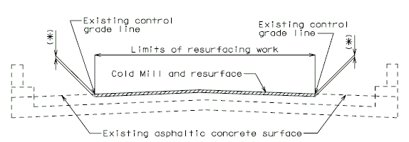 |
| SECTION THRU ROADWAY |
Place the following notes on plans.
- The existing asphaltic concrete surface shall be removed to a uniform grade line * below the existing control grade line as noted.
- Resurface with * Asphaltic Concrete.
- * Depth of asphaltic concrete as specified in the Bridge Memorandum.
751.40.2.2 Special Repair Zones
The following order of repair zones shall be used for the deck repair on continuous concrete structures.
Hydro Demolition Projects (Case 1 and 2)
Conventional deck repair required in the areas designated as special repair zones shall be completed before demolition in alphabetical sequence beginning with Zone A. Zones with the same letter designation may be repaired at the same time.
Any deck repair in areas not designated as a special repair zone shall be completed after hydro demolition. Case 1 is primarily monolithic deck repair after hydro demolition. Case 2 is primarily conventional deck repair after hydro demolition.
Note:
- - Case 1 shall not be used for polyester polymer and low slump concrete wearing surfaces (too stiff for monolithic repairs).
- - Conventional deck repair is required with void tube replacement after hydro demolition with both Case 1 and Case 2.
- - If an excessive number of zones are required at any bent, see the Structural Project Manager or Structural Liaison Engineer.
- - Consider combining zones if the length of a zone in the longitudinal direction of the bridge is less than 24 inches.
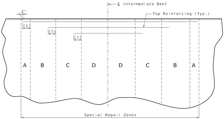 |
| PART PLAN OF SLAB SHOWING REPAIR ZONES (A, B, C and D) |
- (1) Development Length.
- See EPG 751.50 Standard Detailing Notes for appropriate notes.
Non-Hydro Demolition Projects
Any deck repair in areas not designated as a special repair zone shall be completed prior to work in Zone A. Zones with the same letter designation may be repaired at the same time.
Note:
- - If an excessive number of zones are required at any bent, see the Structural Project Manager or Structural Liaison Engineer.
- - Consider combining zones if the length of a zone in the longitudinal direction of the bridge is less than 24 inches.
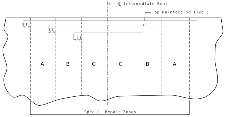 |
| PART PLAN OF SLAB SHOWING REPAIR ZONES (A, B and C) |
- (1) Development Length.
- See EPG 751.50 Standard Detailing Notes for appropriate notes.
751.40.2.3 Deck Repair and Filled Joints
Bridge Deck, Repair
Report 2002
See also: Research Publications
| Bridge Standard Drawings |
| Rehabilitation, Surfacing & Widening – RHB; Deck Rehab (Deck Repair and Wearing Surface Details) |
751.40.2.4 Wearing Surfaces
Replacement of Typical Expansion Joint Systems (Strip Seal Shown, Other Systems Similar)
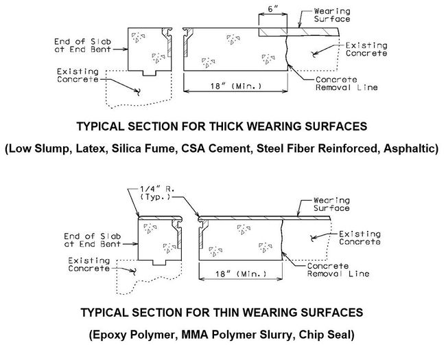
When concrete is removed and armor is replaced, see EPG 751.13 Expansion Joint Systems for the appropriate expansion joint system details and EPG 751.50 H5 for the appropriate notes.
For chip seals and polymer wearing surfaces, see EPG 751.50 I1 for the appropriate notes.
Elastomeric Expansion Joint System
When a thick wearing surface (low slump, latex, silica fume, CSA cement, steel fiber reinforced, asphaltic) is used, the elastomeric joint must be replace by another type of expansion joint system.
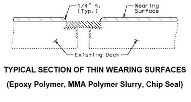
Flat Plate Expansion Joint System
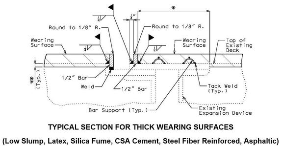
- * When this dimension exceeds 3" and a concrete wearing surface is used, tack weld a one inch bar chair to the plate for each 3" of plate to be covered by the wearing surface.
- ** Scarify existing slab. See the Bridge Memorandum for the minimum depth of scarification. Scarification not required for asphaltic concrete wearing surface.
- Note: See standard plans for Steel Dams at Expansion Joints.
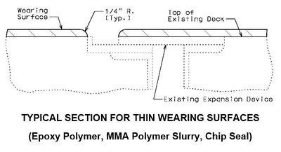
751.40.2.5 Edge Treatments
751.40.2.5.1 Epoxy Coating
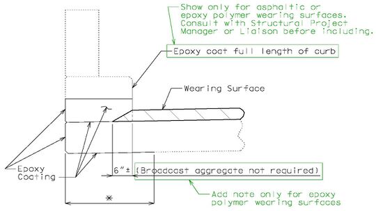 |
| TYPICAL SECTION OF EXISTING CURB OUTLET SHOWING LIMITS OF EPOXY COATING |
- Note:
- * Dimension to edge of girder or stringer ±. For bridges that do not have girders or stringers use 2'-6", except that if with thrie beam rail, then use 4'-0".
- Consult with Structural Project Manager or Liaison for making work incidental to another item or use of pay item "Cleaning and Epoxy Coating".
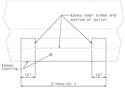
|
| TYPICAL ELEVATION OF EXISTING CURB OUTLET SHOWING LIMITS OF EPOXY COATING (Wearing surface not shown for clarity) |
751.40.2.5.2 Edge Repair
If slab edge repair is specified on the Bridge Memorandum when the barrier or railing is not removed or when full depth repair is not a pay item, the following detail shall be provided.
 |
| CONCRETE EDGE REPAIR |
- If the barrier or railing is removed when full depth repair and slab edge repair are pay items, the following detail shall be provided.
 |
| CONCRETE EDGE REPAIR |
- * If the dimension exceeds 4 inches, the repair extending to the edge of slab will be paid for as Full Depth Repair.
751.40.2.6 Longitudinal Joints
REPLACEMENT OF EXISTING EXPANSION DEVICE
MEDIAN BARRIER
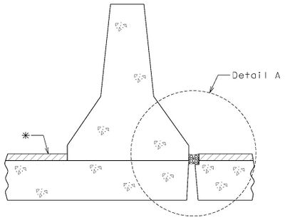 |
| SECTION THRU BARRIER |
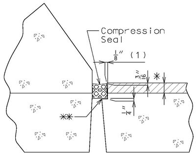 |
| DETAIL A |
- (1) May be cast vertical and saw cut to slant.
- * Latex Concrete Wearing Surface = 1-3/4".
Low Slump Concrete Wearing Surface = 2-1/4". - ** Cut minimum 1/2" support notch (rough finish). Remove any existing compression seal.
751.40.2.7 Temporary Traffic Control Device
Show Barrier as per district recommendation. Typically Barrier is shown when structure is on interstate and/or the rail is being removed. Otherwise, show the dimension lines with 2'-0" dimension.

- * If this dimension is less than 3 feet, the temporary concrete traffic barrier shall be attached with tie-down straps, with the approval of the Structural Project Manager or Structural Liaison Engineer. Where lateral deflection cannot be tolerated, the temporary concrete traffic barrier shall be attached with the bolt through deck detail (to be used only on existing decks). See EPG 617.1 Temporary Traffic Barriers and EPG 751.1.2.12 Temporary Barriers.
- ** Where slab removal represents small and discontinuous openings in the deck along the bridge length (e.g. expansion device replacement) use of either a flat steel plate, a 22 ½” temporary traffic control device or a temporary concrete traffic barrier may be more appropriate. Consult with the Structural Project Manager or Structural Liaison Engineer.
751.40.3 Substructure Repair
751.40.3.1 Formed and Unformed Repair Areas
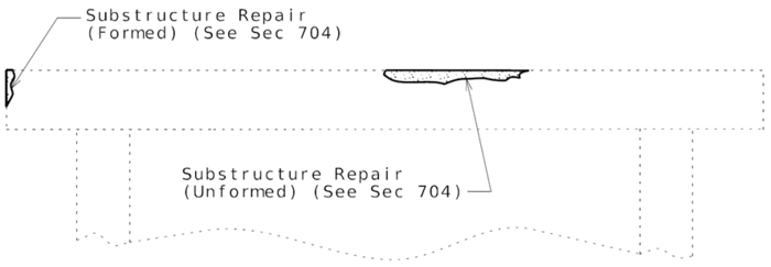 |
| Elevation of Int. Bent |
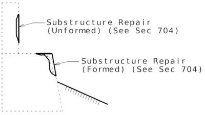 |
| Section through End Bent |
751.40.3.2 Bent Cap Shear Strengthening using FRP Wrap
| Bridge Standard Drawings |
| Rehabilitation, Surfacing & Widening; Fiber Reinf. Polymer (FRP) Wrap for Bent Cap Strengthening [RHB08] |
Fiber Reinforced Polymer (FRP) wrap may be used for Bent Cap Shear Strengthening.
When to strengthen: When increased shear loading on an existing bent cap is required and a structural analysis shows insufficient bent cap shear resistance, bent cap shear strengthening is an option. An example of when strengthening a bent cap may be required: removing existing girder hinges and making girders continuous will draw significantly more force to the adjacent bent. An example of when strengthening a bent cap is not required: redecking a bridge where analysis shows that the existing bent cap cannot meet capacity for an HS20 truck loading, and the new deck is similar to the old deck and the existing beam is in good shape.
How to strengthen: Using FRP systems for shear strengthening follows from the guidelines set forth in NCHRP Report 678, Design of FRP System for Strengthening Concrete Girders in Shear. The method of strengthening, using either discrete strips or continuous sheets, is made optional for the contractor in accordance with NCHRP Report 678. A Bridge Standard Drawing and Bridge Special Provision have been prepared for including this work on jobs. They can be revised to specify a preferred method of strengthening if desired, strips or continuous sheet.
What condition of existing bent cap required for strengthening: If a cap is in poor shape where replacement should be considered, FRP should not be used. Otherwise, the cap beam can be repaired before applying FRP. Perform a minimum load check using (1.1DL + 0.75(LL+I))* on the existing cap beam to prevent catastrophic failure of the beam if the FRP fails (ACI 440.2R, Guide for the Design and Construction of Externally Bonded FRP, Sections 9.2 and 9.3.3). If the factored shear resistance of the cap beam is insufficient for meeting the factored minimum load check, then FRP strengthening should not be used.
- * ACI 440.2R: Guide for the Design and Construction of Externally Bonded FRP
Design force (net shear strength loading): Strengthening a bent cap requires determining the net factored shear loading that the cap beam must carry in excess of its unstrengthened factored shear capacity, or resistance. The FRP system is then designed by the manufacturer to meet this net factored shear load, or design force. The design force for a bent cap strengthening is calculated considering AASHTO LFD where the factored load is the standard Load Factor Group I load case. To determine design force that the FRP must carry alone, the factored strength of the bent cap, which is 0.85 x nominal strength according to LFD design, is subtracted out to give the net factored shear load that the FRP must resist by itself. NCHRP Report 678 is referenced in the special provisions as guidelines for the contractor and the manufacturer to follow. The report and its examples use AAHTO LRFD. Regardless, the load factor case is given and it is left to the manufacturer to provide for a satisfactory factor of safety based on their FRP system.
Other References:
- * ACI 201.1R: Guide for Making a Condition Survey of Concrete in Service
- * ACI 224.1R: Causes, Evaluation, and Repair of Cracks in Concrete
- * ACI 364.1R-94: Guide for Evaluation of Concrete Structures Prior to Rehabilitation
- * ACI 440.2R-08: Guide for the Design and Construction of Externally Bonded FRP Systems for Strengthening Concrete Structures
- * ACI 503R: Use of Epoxy Compounds with Concrete
- * ACI 546R: Concrete Repair Guide
- * International Concrete Repair Institute (ICI) ICI 03730: Guide for Surface Preparation for the Repair of Deteriorated Concrete Resulting from Reinforcing Steel Corrosion
- * International Concrete Repair Institute (ICI) ICI 03733: Guide for Selecting and Specifying Materials for Repairs of Concrete Surfaces
- * NCHRP Report 609: Recommended Construction Specifications Process Control Manual for Repair and Retrofit of Concrete Structures Using Bonded FRP Composites
751.40.3.3 Steel HP Pile Maintenance and Repair
Maintenance/Repair Guidelines
Piles are primary structural members and are compressively loaded all the time which makes it important to safely inspect, maintain and repair them if necessary. Pile inspection will require an assessment of pile performance by looking for pile deterioration and measuring pile section loss in order to determine the level of pile maintenance/repair required. The following schedule may be used for selecting the level of maintenance/repair required:
| Pile Percent Section Loss | Method* | Level |
|---|---|---|
| 0% through 25% | Clean and recoat existing piles | Maintenance |
| >25% through 40% | Encasement of deteriorated section | Maintenance |
| >40% through 75% or holes in any element or local buckling of any element | Plating ** of deteriorated section OR replacement *** of section (splicing), AND encasement of the repaired section | Repair |
| >75% | Contact the Bridge Division | Repair |
| * Method may also include cleaning and recoating all exposed piles, and cleaning and recoating all remaining exposed pile sections after encasement and/or repair. | ||
| ** Plating can be for both flanges only, web only or both flanges and web. Overall symmetry of the pile cross-section shall be maintained when plating. | ||
| *** Based on additional factors other than just the percent of pile section loss, a replacement pile section (splicing) may be considered. Minimizing or eliminating traffic loading, adding falsework or just having support conditions such as integral bents (where both the pile cap beam and the superstructure concrete diaphragm are connected by more than just dowel bars – see bridge plans) can help to determine the method of repair. A replacement pile section can be coated or galvanized. See Structural Project Manager. | ||
Estimating Pile Percent Section Loss in the Field
Quantifying pile section loss can be inexact. To encourage uniform application of the maintenance/repair guidelines, the following procedure is recommended:
- 1. Pile section loss should be determined using a thickness meter.
- 2. Remove deteriorated material and clean pile for measurement.
- 3. At any point along a pile (cross-section) where there are three elements to be considered independently, e.g. two flanges and a web.
- 4. Estimate the actual cross-section area of each element at its most deteriorated point along the length of pile. Using the thickness meter, measure the thickness at several points along a horizontal line across the element. From this data, estimate the actual cross-section area of each element.
- 5. The fraction of section remaining (PSR) is the actual cross-section area of each element at its most deteriorated point along the length of pile divided by the original area of same element.
- 6. Percent section loss is 100(1 – PSR) for each element.
- 7. The greatest PSR dictates the maintenance/repair method.
- 8. Examine continuity at flange/web intersections. Section loss along these intersections along the length of pile of more than 6 linear inches should be repaired using encasement as either the only method or part of plating/replacing repair method regardless of a low percent section loss.
- 9. Interference from cross bracing at pile sections to be repaired will need special consideration not detailed on the standard drawings.
| Bridge Standard Drawings |
| Rehabilitation, Surfacing & Widening – RHB; Steel HP Pile Maintenance and Repair |
Additional types of maintenance and repairs may be considered which include but are not limited to:
- Zinc tape coating
- FRP strengthening
- Corrosion inhibitor
751.40.4 Barriers and Railings
751.40.4.1 End Post Modification for 12-inch Vertical Barrier (Safe & Sound Bridges)
The 12-inch vertical barrier requires modification to allow attachment of the transition for the Midwest Guardrail System.
| Bridge Standard Drawings |
| Barrier End Modifications – BEM & CBO/Barrier End Modification – BEM |
751.40.4.2 Replacement of Existing Type B Barrier Using Anchor Systems
NEW BARRIER ON SLAB

|
| SECTION THRU BARRIER |

|
| SECTION THRU BARRIER (OPTIONAL ANCHORING SYSTEM) |
| See EPG 751.50 I2. Resin & Cone Anchors for appropriate notes. |
NEW BARRIER ON WING

|
| SECTION THRU BARRIER(*) |

|
| SECTION THRU BARRIER(*) (OPTIONAL ANCHORING SYSTEM) |
- Note: See EPG 751.50 I2. Resin & Cone Anchors for appropriate notes. For details not shown, see EPG 751.12 Barriers, Railings, Curbs and Fences.
REPLACEMENT OF EXISTING BARRIER AT END OF WING USING ANCHOR SYSTEMS
INTEGRAL END BENTS
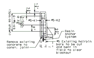 |
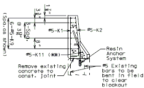 |
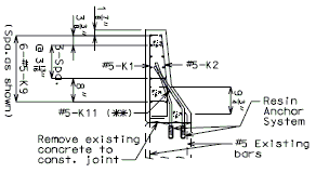
|
| SECTION A-A | SECTION B-B | SECTION C-C |
REPLACEMENT OF EXISTING BARRIER AT END OF WING USING ANCHOR SYSTEMS
NON-INTEGRAL END BENTS
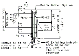 |
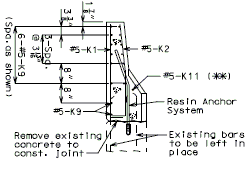 | | 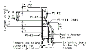
| |
| SECTION A-A | SECTION B-B | SECTION C-C |
751.40.4.3 Replacement of Existing Rail with Thrie Beam Rail
As a matter of policy, blockouts for thrie beam railings are required while FHWA does show similar systems without blockouts as NCHRP 350 approved. See the Structural Project Manager (SPM) or the Structural Liaison Engineer (SLE), if practical, to omit blockout. A design exception shall be required. Blockouts shall always be required on major routes.
There are four systems for use on state routes. In these four systems the connection design load used is 1.5 times plastic moment capacity (Mp) of W6 x 20 Post. The vertical clearance of System 3 shall be checked due to the obtruding lower connection.
| Bridge Standard Drawings |
| Thrie Beam Rails - THRIE |
751.40.4.4 End Treatment Using Thrie Beam Rail
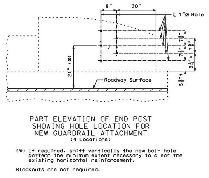
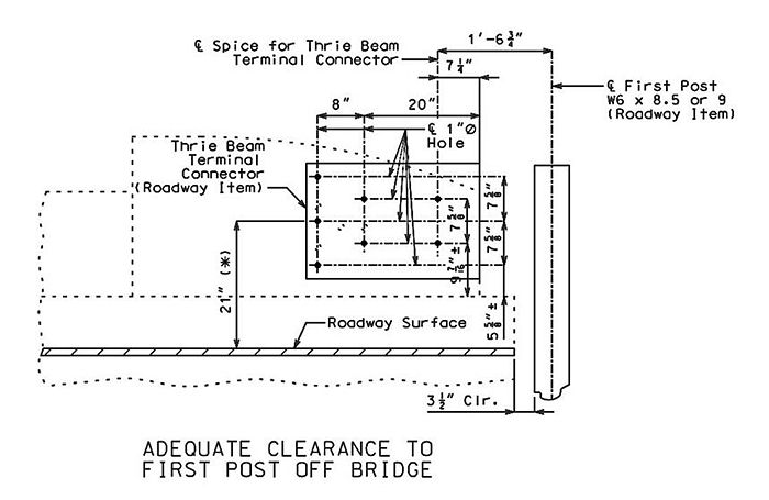
Guidance for Design:
- Adequate clearance to first post off bridge shall be required. (See also Standard Plan 617.10 for new bridges.)
751.40.4.5 Curb Blockouts
See EPG 751.1.3.4 Barrier or Railing Type, Height and Guidelines for Curb Blockouts for usage guidance.
| Bridge Standard Drawings |
| Barrier Modifications – BEM & CBO/Curb Blockouts - CBO |
751.40.5 Drainage
751.40.5.1 Structure with Wearing Surface Slab Drains - Details
Two material options may be used for slab drains:
- 1. Steel Slab Drains and inserts are only shown in the following details.
- 2. Fiberglass Reinforced Polymer (FRP) drains may be used with the approval of the Structural Project Manager or Structural Liaison Engineer. See EPG 751.10.3.2.1 New Structure Without Wearing Surface Slab Drains - Details for guidance and details of FRP drains on new structures as an aid.
- A positive mechanical connection must be used for attaching FRP drains to either existing steel drains or to new FRP inserts since welding cannot be used as is shown in the following details for steel drains. For example, using at least four bolt-through connectors (one per side) from new FRP drains into a new wearing surface or an existing steel drain, or using an epoxy adhesive in conjunction with at least two bolt-through connectors is required. It has been shown that using a more viscous epoxy or anchoring gel is beneficial in order to avoid dripping during placement. Using epoxy adhesive or an anchoring gel by itself is not acceptable.
- FRP drain may not fit exactly to the inside or to the outside of existing steel drain. The looseness of fit can be addressed by considering a combination of attachment details like mechanical connectors (to existing slab drain) plus either a viscous epoxy adhesive or a positive attachment to an exterior girder depending on the length of the slab drain extension.
For new wearing surface over new slab, note on plans:
- Piece "A" shall be cast in the concrete slab. Prior to placement of wearing surface, piece "B" shall be inserted into piece "A".
FOR STRUCTURE WITH WEARING SURFACE
(GIRDER DEPTH LESS THAN 48")


| * | Deck thickness minus 1/8" minus the depth of the scarification. |
| ** | Do not include the depth of the scarification. |

FOR STRUCTURE WITH WEARING SURFACE
(GIRDER DEPTH 48" AND OVER)
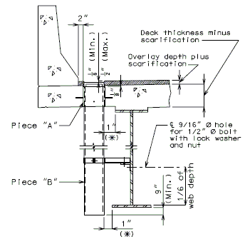
|
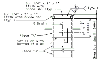
|
| ELEVATION OF DRAIN | |
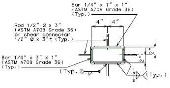
| |
| PART ELEVATION OF SLAB AT DRAIN | PLAN OF DRAIN |
* If dimension is less than 1", drains shall be placed parallel to roadway. Otherwise, place drains transverse to roadway. ** Do not include the depth of the scarification. *** Deck thickness minus 1/8" minus the depth of the scarification.
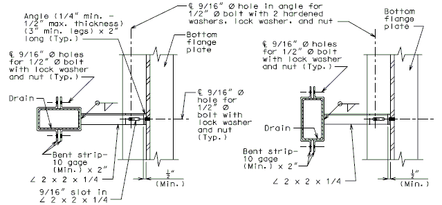
| |
| DRAIN TRANSVERSE TO ROADWAY | DRAIN PARALLEL TO ROADWAY |
| PART PLANS SHOWING BRACKET ASSEMBLY | |
FOR STRUCTURE WITH WEARING SURFACE
(CONTINUOUS CONCRETE STRUCTURES)
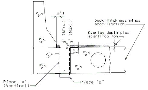
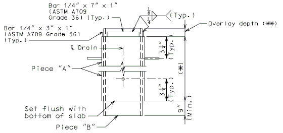
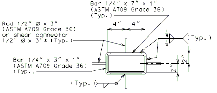
| * | Deck thickness minus 1/8" minus the depth of the scarification. |
| ** | Do not include the depth of scarification. |
FOR STRUCTURE WITH WEARING SURFACE
(VARIABLE DEPTH GIRDERS)

Note: For variable depth girders with drains in deeper section, let the deeper section control and use throughout the structure.

751.40.5.2 Structure with Wearing Surface Round Slab Drains - Details
FOR STRUCTURE WITH WEARING SURFACE
MISCELLANEOUS DETAILS - ROUND DRAINS
FRP round drains may be used optionally unless otherwise specified. See EPG 751.10.3 Bridge Deck Drainage – Slab Drains for guidance and details as an aid. Specify nominal pipe size as needed referencing ASTM D2996. Specify outer diameter based on nominal pipe size necessary for drainage for coring the correct size hole in deck.
Note: See EPG 751.10.3 Bridge Deck Drainage – Slab Drain for slab drain spacing.
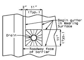 |
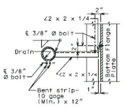 |
| TYPICAL PART PLAN | SECTION SHOWING BRACKET ASSEMBLY |

751.40.5.3 Structure with Wearing Surface Raising Slab Drains or Scuppers - Details
FOR STRUCTURE WITH WEARING SURFACE
RAISING SLAB DRAINS


Outside dimensions of drain extension are 7-1/4" x 3-1/4", and drain extension shall be galvanized in accordance with ASTM A123.
FOR STRUCTURE WITH WEARING SURFACE
RAISING SCUPPERS


AND
PLAN OF SCUPPER EXTENSION
751.40.5.4 Cored Slab Drains
Cored slab drains may be installed in areas where the existing drainage is a concern, but the deck is not in need of replacement. Typically, 4-inch diameter drains are installed vertically to avoid the deck reinforcing steel which is typically spaced at 5-inch centers. If necessary, larger diameter drains or angled drains may be used with approval of the SPM or SLE.
| Bridge Standard Drawings |
| Rehabilitation, Surfacing & Widening - RHB/Cored Slab Drain for Existing Bridge Deck [RHB18] |
751.40.6 Closure Pour
Note:
For closure pour on solid slab or voided slab bridges, use expansive concrete.
Release the forms before the closure pour is placed.

751.40.7 Design and Posting Considerations
Existing structures to redecked and/or widened should be evaluated to determine if the superstructure is considered to be structurally adequate. The structural adequacy check should be determined based on load ratings using the Load Factor Method. Strengthening of the superstructure will not be required if the minimum posting values shown below meet or exceed legal load requirements. In addition, there may be cases where the existing bridge posting is acceptable based on the bridge specific site conditions such as AADT, amount of truck traffic, overweight permit route, etc.
| 1) | H20 (one lane with Impact) [Posting Rating] ≥ 23 tons |
| 2) | 3S2 (one lane with impact) [Posting Rating] ≥ 40 tons |
Posting Rating = 86% of Load Factor Operating Rating (Refer to figures below for H20, 3S2 and MO5 criteria).
If a structure is located within a commercial zone, then the following additional posting condition must be investigated:
| 3) | M05 (two lane with impact) [Operating Rating] ≥ 70 Tons (posting limit) |
Any other overstresses or inadequacies (slab, substructure, etc.) shall be reported to the Structural Project Manager.
Deck thickness for redecks shall be determined such that Posting will not be required or the existing posting is not lowered, and it is generally not less than original deck thickness.
Deck thickness for widenings shall be existing thickness unless thicker slab does not create overall deck stiffening irregularities.
See Structural Project Manager if AASHTO minimum deck thickness can not be used on redecks and widenings.
Future Wearing Surface (FWS) Loadings for widenings with concrete wearing surfaces - In addition to weight of wearing surface:
- Add FWS of 35 psf to the design of new girders if existing girders are sufficient for the 35 psf FWS
- Lower FWS loading to 15 psf if existing girders are not sufficient for FWS loading of 35 psf
- If existing girders are not sufficient for any FWS then lower FWS to FWS = 0.
- The existing ratings should be reviewed to determine what wearing surface loads were used. When necessary, the rating should be evaluated for acceptability of the proposed changes in the wearing surface loads and geometry. Preliminary ratings that are based on estimated geometry shall be revised when the updated, final geometry is known.
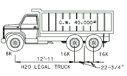
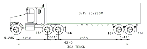
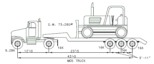
751.40.8 Design Information when using AASHTO Standard Specifications for Highway Bridges 17th Edition
751.40.8.1 Loadings
751.40.8.1.1 Live Load
Structures shall be designed to carry the dead load, live load, impact (or dynamic effect of the live load), wind load and other forces, when they are applicable.
Members shall be designed with reference to service loads and allowable stresses as provided in AASHTO (17th edition) Service Load Design Method (Allowable Stress Design) or with reference to factored load and factored strength as provided in AASHTO Strength Design Method (Load Factor Design). Load groups represent various combination of loads and forces to which a structure may be subjected. Group loading combinations for Service Load Design and Load Factor Design are given by AASHTO (17th edition) 3.22.1 and AASHTO (17th edition) Table 3.22.1A.
The live load shall consist of the applied moving load of vehicles and pedestrians. The design live load to be used in the design of bridges for the state system will be as stated on the Bridge Memorandum.
- The design truck: HS20-44 or HS20-44 Modified
- The design tandem (Military)
- The design lane loading
Criteria
- All widened or retrofitted bridges on the National Highway System and in commercial zones may be designed for HS20-44 Modified loading. All remaining bridges will be designed for HS20-44 loading.
- The Design Tandem loading is to be checked on national highway system or when Alternate Military loading appears on the Bridge Memorandum.
- Carrying members of each structure shall be investigated for the appropriate loading.
- Main carrying members include:
- Steel or Concrete stringers or girders.
- Longitudinally reinforced concrete slabs supported on transverse floor beams or substructure units (includes hollow slabs).
- Transversely reinforced concrete slabs supported by main carrying members parallel to traffic and over 8'-0" center to center. Use the formulas for moment in AASHTO Article 3.24.3.1 Case A.
- Steel grid floors when the main elements of the grid extend in a direction parallel to traffic, or with main elements transverse to traffic on supports more than 8'-0" apart.
- Timber floors and orthotropic steel decks.
- Main carrying members include:
- The reduction in live load for calculating substructure members is based on AASHTO 3.12.1. See Live Load Distribution in the Load Distribution Section.
HS20-44 Truck Loading
The HS20-44 truck is defined below as one 8 kip axle load and two 32 kip axle loads spaced as shown.
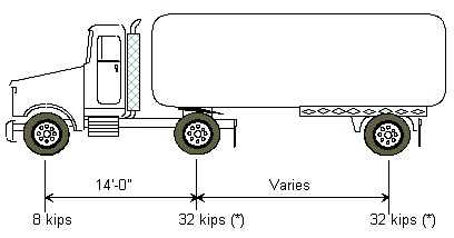
Varies = Variable spacing 14’ to 30’ inclusive. Spacing to be used is that which produces the maximum stresses.
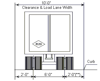
(*) In the design of timber floors and orthotropic steel decks (excluding transverse beams) for H-20 Loading, one axle load of 24 kips or two axle loads of 16 kip each, spaced 4 feet apart may be used, whichever produces the greater stress, instead of the 32 kip axle load shown.
(**) For slab design, the center line of wheels shall be assumed to be one foot from face of cur
HS20-44 Modified Truck Loading
The HS20-44 Modified truck is defined below as one 10 kip axle load and two 40 kip axle loads spaced as shown. This is the same as HS20-44 truck modified by a factor of 1.25.
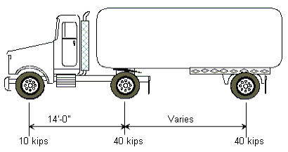
Varies = Variable spacing 14’ to 30’ inclusive. Spacing to be used is that which produces the maximum stresses.
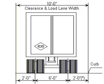
(*) For slab design, the center line of wheels shall be assumed to be one foot from face of curb.
Design Tandem Loading
The Design Tandem Loading is a two axle load each of 24 kips. These axles are spaced at 4'-0" centers. The transverse spacing of wheels shall be taken as 6'-0".
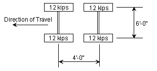
Design Lane Loading
- For HS20-44 Truck, the design lane load shall consist of a load 640 lbs per linear foot, uniformly distributed in the longitudinal direction with a single concentrated load (or two concentrated loads in case of continuous spans for determination of maximum negative moment), so placed on the span as to produce maximum stress. The concentrated load and uniform load shall be considered as uniformly distributed over a 10'-0" width on a line normal to the center line of the lane.
- For HS20-44 Modified Truck, use the HS20-44 truck modified by a factor of 1.25.

- For the design of continuous structures, an additional concentrated load is placed in another span to create the maximum effect. For positive moments, only one concentrated load is used, combined with as many spans loaded uniformly as are required to produce the maximum moment.
Standard Roadway Width
- 26'-0" (up to 2 traffic lanes)
- 28'-0" (up to 2 traffic lanes)
- 30'-0" (up to 3 traffic lanes)
- 32'-0" (up to 3 traffic lanes)
- 36'-0" (up to 3 traffic lanes)
- 38'-0" (up to 3 traffic lanes)
- 40'-0" (up to 4 traffic lanes)
- 44'-0" (up to 4 traffic lanes)
751.40.8.1.2 Impact
Highway live loads shall be increased by a factor given by the following formula:
in feet
For continuous spans, to be used in this equation for negative moments is the average of two adjacent spans at an intermediate bent or the length of the end span at an end bent. For positive moments, is the span length from center to center of support for the span under consideration.
Impact is never to be more than 30 percent. It is intended that impact be included as part of the loads transferred from superstructure to substructure but not in loads transferred to footings or parts of substructure that are below the ground line. The design of neoprene bearing pads also does not include impact in the design loads.
751.40.8.1.3 Collision Force
Collision forces shall be applied to the barrier or railing in the design of the cantilever slab. A force of 10 kips is to be applied at the top of the standard barrier or railing. This force is distributed through the barrier or railing to the slab.
751.40.8.1.4 Centrifugal Force
Structures on curves shall be designed for a horizontal radial force equal to the following percentage of the live load in all the lanes, without impact.
Where:
| = the centrifugal force in percent of the live load | |
| = the design speed in miles per hour | |
| = the radius of the curve in feet |
This force shall be applied at 6 feet above the centerline of the roadway with one design truck being placed in each lane in a position to create the maximum effect. Lane loads shall not be used in calculating centrifugal forces.
The effects of superelevation shall be taken into account.
751.40.8.1.5 Lateral Earth Pressure
Structures which retain fills shall be designed for active earth pressures as
Where:
| = active earth pressure per length (lb/ft) | ||
| = unit weight of the back fill soil = 120 lb/ft³ | ||
| = coefficient of active earth pressure as given by Rankine’s formula | ||
| = | = equivalent fluid pressure (lb/ft³)(*) | |
| = height of the back fill soil (ft) | ||
Rankine's Formula
The coefficient of active earth pressure is:
Where:
| = angle of internal friction of the backfill soil (*) | |
| = the angle of incline of the backfill |
If the backfill surface is level, angle a is zero and is:
(*) Use the internal friction angle indicated on the Bridge Memorandum. However, if the friction angle is not determined, use the minimum equivalent fluid pressure value, , of 45 lb/ft³ for bridges and retaining walls. For box culverts use a maximum of 60 lb/ft³ and a minimum of 30 lb/ft³ for fluid pressure.
Live Load Surcharge
An additional earth pressure shall be applied to all structures which have live loads within a distance of half the structure height. This additional force shall be equal to adding 2'-0" of fill to that presently being retained by the structure.
751.40.8.1.6 Longitudinal Forces (Braking Forces)
A longitudinal force of 5% of the live load shall be applied to the structure. This load shall be 5% of the lane load plus the concentrated load for moment applied to all lanes and adjusted by the lane reduction factor. Apply this force at 6 feet above the top of slab and to be transmitted to the substructure through the superstructure.
751.40.8.1.7 Wind Load
Wind loads shall be applied to the structure regardless of length.
The pressure generated by wind load is:
Where:
| = wind pressure in pounds per square foot | |
| = design wind velocity = 100 miles per hour | |
| = 0.004 for wind load |
Basic wind load (pressure) = 0.004 x (100)² = 40 lb/ft²
Wind Load for Superstructure Design
Transverse
A wind load of the following intensity shall be applied horizontally at right angles to the longitudinal axis of the structure.
- Trusses and Arches = 75 pounds per square foot =
- Girders and Beams = 50 pounds per square foot (*) = (for plate girder lateral bracing check only)
- The total force shall not be less than 300 pounds per linear foot in the plane of windward chord and 150 pounds per linear foot in the plane of the leeward chord on truss spans, and not less than 300 pounds per linear foot on girder spans.
Wind Load for Substructure Design
Forces transmitted to the substructure by the superstructure and forces applied directly to the substructure by wind load shall be as follows:
Forces from Superstructure: Wind on Superstructure
Transverse
A wind load of the following intensity shall be applied horizontally at right angles to the longitudinal axis of the structure.
- Trusses and Arches = 75 pounds per square foot =
- Girders and Beams = 50 pounds per square foot (*) =
(*) Use Wt = 60 lbs/ft² for design wind force on girders and beams If the column height on a structure is greater than 50 feet, where the height is the average column length from ground line to bottom of beam.
The transverse wind force for a bent will be:
Where:
| = length in feet = the average of two adjacent spans for intermediate bents and half of the length of the end span for end bents. | |
| = the total height of the girders, slab, barrier or raling and any superelevation of the roadway, in feet | |
| = wind force per unit area in pounds per square foot |
This transverse wind force will be applied at the top of the beam cap for the design of the substructure.
Longitudinal (**)
The standard wind force in the longitudinal direction shall be applied as a percentage of the transverse loading. Use approximately 25%.
Truss and Arch Structures = 75 x 0.25 = approximately 20 lbs/ft² Girder Structures = 50 x 0.25 = approximately 12 lbs/ft²
The total longitudinal wind force will be:
Where:
| = the overall bridge length in feet | |
| = the total height of the girders, slab, barrier or railing and anysuperelevation of the roadway, in feet | |
| = wind force per unit area in pounds per square foot |
This longitudinal force is distributed to the bents based on their stiffness. (**)
The longitudinal wind force for the bent will be applied at the top of the beam cap for the design of the substructure.
Forces from Superstructure: Wind on Live Load
A force of 100 pounds per linear foot of the structure shall be applied transversely to the structure along with a force of 40 pounds per linear foot longitudinally. These forces are assumed to act 6 feet above the top of slab. The transverse force is applied at the bents based on the length of the adjacent spans affecting them. The longitudinal force is distributed to the bents based on their stiffness. (**)
(**) See EPG 751.2.4.6 Longitudinal Wind Force Distribution.
Forces Applied Directly to the Substructure
The transverse and longitudinal forces to be applied directly to the substructure elements shall be calculated from an assumed basic wind force of 40 lbs/ft². This wind force per unit area shall be multiplied by the exposed area of each substructure member in elevation (use front view for longitudinal force and side view for transversely force, respectively). These forces are acting at the center of gravity of the exposed portion of the member.
A shape factor of 0.7 shall be used in applying wind forces to round substructure members.
When unusual conditions of terrain or the special nature of a structure indicates, a procedure other than the Standard Specification may be used subject to approval of the Structural Project Manager.
751.40.8.1.8 Temperature Forces
Temperature stresses or movement need to be checked on all structures regardless of length. Generation of longitudinal temperature forces is based on stiffness of the substructure. (*)
Coefficients
Steel: Thermal - 0.0000065 ft/ft/°F Concrete: Thermal - 0.0000060 ft/ft/°F Shrinkage - 0.0002 ft/ft (***) Friction - 0.65 for concrete on concrete
| Rise | Fall | Range | |
| Steel Structures | 60°F | 80°F | 140°F |
| Concrete Structures | 30°F | 40°F | 70°F |
(*) See EPG 751.2.4.7 Longitudinal Temperature Force Distribution.
(**) Temperature Range for expansion bearing design and expansion devices design see EPG 751.11 Bearings and EPG 751.13 Expansion Devices, respectively.
(***) When calculating substructure forces of concrete slab bridges, the forces caused by the shrinkage of the superstructure should be included with forces due to temperature drop. This force can be ignored for most other types of bridges.
751.40.8.1.9 Sidewalk Loading
Sidewalk floors and their immediate support members shall be designed for a live load of 85 pounds per square foot of sidewalk area. Girders, trusses, and other members shall be design for the following sidewalk live load:
Spans 0 to 25 feet 85 lbs/ft² Spans 26 to 100 feet 60 lbs/ft² Spans over 100 feet use the following formula
Where:
| = live load per square foot, max. 60 lbs/ft² | |
| = loaded length of sidewalk in feet | |
| = width of sidewalk in feet |
When sidewalk live loads are applied along with live load and impact, if the structure is to be designed by service loads, the allowable stress in the outside beam or stringer may be increased by 25 percent as long as the member is at least as strong as if it were not designed for the additional sidewalk load using the initial allowable stress. When the combination of sidewalk live load and traffic live load plus impact governs the design under the load factor method, use a b factor of 1.25 instead of 1.67.
Unless a more exact analysis can be performed, distribution of sidewalk live loads to the supporting stringers shall be considered as applied 75 percent to the exterior stringer and 25 percent to the next stringer.
751.40.8.1.10 Other Loads
Stream Pressure
Stream flow pressure shall be considered only in extreme cases. The affect of flowing water on piers shall not be considered except in cases of extreme high water and when the load applied to substructure elements is greater than that which is applied by wind on substructure forces at low water elevations.
The pressure generated by stream flow is:
Where:
| = stream pressure in pounds per square foot | |
| = design velocity of water in feet per second | |
| = shape constant for the surface the water is in contact with. | |
| = 1.4 for square-ended piers | |
| = 0.7 for circular piers | |
| = 0.5 for angle-ended piers where the angle is 30 degrees or less |
Ice Forces
Ice forces on piers shall be applied if they are indicated on the Bridge Memorandum.
Buoyancy
Buoyancy shall be considered when its effects are appreciable.
Fatigue in Structural Steel
Steel structures subjected to continuous reversal of loads are to be designed for fatigue loading.
Prestressing
See EPG 751.22 P/S Concrete I Girders.
Other Loads
Other loads may need to be applied if they are indicated on the Bridge Memorandum. Otherwise see Structural Project Manager before applying any additional loads.
751.40.8.1.11 Group Loads
Group Loading (Service Load Design)
Group loading combinations are:
GP I SL 100% GP II SL 125% GP III SL 125% GP IV SL 125% GP V SL 140% GP VI SL 140%
Where:
| = dead load | |
| = live load | |
| = live load impact | |
| = wind load on structure | |
| = wind load on live load | |
| = temperature force | |
| = longitudinal force from live load |
Group Loading (Load Factor Design)
Group loading combinations are:
GP I LF GP II LF GP III LF GP IV LF GP V LF GP VI LF
Where:
| = dead load | |
| = live load | |
| = live load impact | |
| = wind load on structure | |
| = wind load on live load | |
| = temperature force | |
| = longitudinal force from live load | |
| = coefficient, see AASHTO Table 3.22.1A |
Other group loadings in AASHTO Table 3.22.1A shall be used when they apply.
751.40.8.2 Distribution of Loads
751.40.8.2.1 Distribution of Dead Load
Composite Steel or Prestressed Concrete Structures
The dead load applied to the girders through the slab shall be:
Dead Load 1
Non-composite dead loads should be distributed to girders (stringers) on the basis of continuous spans over simple supports.
Dead Load 2
Composite loads shall be distributed equally to all girders. The following are all Dead Load 2 loads:
- Barrier or railing
- Future wearing surface on slab
- Sidewalks
- Fences
- Protective coatings and waterproofing on slab
Concrete Slab Bridges
Distribute entire dead load across full width of slab.
For longitudinal design, heavier portions of the slab may be considered as concentrated load for entry into the "Continuous Structure Analysis" computer program.
For transverse bent design, consider the dead load reaction at the bent to be a uniform load across entire length of the transverse beam.
751.40.8.2.2 Distribution of Live Load
Live loading to be distributed shall be the appropriate loading shown on the Bridge Memorandum. Applying Live Load to Structure
Superstructure
For application of live load to superstructure, the lane width is considered 12 feet. Each design vehicle has wheel lines which are 6 feet apart and adjacent design vehicles must be separated by 4 feet.
Substructure
To produce the maximum stresses in the main carrying members of substructure elements, multiple lanes are to be loaded simultaneously. The lane width is 12 feet. Partial lanes are not to be considered. Due to the improbability of coincident maximum loading, a reduction factor is applied to the number of lanes. This reduction however, is not applied in determining the distribution of loads to the stringers.
| Number of Lanes | Percent |
|---|---|
| one or two lanes | 100 |
| three lanes | 90 |
| four lanes or more | 75 |
Moment Distribution
Moments due to live loads shall not be distributed longitudinally. Lateral distribution shall be determined from AASHTO Table 3.23.1 for interior stringers. Outside stringers distribute live load assuming the flooring to act as a simple span, except in the case of a span with a concrete floor supported by four or more stringers, then AASHTO 3.23.2.3.1.5 shall be applied. In no case shall an exterior stringer have less carrying capacity than an interior stringer.
Shear Distribution
As with live load moment, the reactions to the live load are not to be distributed longitudinally. Lateral distribution of live load shall be that produced by assuming the flooring to act as simply supported. Wheel lines shall be spaced on accordance with AASHTO 3.7.6 and shall be placed in a fashion which provides the most contribution to the girder under investigation, regardless of lane configuration. The shear distribution factor at bents shall be used to design bearings and bearing stiffeners.
Deflection Distribution
Deflection due to live loads shall not be distributed longitudinally. Lateral distribution shall be determined by averaging the moment distribution factor and the number of wheel lines divided by the number of girder lines for all girders. The number of wheel lines shall be based on 12 foot lanes. The reduction in load intensity (AASHTO Article 3.12.1) shall not be applied.
Deflection Distribution Factor =
Where:
| = number of whole 12 foot lanes on the roadway | |
| = number of girder lines; | |
| = Moment Distribution Factor. |
Example: 38'-0" Roadway (Interior Girder), , ,
Deflection Distribution Factor =
| Roadway Width |
Number Girders |
Girder Spacing |
Exterior Girder | Interior Girder | (1) | ||||
|---|---|---|---|---|---|---|---|---|---|
| Mom. | Shear | Defl. | Mom. | Shear | Defl. | ||||
| 26’-0” | 4 | 7’-6” | 1.277 | 1.133 | 1.139 | 1.364 | 1.667 | 1.182 | 1.071 |
| 28’-0” | 4 | 8’-2” | 1.352 | 1.204 | 1.176 | 1.485 | 1.776 | 1.243 | 1.167 |
| 30’-0” | 4 | 8’-8” | 1.405 | 1.308 | 1.453 | 1.576 | 1.846 | 1.538 | 1.238 |
| 32’-0” | 4 | 9’-2” | 1.457 | 1.400 | 1.479 | 1.667 | 1.909 | 1.584 | 1.310 |
| 36’-0” | 5 | 8’-2” | 1.352 | 1.184 | 1.276 | 1.485 | 1.776 | 1.343 | 1.167 |
| 38’-0” | 5 | 8’-8” | 1.405 | 1.231 | 1.303 | 1.576 | 1.846 | 1.388 | 1.238 |
| 40’-0” | 5 | 9’-0” | 1.440 | 1.333 | 1.520 | 1.636 | 1.889 | 1.618 | 1.286 |
| 44’-0” | 5 | 9’-9” | 1.515 | 1.487 | 1.558 | 1.773 | 1.974 | 1.687 | 1.393 |
Distribution of Live Load to Substructure
For substructure design the live load wheel lines shall be positioned on the slab to produce maximum moments and shears in the substructure. The wheel lines shall be distributed to the stringers on the basis of simple spans between stringers. The number of wheel lines used for substructure design shall be based on 12 foot lanes and shall not exceed the number of lanes times two with the appropriate percentage reduction for multiple lanes where applicable.
In computing these stresses generated by the lane loading, each 12 foot lane shall be considered a unit. Fractional units shall not be considered.
Distribution of Loads to Slabs
For simple spans, the span length shall be the distance center to center of supports but need not be greater than the clear distance plus the thickness of the slab. Slabs for girder and floor beam structures should be designed as supported on four sides.
For continuous spans on steel stringers or on thin flanged prestressed beams (top flange width to thickness ratios > 4.0), the span length shall be the distance between edges of top flanges plus one quarter of each top flange width. When the top flange width to thickness is < 4.0 the span distance shall be the clear span between edges of the top flanges.
When designing the slab for live load, the wheel line shall be placed 1 foot from the face of the barrier or railing if it produces a greater moment.
Bending Moments in Slab on Girders
The load distributed to the stringers shall be:
P20 or P25 = Moment in foot-pounds per-foot width of slab.
Where:
| = effective span length between girders in feet | |
| P20 or P25 | = wheel line load for HS20 or HS20 Modified design Truck in kips. |
For slabs continuous over 3 or more supports, a continuity factor of 0.8 shall be applied.
Main Reinforcement Parallel to Traffic
This distribution may be applied to special structure types when its use is indicated.
Distribution of Live Load to Concrete Slab Bridges
Live load for transverse beam, column and pile cap design shall be applied as concentrated loads of one wheel line. The number of wheel lines used shall not exceed the number of lanes x 2 with the appropriate reduction where applicable.
For slab longitudinal reinforcement design, use live load moment distribution factor of 1/E for a one-foot strip slab with the appropriate percentage reduction.
Where:
| = Width of slab in feet over which a wheel is distributed | |
| = Effective span length in feet. |
For slab deflection, use the following deflection factor for a one-foot strip slab without applying percentage reduction.
Deflection Factor = (Total number of wheel line) / (width of the slab)
751.40.8.2.3 Frictional Resistance
The frictional resistance varies with different surfaces making contact. In the design of bearings, this resistance will alter how the longitudinal forces are distributed. The following table lists commonly encountered materials and their coefficients. These coefficients may be used to calculate the frictional resistance at each bent.
| Frictional Resistance of Expansion Bearings | |||
|---|---|---|---|
| Bearing Type | Coef. | General Data | |
| Type C Bearing | 0.14 | Coef. of sliding friction steel to steel = 0.14
Coef. for pin and rocker
Frictional Force = | |
| 6” Diameter Roller | 0.01 | ||
| Type D Bearing | |||
| Pin Diameter | Rocker Radius | ||
| 2” | 6.5” | 0.0216 | |
| 2” | 7” | 0.0200 | |
| 2” | 7.5” | 0.0187 | |
| 2” | 8” | 0.0175 | |
| 2” | 10.5” | 0.0133 | |
| PTFE Bearing | 0.0600 | ||
The design of a bent with one of the above expansion bearings will be based on the maximum amount of load the bearing can resist by static friction. When this static friction is overcome, the longitudinal forces are redistributed to the other bents.
The maximum static frictional force at a bent is equal to the sum of the forces in each of the bearings. The vertical reaction used to calculate this maximum static frictional force shall be Dead Loads only for all loading cases. Since the maximum longitudinal load that can be experienced by any of the above bearings is the maximum static frictional force, the effects of longitudinal wind and temperature can not be cumulative if their sum is greater than this maximum static frictional force.
Two conditions for the bents of the bridge are to be evaluated.
- Consider the expansion bents to be fixed and the longitudinal loads distributed to all of the bents.
- When the longitudinal loads at the expansion bearings are greater than the static frictional force, then the longitudinal force of the expansion bearings is equal to the dynamic frictional force. It is conservative to assume the dynamic frictional force to be zero causing all longitudinal loads to be distributed to the remaining bents.
751.40.8.3 Unit Stresses
751.40.8.3.1 Fatigue in Structural Steel
Steel structures subjected to continuous reversal of loads are to be designed for fatigue loading.
AADTT, annual average daily truck traffic (one direction), shall be indicated on the Bridge Memorandum. Based on AADTT, the fatigue case and corresponding stress cycles can be obtained from AASHTO Table 10.3.2A.
When Case I fatigue is considered, it is necessary to check fatigue due to truck loading for both the 2,000,000 and over 2,000,000 stress cycles. For the over 2,000,000 stress cycles, the moment distribution factor for all stringers or girders (for fatigue stresses only) will be based on one lane loaded. For truck loading 2,000,000 cycles and lane loading 500,000 cycles, use the moment distribution factor based on two or more traffic lanes (same as for design moment).
The number of cycles to be used in the fatigue design is dependent on the case number and type of load producing maximum stress as indicated in AASHTO Table 10.3.2A. The allowable fatigue stress range based on the fatigue stress cycles can be obtained from AASHTO Table 10.3.1A.
The type of live load used to determine the number of cycles will be the type of loading used to determine the maximum stress at the point under consideration.
In continuous beams, the maximum stresses may be produced by the truck loading at some points, but by lane loading at other points. However, if the lane loading governs, then the longitudinal members should also be checked for truck loading.
Only live loading and impact stresses need to be considered when designing for fatigue.
Fatigue criteria applies only when the stress range is one of tension to tension or reversal. The fatigue criteria does not apply to the stress range from compression to compression.
All fracture critical structures, those which consist of only one or two main carrying members, trusses or single box girders, shall be considered as Non-redundant structures. Use the appropriate table which accompanies these structures.
751.40.8.3.2 Reinforced Concrete
Allowable Stresses of Reinforcing Steel
Tensile stress in reinforcement at service loads, :
| Concrete | ||
|---|---|---|
| Reinforcing Steel (Grade 40) | = 20,000 psi | |
| Reinforcing Steel (Grade 60) | = 24,000 psi | |
For compression stress in beams, see AASHTO Article 8.15.3.5.
For compression stress in columns, see AASHTO Article 8.15.4.
For fatigue stress limit, see AASHTO Article 8.16.8.3.
Fatigue in Reinforcing Steel
For flexural members designed with reference to load factors and strengths by Strength Design Method, stresses at service load shall be limited to satisfy the requirements for fatigue. Reinforcement should be checked for fatigue at all locations of peak service load stress ranges and at bar cut-off locations except for concrete deck slab in multi-girder applications.
Allowable Stress Range:
The allowable stress range is found using the equation listed below and the minimum stresses from dead load, live load, and impact based on service loads.
The term minimum stress level fmin for this formula indicates the algebraic minimum stress level: tension stress with a positive sign and compression stress with a negative sign.
Where:
| = allowable stress range (ksi) | |
| = algebraic minimum stress level ksi): | |
| positive if tension, negative if compression. | |
| = ratio of base radius to height of rolled-on transverse deformation; if the actual value is not know, 0.3 may be used. | |
| = when |
Fatigue research has shown that increasing minimum tensile stress results in a decrease in fatigue strength for a tension to tension stresses case. The fatigue strength increases with a bigger compressive stress in a tension to compression stresses case.
Actual Stress Range:
The actual stress range, , is found using dead load, live load, and impact from service loads.
| = | ||
| = greatest tension stress level (ksi), always positive. | ||
| (Not necessary to check compression to compression for fatigue.) | ||
| = algebraic least stress level (ksi): | ||
| = positive if the least stress is tension | ||
| (tension to tension stresses) | ||
| = negative if the least stress is compression | ||
| (tension to compression stresses) | ||
Tension and Compression Stress Computation
Tension and compression stress are determined by using the following formulae for double reinforced concrete rectangular beams.
= tensile stress in reinforcement at service loads (ksi)
- Tensile stress
= compressive stress in reinforcement at service loads (ksi)
- Compressive stress
Where:
Eq. 2.2-1
Eq. 2.2-2
| = tension reinforcement ratio, | |
| = compression reinforcement ratio, | |
| = area of tension reinforcement (sq. inch) | |
| = area of compression reinforcement (sq. inch) | |
| = width of beam (inch) | |
| = distance from extreme compression fiber to centroid of tension reinforcement (inch) | |
| = distance from extreme compression fiber to centroid of compression reinforcement (inch) | |
| = distance from tensile steel to resultant compression (inch) | |
| = distance from neutral plane to compression surface (inch) | |
| = ratio of modulus of elasticity of steel to that of concrete |
751.40.8.4 Standard Details
751.40.8.4.1 Welding Details
All welding shall be detailed in accordance with ANSI / AASHTO / AWS D1.5, Bridge Welding Code.
For ASTM A709, Grade 36 steel (Service Load Design = 58,000 psi) the allowable shear stress in fillet welds () is:
Where:
| = allowable basic shear stress | |
| = tensile strength of the electrode classification but not greater than the tensile strength of the connected part |
| Size of Fillet Weld (Inch) |
Allowable Shear Loads per Length (Pound per lineal inch) |
| 1/8” | 1,380 |
| 3/16” | 2,075 |
| 1/4" | 2,770 |
| 5/16” | 3,460 |
| 3/8” | 4,150 |
| 1/2" | 5,535 |
| 5/8” | 6,920 |
| 3/4" | 8,300 |
| 7/8” | 9,690 |
| 1” | 11,070 |
(*) Allowable Shear Load =
Where:
| = Effective Length, in inch | |
| = Effective Throat, in inch | |
| = Effective weld area in sq. inch |
751.40.8.4.2 Development and splicing of Reinforcement
751.40.8.4.2.1 General
Development of Tension Reinforcement
Development lengths for tension reinforcement shall be calculated in accordance with AASHTO Article 8.25. Development length modification factors described in AASHTO Articles 8.25.3.2 and 8.25.3.3 shall only be used in situations where development length without these factors is difficult to attain. All other modification factors shown shall be used.
Development lengths for tension reinforcement have been tabulated on the following pages and include the modification factors except those described above.
Lap Splices of Tension Reinforcement
Lap splices of reinforcement in tension shall be calculated in accordance with AASHTO Article 8.32.1 and 8.32.3. Class C splices are preferred when possible, however it is permissible to use Class A or B when physical space is limited. The designer shall satisfy AASHTO Table 8.32.3.2 when using Class A or B splices. It should be noted that As required is based on the stress encountered at the splice location, which is not necessarily the maximum stress used to design the reinforcement.
Temperature and shrinkage reinforcement is assumed to fully develop the specified yield stresses. Therefore the development length shall not be reduced by ( required)/( supplied).
Splice lengths for tension reinforcement have been tabulated on the following pages and include the development length modifications as described above.
Development of Tension Hooks
Development of tension hooks shall be calculated in accordance with AASHTO Article 8.29. Hook length modification factors described in Articles 8.29.3.3 and 8.29.3.4 shall only be used in situations where hook length without these factors is difficult to attain. All other modification factors shown shall be used.
Development lengths of tension hooks have been tabulated on the following pages and include the modification factors except those described above.
Development of Compression Reinforcement
Development lengths for compression reinforcement shall be calculated in accordance with AASHTO Article 8.26. Development length modification factors described in AASHTO Articles 8.26.2.1 and 8.26.2.2 shall only be used in situations where development length without these factors is difficult to attain. All other modification factors shown shall be used.
Development lengths for compression reinforcement have been tabulated on the following pages and include the modification factors except those described above.
Lap Splices of Compression Reinforcement
Lap splices of reinforcement in compression shall be calculated in accordance with AASHTO Article 8.32.1 and 8.32.4.
Splice lengths for compression reinforcement have been tabulated on the following pages.
Mechanical Bar Splices
Mechanical bar splices may be used in situations where it is not possible or feasible to use lap splices. Mechanical bar splices shall meet the criteria of AASHTO Article 8.32.2. Refer to the manufacturers literature for more information on the design of mechanical bar splices.
751.40.8.4.2.2 Development and Tension Lap Splice Lengths - Top Bars ( = 60 ksi)

Top reinforcement is placed so that more than 12” of concrete is cast below the reinforcement.
Class A splice =1.0 , Class B splice =1.3 , Class C splice =1.7
Use development and tension lap splices of = 4 ksi for concrete strengths greater than 4 ksi.
751.40.8.4.2.3 Development and Tension Lap Splice Lengths - Other Than Top Bars ( = 60 ksi)

Class A splice =1.0 , Class B splice =1.3 , Class C splice =1.7
Use development and tension lap splices of = 4 ksi for concrete strengths greater than 4 ksi.
751.40.8.4.2.4 Development and Lap Splice Lengths - Bars in Compression ( = 60 ksi)

Development length for spirals, , , should be used if reinforcement is enclosed in a spiral of not less than 1/4” diameter and no more than 4” pitch. See AASHTO 8.26 for special conditions.
All values are for splices with the same size bars. For different size bars, see AASHTO 8.32.4.
(*) Lap splices for #14 and #18 bars are not permitted except as column to footing dowels.
751.40.8.4.2.5 Development of Standard Hooks in Tension, Ldh ( = 60 ksi)
The development length, , is measured from the critical section to the outside edge of hook. The tabulated values are valid for both epoxy and uncoated hooks.

Case A - For #11 bar and smaller, side cover (normal to plane of hook) less than 2 1/2 inches and for a 90 degree hook with cover on the hook extension less than 2 inches.
Case B - For #11 bar and smaller, side cover (normal to plane of hook) greater than 2 1/2 inches and for a 90-dgree hook with cover on the hook extension 2 inches or greater.
(*) See Structural Project Manager before using #14 or #18 hook.
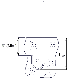
|
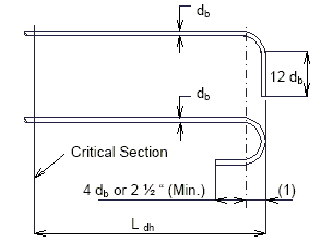
| |
| (1) = (#3 thru #8) | ||
| (1) = (#9, #10 and #11) | ||
| (1) = (#14 and #18) | ||
| DETAILS NEAR FREE EDGE OR CONSTRUCTION JOINT |
HOOKED-BAR DETAILS FOR DEVELOPMENT OF STANDARD HOOKS |
|---|
751.40.8.4.2.6 Development of Uncoated Grade 40 Deformed Bars in Tension, (AASHTO 8.25)
| Bar | = 3 ksi | = 4 ksi | = 5 ksi | |||
|---|---|---|---|---|---|---|
| Top bar | Top bar | Top bar | ||||
| #3 | 12 | 12 | 12 | 12 | 12 | 12 |
| #4 | 12 | 12 | 12 | 12 | 12 | 12 |
| #5 | 12 | 14 | 12 | 14 | 12 | 14 |
| #6 | 13 | 19 | 12 | 17 | 12 | 17 |
| #7 | 18 | 25 | 16 | 22 | 14 | 20 |
| #8 | 23 | 33 | 20 | 28 | 18 | 25 |
| #9 | 30 | 41 | 26 | 36 | 23 | 32 |
| #10 | 38 | 52 | 33 | 45 | 29 | 41 |
| #11 | 46 | 64 | 40 | 56 | 36 | 50 |
| #14 | 63 | 87 | 54 | 76 | 49 | 68 |
| #18 | 81 | 113 | 70 | 98 | 63 | 88 |
| Bar | = 3 ksi | = 4 ksi | = 5 ksi | |||
|---|---|---|---|---|---|---|
| Top bar | Top bar | Top bar | ||||
| #3 | 12 | 12 | 12 | 12 | 12 | 12 |
| #4 | 12 | 12 | 12 | 12 | 12 | 12 |
| #5 | 12 | 12 | 12 | 12 | 12 | 12 |
| #6 | 12 | 15 | 12 | 14 | 12 | 14 |
| #7 | 15 | 20 | 13 | 18 | 12 | 16 |
| #8 | 19 | 26 | 16 | 23 | 15 | 20 |
| #9 | 24 | 33 | 21 | 29 | 19 | 26 |
| #10 | 30 | 42 | 26 | 36 | 23 | 33 |
| #11 | 37 | 52 | 32 | 45 | 29 | 40 |
| #14 | 50 | 70 | 44 | 61 | 39 | 54 |
| #18 | 65 | 90 | 56 | 78 | 50 | 70 |
751.40.8.4.2.7 Minimum lap length for uncoated Grade 40 tension lap splices, (AASHTO 8.32)
| Other than Top Bars | Top Bars | |||||||||||||||||
|---|---|---|---|---|---|---|---|---|---|---|---|---|---|---|---|---|---|---|
| = 3 ksi | = 4 ksi | = 5 ksi | = 3 ksi | = 4 ksi | = 5 ksi | |||||||||||||
| Bar | A | B | C | A | B | C | A | B | C | A | B | C | A | B | C | A | B | C |
| #3 | 12 | 12 | 12 | 12 | 12 | 12 | 12 | 12 | 12 | 12 | 16 | 21 | 12 | 16 | 21 | 12 | 16 | 21 |
| #4 | 12 | 12 | 14 | 12 | 12 | 14 | 12 | 12 | 14 | 12 | 16 | 21 | 12 | 16 | 21 | 12 | 16 | 21 |
| #5 | 12 | 13 | 17 | 12 | 13 | 17 | 12 | 13 | 17 | 14 | 19 | 24 | 14 | 19 | 24 | 14 | 19 | 24 |
| #6 | 13 | 17 | 22 | 12 | 16 | 21 | 12 | 16 | 21 | 19 | 24 | 31 | 17 | 22 | 29 | 17 | 22 | 29 |
| #7 | 18 | 23 | 30 | 16 | 20 | 26 | 14 | 19 | 24 | 25 | 32 | 42 | 22 | 28 | 37 | 20 | 26 | 34 |
| #8 | 23 | 30 | 40 | 20 | 26 | 34 | 18 | 24 | 31 | 33 | 42 | 55 | 28 | 37 | 48 | 25 | 33 | 43 |
| #9 | 30 | 38 | 50 | 26 | 33 | 43 | 23 | 30 | 39 | 41 | 54 | 70 | 36 | 47 | 61 | 32 | 42 | 54 |
| #10 | 38 | 49 | 63 | 33 | 42 | 55 | 29 | 38 | 49 | 52 | 68 | 89 | 45 | 59 | 77 | 41 | 53 | 69 |
| #11 | 46 | 60 | 78 | 40 | 52 | 68 | 36 | 46 | 61 | 64 | 84 | 109 | 56 | 72 | 95 | 50 | 65 | 85 |
| Other than Top Bars | Top Bars | |||||||||||||||||
|---|---|---|---|---|---|---|---|---|---|---|---|---|---|---|---|---|---|---|
| = 3 ksi | = 4 ksi | = 5 ksi | = 3 ksi | = 4 ksi | = 5 ksi | |||||||||||||
| Bar | A | B | C | A | B | C | A | B | C | A | B | C | A | B | C | A | B | C |
| #3 | 12 | 12 | 12 | 12 | 12 | 12 | 12 | 12 | 12 | 12 | 16 | 21 | 12 | 16 | 21 | 12 | 16 | 21 |
| #4 | 12 | 12 | 12 | 12 | 12 | 12 | 12 | 12 | 12 | 12 | 16 | 21 | 12 | 16 | 21 | 12 | 16 | 21 |
| #5 | 12 | 12 | 14 | 12 | 12 | 14 | 12 | 12 | 14 | 12 | 16 | 21 | 12 | 16 | 21 | 12 | 16 | 21 |
| #6 | 12 | 14 | 18 | 12 | 13 | 17 | 12 | 13 | 17 | 15 | 19 | 25 | 14 | 18 | 23 | 14 | 18 | 23 |
| #7 | 15 | 19 | 24 | 13 | 16 | 21 | 12 | 15 | 20 | 20 | 26 | 34 | 18 | 23 | 29 | 16 | 21 | 27 |
| #8 | 19 | 24 | 32 | 16 | 21 | 28 | 15 | 19 | 25 | 26 | 34 | 44 | 23 | 29 | 38 | 20 | 26 | 34 |
| #9 | 24 | 31 | 40 | 21 | 27 | 35 | 19 | 24 | 31 | 33 | 43 | 56 | 29 | 37 | 49 | 26 | 33 | 44 |
| #10 | 30 | 39 | 51 | 26 | 34 | 44 | 23 | 30 | 39 | 42 | 54 | 71 | 36 | 47 | 62 | 33 | 42 | 55 |
| #11 | 37 | 48 | 63 | 32 | 42 | 54 | 29 | 37 | 49 | 52 | 67 | 87 | 45 | 58 | 76 | 40 | 52 | 68 |
751.40.8.4.3 Miscellaneous
Negative Moment Steel over Intermediate Supports
Dimension negative moment steel over intermediate supports as shown.
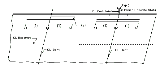
| Prestressed Structures: | |
|---|---|
| (1) | Bar length by design. |
| (2) | Reinforcement placed between longitudinal temperature reinforcing in top. |
Bar size: #5 bars at 7-1/2" cts. (Min.) #8 bars at 5" cts. (Max.)
| Steel Structures: | |
|---|---|
| (1) | Extend into positive moment region beyond "Anchor" Stud shear connectors at least 40 x bar diameter x 1.5 (Epoxy Coated Factor)(*) as shown below. (AASHTO 10.38.4.4 & AASHTO 8.25.2.3) |
| (2) | Use #6 bars at 5" cts. between longitudinal temperature reinforcing in top. |
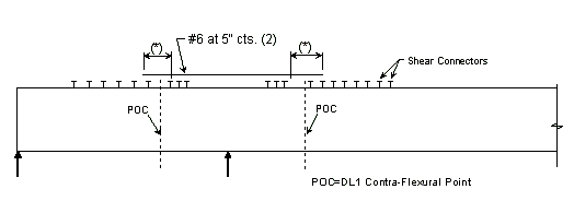
| (*) | 40 x bar diameter x 1.5 = 40 x 0.75" x 1.5 = 45” for #6 epoxy coated bar. |
751.40.8.5 General Superstructure
751.40.8.5.1 Concrete Slabs
751.40.8.5.1.1 Design Criteria
Slabs on Girders
Stresses:
= 1,600 psi = 4,000 psi = 8 = 60,000 psi
Moments Over Interior Support (Use for positive moment reinf. also) (Sec. 1.5 E40A)
| Dead Load = | (Continuous over 5 supports) | |
| Dead Load = | (Continuous over 4 supports) |
| Live Load = | Continuity Factor | = 0.8 | ||
| Impact Factor | = 1.3 | |||
| P | = 16 Kips for HS20 | |||
| P | = 20 Kips for HS20 Modified | |||
| Design Load: | ||||
Cantilever Moment
Dead Load = Moment due to slab, F.W.S. and S.B.C.
Live Load:
Wheel Load =
Where:
| = Wheel load (apply impact factor) | |
| = Distance from load to support (ft.) | |
| = |
Collision Load =
Where:
| = 10 kips (Collision force) | |
| = Moment arm (Curb ht.+ 1/2 Slab th.) | |
| = |
Where:
| = Distance from center of gravity of barrier to support |
Design of top reinforcement is based on maximum moment over supports or cantilever moment. Flexural reinforcement shall meet the criteria of AASHTO Art. 8.16.3.
When designing for bottom transverse reinforcement, a 1" wearing surface is removed from the effective depth.
Prestressed panels replace the bottom transverse reinforcement.
Prestressed panels are assumed to carry DL1 stresses. Therefore, the negative moment due to DL1 at interior supports may be neglected.
The maximum P/S panel width (clear span + 6") for HS20 Modified is 9'-6". (Based on 10'-0" girder spacing and 10" flanges) The maximum P/S panel width (clear span + 6") for HS20 is 9'-11".
Distribution of Flexural Reinforcement
Allowable Stress:
Where:
| = 130 k/in. | |
| = Dist. from extreme tension fiber to center of closest bar (concrete cover shalll not be taken greater than 2") | |
| = Effective tension area of concrete | |
| = | |
| = Bar spacing ctr. to ctr. |
Actual Stress:
Where:
| = Service load moment | |
| = Area of steel | |
| = | |
| = | |
| = | |
| = | |
| = Effective width | |
| = Effective depth |
Distribution of flexural reinforcement does not need to be checked in concrete considered unexposed to weather.
Longitudinal distribution reinforcement:
Top of slab - use #5 bars at 15" cts. for temperature distribution.
Bottom of slab - by design.
Negative moment reinforcement over supports:
Steel structures - add. #6 bars at 5" between #5 bars.
P/S girder structures - by design.
Additional reinforcement over supports shall be a minimum of #5 bars and a maximum of #8 bars at 5" ctrs. When necessary, replace the #5 temperature reinforcement with a larger bar to satisfy negative moment reinforcement requirement, but keep all bars within two bar sizes.
Note: See details of negative moment reinforcement.

| |
| CIP Slab | P\S Panel Slab |
|---|---|
| 3" Cl. preferred min., 2 3/4" Cl. preferred min. for P/S panels to accommodate #8 bars over supports and 2 1/2" Cl. absolute min. by AASHTO 8.22.1. |
Method of measurement:
The area of the concrete slab shall be measured and computed to the nearest square yard. This area shall be measured transversely from out to out of slab and longitudinally from end to end of bridge slab.
Precast Prestressed Panels
3" Precast prestressed concrete panels with 5-1/2" minimum cast-in-place concrete will be the standard slab used on all girder superstructures except curved steel structures.
Concrete for prestressed panels shall be Class A1 with = 6,000 psi, = 3,500 psi. Prestressing tendons shall be uncoated, low-relaxation, seven-wire(7) strands for prestressed concrete conforming to AASHTO M203 Grade 270, with nominal diameter of strand = 3/8" and area = 0.085 sq.in., minimum ultimate strength = 22.95 kips (270 ksi), and strand spacing = 4.5 inches.
Panels shall be set on joint filler or polystyrene bedding material. Filler thickness shall be a Min. of 3/4" and a Max. of 2". Standard filler width is 1 1/2" except at splice plates where 3/4" Min. is allowed to clear splice bolts. Joint filler thickness may be reduced to a minimum of 1/4" over splice plates on steel structures. For prestressed girder structures, joint filler thickness may be varied within these limits to offset girder camber or at the contractor's option a uniform 3/4" (Min.) thickness may be used throughout. The same thickness shall be used under any one edge of any panel and the maximum change in thickness between adjacent panels shall be 1/4 inch for steel spans and 1/2 inch for concrete spans.
Standard roadway cross sections and slab reinforcement for HS20 and HS20 Modified live loads are shown in this section. Reinforcement shown is for a cast-in-place slab or a P/S panel slab with the bottom layer of reinforcement between girders being replaced by the panels. Cantilever reinforcement details for P/S panel slab are shown in this section.
- Maximum panel width (clear span + 6") = 9'-6" for HS20 Modified.
- Maximum panel width (clear span + 6") = 9'-11" for HS20.
When a barrier or railing is permanently required on the structure, other than at the edge of slab, precast prestressed panels will not be allowed in the bay underneath the barrier or railing. Prestressed panels are not allowed for use as simply supported for live loads, i.e. staging, where only two supports may be provided for live loads.
S.I.P.
Stay-in-place corrugated metal forms with cast-in-place concrete may be used on horizontally curved steel structures with the approval of the Structural Project Manager.
The standard slab reinforcements shown in this section for HS20 live load were designed using S.I.P. Dead Loads. If design is for HS20 Modified, the standard slab reinforcement needs to be checked for S.I.P. forms.
The bottom transverse reinforcement shall maintain a 1" clear distance from the top of forms.
C.I.P.
8 1/2" cast-in-place concrete slab with conventional forming may be used at the contractor's option, on all girder structures. Conventional forming shall also be used between girders with stage construction joints.
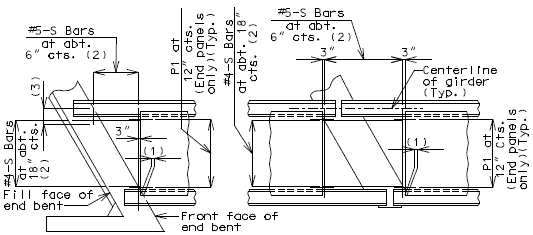
|
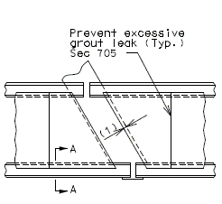
| |
| Panels-Squared Ends | Panels-Skewed Ends | |
|---|---|---|
| PLAN OF PRECAST PRESTRESSED PANELS PLACEMENT | ||
751.40.8.5.1.2 Details of Concrete Slabs for Structures
751.40.8.5.2 Timber Floor
| Maximum stringer spacing as determined by strength of timber floor | ||
|---|---|---|
| Stress = 1,200 lbs. per square inch | ||
| H-10 | H-15 | |
| (*) 3" x 12" Plank | 18" + 1/2 Flange Width | 16" + 1/2 Flange Width |
| 4" Laminated Floor | 2'-11" + 1/2 Flange Width | 2'-3" + 1/2 Flange Width |
| 6" Laminated Floor | 6'-0" + 1/2 Flange Width | 4'-4" + 1/2 Flange Width |
| Stress = 1,600 lbs. per square inch | ||
| H-10 | H-15 | |
| 3" x 12" Plank | 23" + 1/2 Flange Width | 21" + 1/2 Flange Width |
| 4" Laminated Floor | 3'-9" + 1/2 Flange Width | 2'-11 1/2" + 1/2 Flange Width |
| 6" Laminated Floor | 7'-10 3/4" + 1/2 Flange Width | 5'-9" + 1/2 Flange Width |
751.40.8.5.3 Steel Grid Bridge Flooring
In general, the 5" depth (concrete filled to half depth) steel grid bridge flooring shall be specified. Bar spacing may vary as necessary to meet minimum section modulus requirements. Main member spacing shall not exceed 10" and cross bar spacing shall not exceed 4". At present, the manufacturers of the following types have provided data to show they are acceptable:
- Greulich 5" Standard
- Foster 5" Standard
The section properties and maximum span for HS20 loading have been computed for these types and are as follows:
| Company | (For Design Purpose only) Weight (PSF) (Steel & Conc.) |
Main bar Spacing |
Cross bar Spacing |
Moment of Inertia | ||
| Mid Span | Over-Support | |||||
| Conc. | Steel | Steel | ||||
| Greulich | 48.0 | 7 1/2" | 3 3/4" | 99.41 | 12.43 | 9.03 |
| Foster | 48.0 | 8" | 4" | 128.1 | 16.01 | 12.25 |
| Company | Section Modulus | Maximum Span (*) | ||||||
| Mid-Span | Over-Support | Simple Span | Continuous Spans | |||||
| Conc. (Top) |
Steel (Bott.) |
Steel (Top) |
Steel (Bott.) |
ASTM A709 Gr. 36 |
ASTM A709 Gr. 50W |
ASTM A709 Gr. 36 |
ASTM A709 Gr. 50W | |
| Greulich | 59.5 | 3.53 | 3.90 | 3.14 | 4'-4" | 5'-10" | 5'-10" | 7'-1" |
| Foster | 72.5 | 4.68 | 5.25 | 4.30 | 5'-9" | 7'-5" | 7'-2" | 9'-4" |
The cross-section DETAILS used in computing the section properties are shown on the sketches on the following sheets. Maximum span determination included an allowance for a 35#/sq.ft. future
wearing surface and assumed a wheel load to be distributed, normal to the main bars, over a width of 4'-0".
(Place the following note on the Bridge Plans with the Steel Grid Details.
Note: The steel grid deck shall be electrically grounded.
(*) For main beams of grid either parallel or perpendicular to traffic.
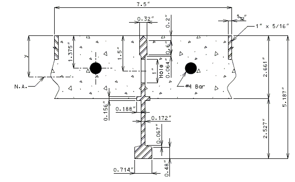
| Composite Section | Steel Section Only (net) | |
| y | 1.671" | 2.317" |
| Note: | Dimensions obtained form Greulich plans. |
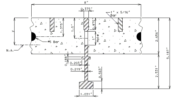
| Composite Section | Steel Section Only (net) | |
| y | 1.766" | 2.338" |
| Note: | Dimensions obtained form Foster Catalog. |
751.40.8.5.4 Longitudinal Diagrams
751.40.8.5.4.1 Hinged Beam Connections
The diagrams of various joints in steel structures are intended to be guides primarily for the determination of horizontal longitudinal dimensions for the plan view on the first sheet of plans.
These diagrams are not to be detailed on the design plans. However, the arrangement of the joints should be useful in detailing the longitudinal diagram for structural steel, particularly for bridges on grades and vertical curves.
Longitudinal dimensions for the plan of structural steel and for the plan of slab shall be horizontal from centerline bearing to centerline bearing.
For proper correlation of details when developing plans for widening or redecking bridges, match the method of dimensioning on the new plans with the method used on the originals.
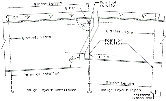
|
| Geometrics for Hanger Beam Connections for Bridges on Crown Vertical Curves |
|---|
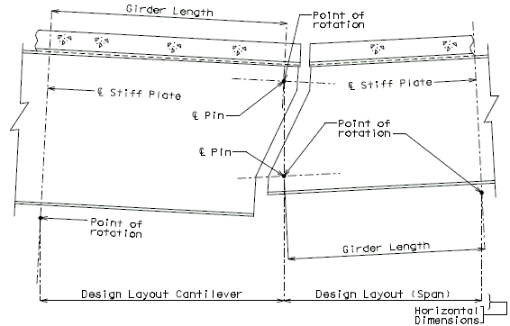
|
| Geometrics for Hanger Beam Connections for Bridges on Sag Vertical Curves |
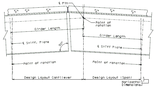
|
| Geometrics for Pin Plate Connections for Bridges on Crown Vertical Curves |
|---|
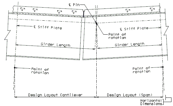
|
| Geometrics for Pin Plate Connections for Bridges on Sag Vertical Curves |
751.40.8.5.4.2 Longitudinal Sections
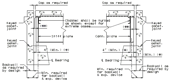
| |
| Bearing Stiffener | Connection Plate |
|---|---|
| Structures Not on Grade (Typical) | |
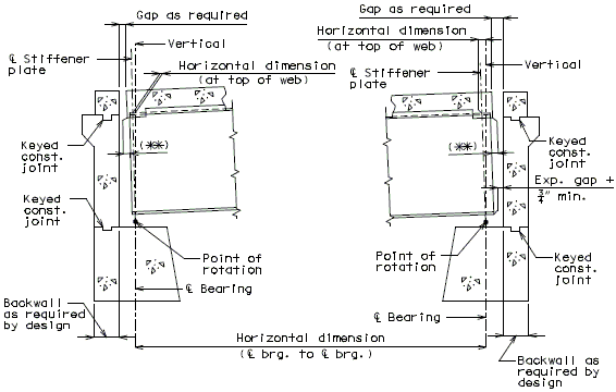
| |
| Structures on Grade (Typical) | |
| (*) | Parallel to Girder. All other dimensions shown are normal to backwall. |
| (**) | See EPG 751.13 Expansion Devices for dimension of overhang from end of stringer or girder to face of plate, edge of concrete or face of vertical leg of angle. |
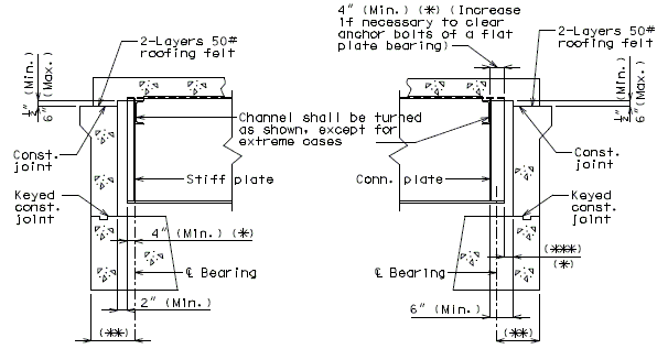
| |
| Bearing Stiffener | Connection Plate |
|---|---|
| Structures Not on Grade (Typical) | |
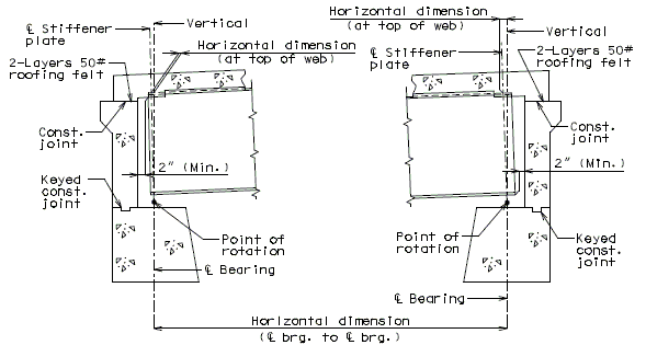
| |
| Structures on Grade (Typical) | |
| (*) | Parallel to Girder. All other dimensions shown are normal to backwall. |
| (**) | 18" min. (Use same dimension as the expansion device end on 3-span continuous, if it is not more than 2" greater.) |
| (***) | 3" min. for type C, D and E bearing, and 2" min. for an elastomeric bearing. |
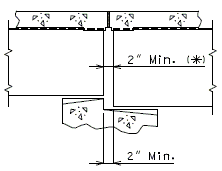
|
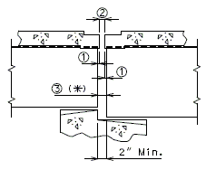
|
| No Expansion Device | Expansion Device |
|---|
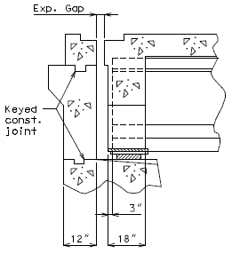
|
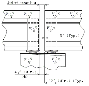
|
| Structures Not on Grade (Typical) | |
|---|---|
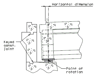
| |
| Structures On Grade (Typical) | |
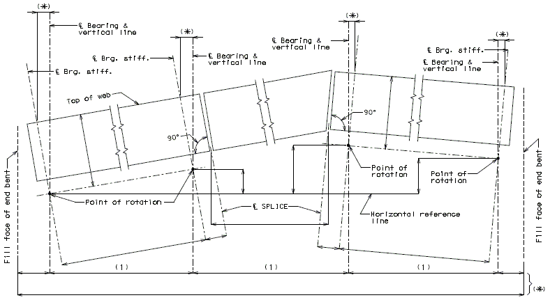
|
| Elevation of Longitudinal Steel Diagram |
|---|
| Note: | The typical elevation shown above should be detailed on the plans for all steel structures that are on vertical curve grades. |
| (1) | Longitudinal dimensions are horizontal from centerline Brg. to centerline Brg. |
| (*) | Horizontal dimensions. |
| BLOCKING DIAGRAM SHOULD NOT BE USED FOR CAMBERED GIRDERS. | |
|---|---|
751.40.8.5.5 Miscellaneous Bearing Connections
751.40.8.5.5.1 Typical Details of “Hinged Connection"
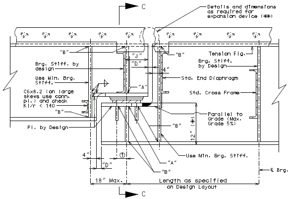
| ||||||||||||||||
| Section Showing Hinged Beam Connection | ||||||||||||||||
|---|---|---|---|---|---|---|---|---|---|---|---|---|---|---|---|---|
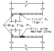
|

|
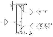
| ||||||||||||||
| Plan of Brg. Plate | ||||||||||||||||
| Detail of Web at Radius Transition |
Typical Welding Details for Stiff. Plates | |||||||||||||||
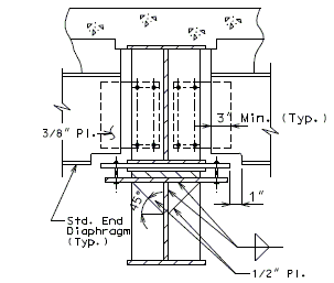
|
| |||||||||||||||
| Section C-C | ||||||||||||||||
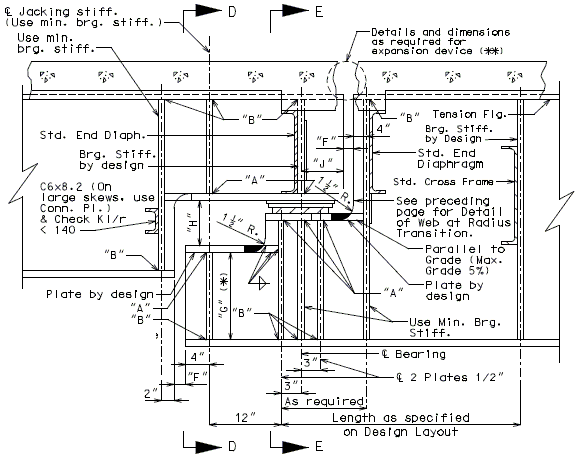
| |||
| Section Showing Hinged Beam Connection | |||
|---|---|---|---|
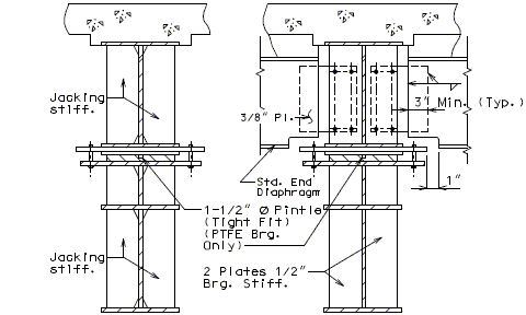
| |||
| Section D-D | Section E-E | ||
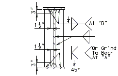
| |||
| Typical Welding Details for Stiff. Plates | |||
| (*) | See below for dimension "G". |
| (**) | See EPG 751.13 Expansion Devices |
| "F" | = Gap as required for expansion (3" Min.). |
| "H" | = 10 3/4" Min. (12" preferred.) |
| "J" | = 5" for bearing with 3" web thickness. Use 6" for all others. |
| All dimensions shown are minimum, increase, as necessary. | |
| Web Thickness |
Depth "G" |
(*) Allowable Dead Load Reactions, Kips (At 150% Overstress) |
Web Thickness |
Depth "G" |
(*) Allowable Dead Load Reactions, Kips (At 150% Overstress) | |
|---|---|---|---|---|---|---|
| 5/16" | 8" | 45.0 | 7/16" | 8" | 63.0 | |
| 5/16" | 9" | 50.6 | 7/16" | 9" | 70.8 | |
| 5/16" | 10" | 56.2 | 7/16" | 10" | 78.7 | |
| 5/16" | 11" | 61.8 | 7/16" | 11" | 86.6 | |
| 5/16" | 12" | 67.5 | 7/16" | 12" | 94.5 | |
| 5/16" | 13" | 73.1 | 7/16" | 13" | 102.3 | |
| 5/16" | 14" | 78.8 | 7/16" | 14" | 110.2 | |
| 5/16" | 15" | 84.3 | 7/16" | 15" | 118.1 |
| 3/8" | 8" | 54.0 | 1/2" | 8" | 72.0 | |
| 3/8" | 9" | 60.7 | 1/2" | 9" | 81.0 | |
| 3/8" | 10" | 67.5 | 1/2" | 10" | 90.0 | |
| 3/8" | 11" | 74.2 | 1/2" | 11" | 99.0 | |
| 3/8" | 12" | 81.0 | 1/2" | 12" | 108.0 | |
| 3/8" | 13" | 87.7 | 1/2" | 13" | 117.0 | |
| 3/8" | 14" | 94.5 | 1/2" | 14" | 126.0 | |
| 3/8" | 15" | 101.2 | 1/2" | 15" | 135.0 |
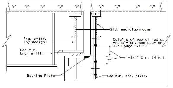
|
| Section Showing Hinged Beam Connection |
|---|
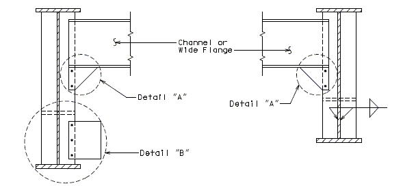
| |
| Plate Girder 42" Thru 46" Also 48" and Over |
Plate Girder 36" Thru 40" |
|---|---|
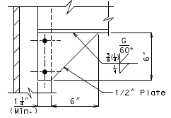
|
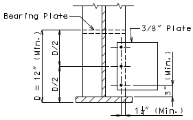
|
| Detail "A" | Detail "B" |
|---|
| Note: | Modify standard end diaphragm connections as shown above, if clearance problems exist between bearing plate and end diaphragm connection bolts. |
751.40.8.6 Composite Design
751.40.8.6.1 General
GENERAL
This portion of the article pertains to structures composed of steel girders with concrete slab connected by shear connectors. The stresses of composite girders and slab shall be computed based on the composite cross-section properties and shall be consistent with the properties of the various materials used. The regions subjected to positive moment are considered as composite and the regions subjected to negative moment are considered as non-composite. For the initial girder design, composite/non-composite regions can be approximately assumed as:
SECTION PROPERTIES
Cross-section properties of the composite section shall include concrete slab and steel section.
Cross-section properties of the non-composite section shall include steel section only.
Use composite property for positive moment section.
Use non-composite property for negative moment section. The effect of reinforcing steel in the section is not considered.
The ratio of modulus of elasticity of steel to that of concrete, n, shall be assumed to be eight. The effect of creep shall be considered in the design of composite girders which have dead loads acting on the composite section. In such structures, n=24 shall be used.
DESIGN UNIT STRESSES (also see note A1.1 in EPG 751.50 Standard Detailing Notes)
Reinforcement Concrete
| Reinforcing Steel (Grade 60) | = 24,000 psi | = 60,000 psi |
| Class B-2 Concrete (Substructure) | = 1,600 psi | = 4,000 psi |
Structural Steel
| Structural Carbon Steel (ASTM A709 Grade 36) | = 20,000 psi | = 36,000 psi |
| Structural Steel (ASTM A709 Grade 50) | = 27,000 psi | = 50,000 psi |
| Structural Steel (ASTM A709 Grade 50W) | = 27,000 psi | = 50,000 psi |
751.40.8.6.2 Design
751.40.8.6.2.1 Shear Connector Design
The shear connectors shall be designed for fatigue and checked for ultimate strength (AASHTO Article 10.38.5.1).
Step 1:
Compute Vr, the range of shear in kips, from the structural analysis, due to live loads and impact, for entire span.
At any section, the range of shear shall be taken as the difference in the minimum and maximum shear envelopes (excluding dead loads).
Step 2:
Use the average Vr per span, for the section of the span that is assumed to act compositely (from end of span to point of contraflexure for end spans, or from point of contraflexure to point of contraflexure for int. spans).
Step 3:
Using the average Vr from step 2, compute the range of horizontal shear load per linear inch, Sr in kips per inch, at the junction of the slab and stringer from the following equation:
(AASHTO Article 10.38.5.1.1 Eq. 10-58)
where:
= static moment of the transformed compressive concrete area about the neutral axis of the composite section, in cubic inches (*);
= moment of inertia of the transformed composite girder in positive moment regions in inches to the fourth power (*).
(*) In the formula, the compressive concrete area is transformed into an equivalent area of steel by dividing the effective concrete flange width by the modular ratio n=8.
Step 4:
Compute the allowable range of horizontal shear, Zr, in pounds on an individual connector, welded stud, by use of the following formula:
where:
=height of stud in inches;
=diameter of stud in inches;
=13,000 for 100,000 cycles
- 10,600 for 500,000 cycles
- 7,850 for 2,000,000 cycles
- 5,500 for over 2,000,000 cycles.
Step 5:
Compute the number of additional connectors required at point of contraflexure, N , from the following formula:
Pitch =
Where: Pitch = required pitch, in inches;
= the resistance of all connectors at one (1) transverse girder cross-section as a shear connector unit.
Note:
The pitch is to be constant and spaced in the composite section (round to the nearest inch).
Step 6:
Compute the required pitch of the shear connector units, pitch by the following formula:
(AASHTO Article 10.38.5.1.1 Eq. 10-69)
where:
= number of additional connectors required at the point of contraflexure;
= total area of longitudinal slab reinforcing steel for each girder over interior support;
= range of stress due to live load plus impact, in the slab reinforcement over the support (in lieu of more accurate computations, f may be taken as equal to 10,000 psi);
= the allowable range of horizontal shear on an individual connector.
This number of additional connectors, N , shall be placed adjacent to the point of dead load contraflexure within a distance equal to 1/3 of the effective slab width, if it is possible. If it is impossible, use minimum pitch of 6".
Step 7: Check connectors for ultimate strength
The number of connectors provided for fatigue must be checked to ensure that adequate connectors are provided for ultimate strength.
To check for ultimate strength, proceed as follows:
(1) Compute the force in the slab (P), which is defined as: at the point of maximum positive moment, the force in the slab is taken as the smaller value of the following two formulae:
(AASHTO Article 10.38.5.1.2 Eq. 10-62)
or
(AASHTO Article 10.38.5.1.2 Eq. 10-63)
Where:
= total area of the steel section including cover plates (if used);
= specified minimum yield point of the steel being used;
= compressive strength of concrete at age of 28 days;
= effective flange width given in AASHTO Article 10.38.3;
= thickness of concrete slab.
Note:
If it becomes impractical to place the number of shear connectors required by ultimate strength in the specified distance (structures with span ratios greater than 1.5); base the number and spacing of shear connectors on the fatigue analysis only.
Increase the haunch by 1/2"± more than what is required to make one size shear connector work for C.I.P. or S.I.P. option.
751.40.8.6.2.2 Shear Connector Spacing
If it becomes impractical to place the number of shear connectors required by ultimate strength in the specified distance (structures with span ratios greater than 1.5); base the number and spacing of shear connectors on the fatigue analysis only.
For a typical 3-spans bridge, the shear connector units can be approximately arranged as below:
751.40.8.6.3 Details
751.40.8.6.3.1 Shear Connector Details
Use precast prestressed panels on all tangent steel structures. Evaluate the viability of the use of P/S panels on curved structures on a case by case basis and use or include as an option to a CIP slab where deemed appropriate.
Whenever panels are used, the minimum top flange width shall be 12" for Plate Girders and 10" for Wide Flange Beams.
Steel girders shall be cambered when using P/S Panels. Minimum joint filler thickness is 3/4", except over splice plates, in which case use 1/4" minimum. Maximum joint filler thickness is 2".
Shear connectors shall have a minimum height equal to the top of panel.
Shear connectors shall be spaced by units and shear connectors in each unit shall be placed along of girder. On wide flange widths, two lines of connectors may be used if spacings and clearances allow.
Additional shear connectors, Nc, at point of contraflexure may be placed in units normal to girder as space allows or in a single row along girder as shown below:
P/S strands shall extend 3" minimum and 6" maximum past edge of precast prestressed panel and not closer than 1" to the adjacent panels.
Panel end at splices shall be notched to avoid bolt heads as shown below:
![]() 3/4" min. wide bearing edge for panel at splice, typ. (*)
3/4" min. wide bearing edge for panel at splice, typ. (*)
![]() 4 x (Stud diameter) preferred minimum, may be reduced if necessary for a more economical design; 2-1/4" absolute minimum.
4 x (Stud diameter) preferred minimum, may be reduced if necessary for a more economical design; 2-1/4" absolute minimum.
(*) In order to meet ![]() and
and ![]() above, it is necessary to have an edge bolt distance of 2" or greater for splice plate. For unusual cases, which would require field splices for flange widths 14" or 15" for P/S precast panel option, it will be necessary to change the top flange width to either 13" or 16" of equal area to maintain the 3/4" minimum panel bearing edge on the splice plates.
above, it is necessary to have an edge bolt distance of 2" or greater for splice plate. For unusual cases, which would require field splices for flange widths 14" or 15" for P/S precast panel option, it will be necessary to change the top flange width to either 13" or 16" of equal area to maintain the 3/4" minimum panel bearing edge on the splice plates.
Minimum joint filler thickness is 3/4" except over splice plates in which case use 1/4" minimum. When joint filler is less than 1/2" thick over splice plate, make the width of joint filler at splice the same width as panel on splice (maximum 1-1/2" wide).
Maximum difference in top of flange thickness should be checked so that joint filler thickness does not exceed 2".
751.40.8.6.3.2 Deflection
Allowable Live Load Deflection
| 1. | Composite Design: | Defl. | = 1/1000 of span; |
| 2. | Non-composite Design: | Defl. | = 1/800 of span |
- Where:
- Defl. = allowable deflection due to service live load plus impact.
Dead Load Deflection
Compute at 1/4 point for bridge with spans less than 75’, at 1/10 points for spans 75’ and over.
751.40.8.7 Wide Flange Beam Spans
751.40.8.7.1 Design
751.40.8.7.1.1 Design Data
Slabs
| Reinforcing Steel | = 60,000 psi | ||||
| Concrete | = 1,600 psi | = 4,000 psi | |||
| = 8 |
Simple Design Span
Design Span = Center to Center of Bearings.
Dead Load
Live Load Distribution Factors
See EPG 751.40.8.2.2 Distribution of Live Load
Live Load Deflection Allowable
| Composite | |
| Non-Composite |
Live Load Reaction
Live Load Wheel Line is the Live Load Reaction per Wheel Line, no distribution, no impact; Maximim Live Load Impact is the Live Load Reaction x Distribution Factor = Impact.

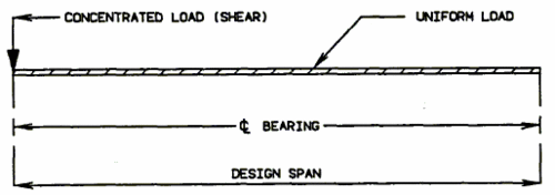
Typical Continuous Steel Structures - Integral End Bents:

751.40.8.7.1.2 Stringer Design
Stresses:
| Steel: | AASHTO - Article 10.2, 10.32 | ||
| ASTM A709 Grade 36 | = 36,000 psi | ( = 20,000 psi) | |
| ASTM A709 Grade 50 & Grade 50W | = 50,000 psi | ( = 27,000 psi) | |
| Superstructure Concrete: | = 1,600 psi | |
| = 4,000 psi | ||
| = 8 |
| Reinforcing Steel: | = 60,000 psi |
Physical Properties of Spans
- Composite Design - See Widening and Repair - Composite Design.
- Non-Composite Design - Use "Constant I" analysis.
When the neutral axis of a composite section falls in the concrete fange, the section shall be designed as Non-Composite (21" Wide Flange is the smallest beam generaly made conposite).
Deflection
Live Load Deflection: AASHTO - Article 10.6 Composite - Allowable Deflection L/1000 Non-Composite - Allowable Deflection l/800 Dead Load Deflection: Compute at 1/4 points for bridges with spans less than 75', at 1/10 points for spans 75' and over. Give percentage of deflection due to weight of structural steel.
Fatigue Stress
AASHTO - Article 10.3 Case I, Case II or Case III (as specified on Bridge Memorandum generally within the following limitations).
Case I: Bridges with the TRUCK traffic count of 2500 or more vehicles per day (one direction). Case II: Bridges with traffic count of 750 or more vehicles per day, and less than 2500 TRUCK traffic count (one direction) per day. Case III: Bridges with traffic count of less than 750 vehicles per day, except when Live Loading is H20 or greater. No Fatigue: Bridges with traffic of less than 75 vehicles per day.
Economic Comparison
When comparing cost of low-alloy steels (A-572, Gr.-50, and A-588) to the cost of A-36 steel, the low-alloy steels shall be figured a t 3 1/2 cents for A-572, Gr.-50 and 5 1/4 cents for A-588 per pound more than A-36 steel. Cost comparisions will be based on current average bid prices that may be obtained from the CHIEF DESIGNER, for comparable bridges.
No overstressed will be permitted in the design.
Total Capacity of Exterior Griders (Dead Load and Live Load)
In no case shall an exterior stringer have less carrying capacity than an interior stringer.
751.40.8.7.1.3 Flange Plate Lengths
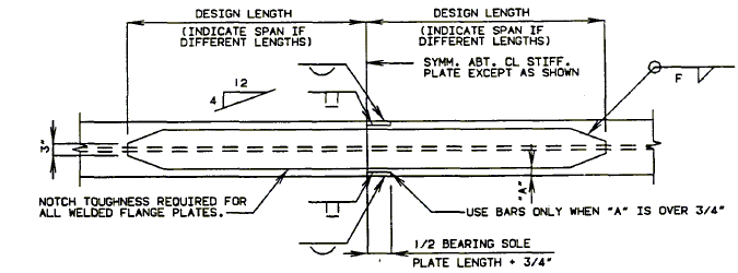
| |
| Top Flange | Bottom Flange |
|---|---|
| Details of Flange Plates at Intermediate Bents | |
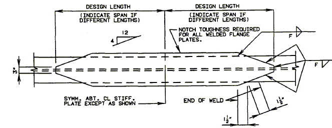
| |
| Details of Flange Plates at Intermediate Bents (Top and Bottom Flanges) | |
Allowable flange plate sizes are as shown with the section properties. Different plate sizes may be used on adjacent stringers.
Lengths to be shown on the bridge plans are those required as follows:
- Lengths each side of the bearing shall be the larger of:
- Theoretical End + Terminal Distance (***) or
- Point where the stress range (tension or reversal) in the beam flange is equal to or less than allowable fatigue stess range (Cat. E or E') or where the beam flange is in compression, whichever is smaller.
- Use Cat. E when the flange is less than or equal to 0.8 inch thick.
- Use Cat. E' when the flange is greater than 0.8 inch thick.
(***) Where the theoretical end = the point where the flange stress without cover plate less than or equal to base allowable stress. Terminal distance = 1 1/2 times nominal cover plate width.
The total length of the cover plate greater than or equal to (2D + 3'-0"). Where "D" = Depth of beam in feet.
When required lengths of plates vary by 12" or less on adjacent stringers or on each side of the centerline stiffener plate, use greater length for all such positions.
Plate lengths taken form the computer programs should be rouned up to at least the nearest 6".
751.40.8.8 Welded Plate Girders
751.40.8.8.1 Design
751.40.8.8.1.1 Design Assumptions & Procedures
Design Unit Stresses
| Reinforcement Concrete | ||
| Reinforcing Steel (Grade 60) | = 24,000 psi, | = 60,000 psi |
| Class B2 Concrete (Superstructure) | = 1,600 psi, | = 4,000 psi |
| Structural Steel: | ||
| Structural Carbon Steel (ASTM A709 Grade 36) | = 20,000 psi, | = 36,000 psi |
| Structural Steel (ASTM A709 Grade 50) | = 27,000 psi, | = 50,000 psi |
| Structural Steel (ASTM A709 Grade 50W) | = 27,000 psi, | = 50,000 psi |
Design Procedure:
Moments and shears by "Variable I" analysis:
- use computer program.
Trial sections from "Preliminary analysis":
- Combination of web depth, flanges and length of plates used shall be the most economical section available with depths compatible with vertical clearance requirements. Web depths in 6" increments are preferred, however other increments may be used when required by the Bridge Memorandum. (See Structural Project Manager)
Flanges:
Minimum flange dimensions = 3/4" x 12" (*).
Increments:
- Thickness 1/8"
- Width 1"
Maximum flange dimensions:
- Reference AASHTO - Table 10.32.1A)
- maximum thickness = 4"
Note: It is preferred office practice to maintain the same flange thickness at as many locations as practical. This can be accomplished by varying the flange width.
(*) For shipping and erection purposes, minimum width of both compression and tension flanges shall not be less than L/85 where L is the shipping length of the girder. This limitation is for preventing out-of-plane distortion of the girder.
Webs:
Web dimensions:
- (Reference AASHTO - Article 10.34 & 10.48)
- ASTM A709 Grade 36 = 3/8" minimum thickness for curved girders and for continuous straight girders.
- ASTM A709 Grade 50W = 3/8" minimum thickness.
- AASHTO - Article 10.3 Case I, Case II or Case III.
- Case I
- Bridges with the truck traffic count of 2500 or more vehicles per day. (One direction)
- Case II
- Bridges with traffic count of 750 or more vehicles per day, and less than 2500 truck traffic count (One direction) per day.
- Case III
- Bridges with traffic count of less than 750 vehicles per day, except when live loading is H20 or greater.
- No Fatigue:
- Bridges with traffic count of less than 75 vehicles per day.
Total Capacity of Exterior Girders:
(Dead Load and Live Load)
- In no case shall an exterior girder have less carrying capacity than an interior girder.
Horizontal Curved Girders Design Procedures (*)
Curved plate girders are to be designed using load factor design criteria. The 1980 AASHTO Guide Specifications for Horizontally Curved Highway Bridges as revised by Interim Specifications for Bridges 1981, 1982, 1984, 1985 and 1986 is to be applied with the USS Highway Structure Design Handbook (\) V-Load method to be used as a working example.
The following procedure may be followed to determine the required cross-section for any system of curved girders with skews less than 46°.
1. Determine the primary moments by the same procedures as for a system of straight girders, using the developed lengths of the curved girders.
2. From primary moments, compute shear loads, , using the formula:
| = Shear loads. M = Primary moments. | |
| = Radius of curvature (outside girder). = Radial distance between inside and outside girders. = Distance between diaphragms measured along axis of outside girder. |
The following coefficients may be applied to "" for the various multiple-girder systems with equal spacing between girders.
| SYSTEM | COEFFICIENT FRACTION |
COEFFICIENT DECIMAL |
| 2 girders | 1 | 1.00 |
| 3 girders | 1 | 1.00 |
| 4 girders | 10/9 | 1.11 |
| 5 girders | 5/4 | 1.25 |
| 6 girders | 7/5 | 1.40 |
| 7 girders | 14/9 | 1.56 |
| 8 girders | 12/7 | 1.72 |
| 9 girders | 15/8 | 1.88 |
| 10 girders | 165/81 | 2.04 |
3. Compute moments
- Reference: USS "Highway Structures Design Handbook" 1965 Edition. (Updated 1986 Volume II Section 6) developed by Richardson, Gordon and Associates in cooperation with Dr. John Scalzi is to be used as a working example.
4. Compute lateral bending moments using the approximate formula:
| = Lateral bending moment | ||
| = The values are approximately equal to the reactions at the supports. | ||
| = Depth of girder between centers of gravity of flanges. | ||
| = Primary moment + Secondary moment. |
5. Determine cross-section required to provide for vertical and lateral forces computed under Items 1 to 4 inclusive. As with any statically indeterminate system it is necessary to make an initial assumption of the required cross-sections and to repeat the calculations one or more times to obtain reasonable agreement between the assumed and required sections.
6. The non-compact section requirement that is to be applied to all sections with the tension flange and the compression flange as to ensure conservative design.
In computing , use to be actual diaphragm spacing for compression and tension stresses.
The value of is to be selected as plus or minus in the equations for to give the worst possible case.
Design and Detail Guides
1. Economic Arrangement of Spans and Depth-to-Spans Ratios
Where there is flexibility in span arrangement, the same guides that apply to economic arrangement of straight girders are equally applicable to curved girders. Similarly the rules used to establish depth-to-span ratios for straight girders usually will apply to curved girders.
2. Spacing of Girders
Spacing depends on the arrangements of diaphragms and bracing. In general, however, it will be found that the most economical arrangement for straight girders will accord very well with the best arrangement for a system of curved girders. The effect of curvature increases in proportion to the square of the span length and decreases in proportion to the radius of curvature and the spacing of girders.
3. Arrangement and Spacing of Diaphragms
The diaphragms shall be placed radially, with a maximum spacing of 15'-0". In order to minimize lateral bending of the girder flanges, the flanges should be as wide as practical.
Sway frame bracing is selected for curved girder system, by same methods as for straight girders.
4. Effect of Lateral Bracing
made in a similar manner as for straight bridges. If lateral Provision for lateral loading on curved girders may be bracing is used in a system of curved girders, the forces resulting from the radial components of flange stress may be carried partially or entirely by the bracing system; when both diaphragms and lateral bracing are used, radial reaction components may be divided between the two systems.
5. Approximate Estimate of Curvature
The following formula may be used in making preliminary approximations of the effect of curvature:
| Note: For "r" refer to paragraph No. 7 | |
| (*) |
| (*) | May be omiteed if supports are on radial lines. |
| % increase in positive moment due to effect of curvature. | |
| Radius of inside girder. | |
| Radius of outside girder. | |
| Distance between points of contraflexure in any pisitive moment area. | |
| Spacing between inside and outside girders. |
In the above form, the formula applies to a two-girder system, but it may be modified by reference to the table of coefficients for multiple-girder systems shown in Item #2. From primary moments, compute shear loads.
The formula applies particularly to positive moment, but for preliminary approximation it may be assumed that the curvature effect on negative moments will be about the same.
6. Design of Diaphragms and Connections
Where the degree of curvature is equal to or under 1° - 30' and when spans are equal to or under 75'-0" in length, the diaphragm and connections shall be the same as for Bridges with straight girders. Where the degree of curvature is over 1°- 30' to 3° or with a span length of more than 75'-0", the diaphragm must be attached to the tension flange. Where the degree of curvature is over 3°, a special design will be required for connection of intermediate diaphragms to flanges.
The maximum allowable diaphragm spacing is 15'-0", regardless of the amount of curvature, or span lengths.
The following applies to those bridges where the special design is to be considered:
Since diaphragm moments due to effect of curvature are a function of the radial component of flange stress, they are directly proportional to the vertical bending moment in the girders.
For exterior girders the moment in the diaphragm equals , in which = vertical bending moment in girder for any particular condition of loading; = diaphragm spacing; = Radius of curvature of girder.
For negative moment over the support, the value used in this equation should be the average moment between a point at the support and a point at the first adjacent diaphragm.
Diaphragm connections may be made directly to the flanges of the girders or through stiffeners, provided details are arranged to adequately transfer radial components of flange stress into the diaphragms.
7. Supports positioned other than on radial lines.
If field conditions permit, the most orderly arrangement for curved girders will be attained by placing the supports on radial lines.
It may be necessary to treat each line of girders independently, first finding the direct loading moments and then correcting for curvature by applying the separate .
8. Transverse stiffeners
The maximum transverse stiffener spacing for curved plate girders is , the web height.
Transverse stiffeners should be placed along the girder length only as far as required by design.
The maximum spacing of the first transverse stiffener at the simple support end of a curved plate girder is .
Reference:
- AASHTO - Article 10.5
- Limit radius of heat curved girders according to AASHTO Article 10.15.
Where the distance between field splices of curved girders exceeds that given by the following formula, a special note shall be placed on the plans.
| = | (*) | |
| = | Allowable distance between field splices, in feet. | |
| = | Allowable fs of flange steel, in psi. e.g. use 20,000 psi for Grade 36 steel. | |
| = | Weight of girder (flanges and web), in pounds per foot. | |
| = | Section Modulus of girder about x-x axis as shown, in inches cubed. |
Note:
If flanges are of different sizes, use smaller Section Modulus.
See Structural Project Manager for allowable overstress.
(*) Derivation
- Positive moment at centerline,
- Substitute mom. in fs equation.
- solve for L
Design Example
ASTM A709 Grade 36 Steel
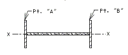
| |||||||||||
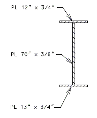 |
| ||||||||||
| SECTION A-A | |||||||||||
| Weight per Foot of Girder |
| PL 12" x 3/4" = 30.6 lbs./ft. |
| PL 70" x 3/8" = 89.3 lbs./ft. |
| PL 13" x 3/4" = 33.2 lbs./ft. |
| Total = 153.1 lbs./ft. |
From Formula:
(Use 57.5')
Special Note:
Heat curving of girders (Identify) (*) will not be allowed shile in the horizontal position.
(*)Complete underlined portion as required.
Maximum Plate Lengths:
- 80 feet. See Structural Project Manager for use of longer lengths up to 85' for ASTM A709 Grade 50 or ASTM A709 Grade 50W and 100' for ASTM A709 Grade 36.
Minimum Plate Lengths:
- 10 feet. Shop flange splices should be eliminated and extra plate material used when :economy indicates and span lengths permit.
Preliminary Analysis:
- (1) Compute moments from influence lines on basis of "Constant I" analysis and apply the following percentage increase or decrease to non-composite dead load moments.
References may be used in lieu of the above.
| = 1.2 to 1.5 | = 1.2 to 1.5 | ||||||||||||||
|
|
(2) Determine trial sections and plot a rough moment curve to determine location of flange plate cutoffs, if any.
(3) Complete analysis by using computer programs to obtain actual moments and stresses.
Design Stress investigation for Positive Moment Area of Plate Girder Structure
The design stresses are to be checked at the top of flange (steel) and the top of concrete slab in the composible area of Plate Girder Structures to ensure that they are within the allowable stresses.
SECTION A-A
Structure Length
Typical Continuous Steel Structures- Integral End Bents:
Estimated Girder Depth
Based on Three Spans With Ratio N = 1.3±
Continuous Plate Girders HS20 Loading Load Factor
(ASTM A709 Grade 50 or ASTM A709 Grade 50W)
| Initial Estimate (Feet) |
Girder Depths (*) (Inches) |
Structure Depth (**) (Feet) |
| 85 to 104 | 42 | 4.50 |
| 105 to 124 | 48 | 5.00 |
| 125 to 134 | 54 | 5.50 |
| 135 to 144 | 60 | 6.00 |
| 145 to 159 | 66 | 6.50 |
| 160 to 174 | 72 | 7.00 |
| 175 to 184 | 78 | 7.50 |
| 185 to 194 | 84 | 8.00 |
| 195 to 204 | 90 | 8.50 |
Trial steel plate girder depths use program BR109 to check designs and deflections. Web depths may be adjusted by two inch increments.
(*) Bethlehem steel economic study (N = 1.3±). Bethlehem steel provided an economic study of multiple steel girder depths. The study indicated that cheaper designs are obtained by reducing the plate girder depths and reducing the number of stiffeners. The recommended initial estimates above are based on these designs.
(**) Structure depth includes slab and haunch.
A general rule of thumb is to determine the minimum web thickness without stiffeners; then, use a web thickness of one-sixteenth inch less. Match MoDOT requirements for web increments of one-sixteenth inch only.
If two-span structures are used, a deeper web is required. A good estimate is to use six inches additional depth than the above tables for two-span structures.
751.40.8.8.2 Details
751.40.8.8.2.1 Field Flange Splice – Bolted
General
Splices shall be designed using the Service Load Design Method and in accordance with AASHTO Articles 10.18, 10.24 and 10.32 except as noted.
Splices shall be designed to develop 100% of the flange strength by the flange splice plate strength. When the flange section or steel grade changes at a splice, the smaller flange strength shall be used to design the splice. Splice plates shall then match the lower grade used in the flanges.
Minimum Yield Strength and Minimum Tensile Strength
| ASTM A709 Grade 36 | = 36 ksi | = 58 ksi |
| ASTM A709 Grade 50 | = 50 ksi | = 65 ksi |
| ASTM A709 Grade 50W | = 50 ksi | = 70 ksi |
Allowable Steel Stresses
Allowable stresses are determined by AASHTO Table 10.32.1A.
| Allowable tensile stress |
| ASTM A709 | Grade 36 | = 20 ksi |
| ASTM A709 | Grade 50 | = 27 ksi |
| ASTM A709 | Grade 50W | = 27 ksi |
Allowable Bolt Stresses
Splices shall be designed as slip critical connections with Class B surface preparation and oversized holes. Although standard holes are used in the fabrication of flange splices, designing the splices for oversize holes allows for some fabrication and erection tolerances. All splice bolts shall be 7/8" diameter ASTM F3125 Grade A325.
AASHTO Table 10.32.3C specifies = 19 ksi for a class B slip-critical connection. Tables shown in this article are based on 19 ksi that should also be used to design splices not listed in the table.
Although slip-critical connections are theoretically not subject to shear and bearing, they must be capable of resisting these stresses in the event of an overload that causes slip to occur. The allowable shear stress per bolt for bearing is 19 ksi with the threads included and ksi for threads not included.
Flange Strength
The flange strength shall be determined by multiplying the allowable stress of the flange by the area of the flange. The area of the flange shall be taken as the gross area of the flange, except that if more than 15 percent of each flange area is removed, that amount removed in excess of 15 percent shall be deducted from the gross area. Bolt holes are considered to be 1" diameter for the purpose of determining flange area.
Splice Plate Strength
The splice plate strength shall be determined by multiplying the allowable stress of the splice plates by the area of the splice plates. The area of the splice plates shall be taken as the gross area of the splice plates, except that if more than 15 percent of the splice plate area is removed, that amount in excess of 15 percent shall be deducted from the gross area.
Two Row Splices
Splices with two rows of bolts are used with flanges 12 to 13 inches wide. The inner and outer plates may either be the same length or the inner plate may be shorter. This is the case if the end bolts in the splice are only needed to be in single shear. All other bolts will be in double shear. (See Figure 3.42.2.2-1)
Figure 3.42.2.2-1
Four Row Splices
When the width of the flange being spliced is 14 inches or greater, four longitudinal rows of bolts are used. Three variations of the end bolts positioning may be used. In each of these variations, the last two bolts shall be located in the outer rows closest to the edge of the splice plate.
Figure 3.42.2.2-2
Flange Width Transitions
When the width of the flanges being spliced differs by more than 2", the larger flange shall be beveled as shown in Figure 3.42.2.2-3
Figure 3.42.2.2-3
Weight of Splice
When calculating the weight of splice, the following simplified weights shall be used.
Weight of High-Strength bolts (diameter 7/8") = 0.95 lbs/bolt
Unit weight of Structural Steel = 490 lbs/ft3
751.40.8.8.2.2 Field Web Splice – Bolted
General
Splices shall be designed using the Service Load Design Method and in accordance with AASHTO Articles 10.18, 10.24 and 10.32 except as noted.
The web splice consists of 2-Plates:
- Thickness = 5/16" minimum.
- Width = 12-1/2" (18-1/2" if 3 rows of bolts are required).
When the web section or steel grade changes at a splice, the smaller web strength should be used to design the splice.
Minimum Yield Strength and Minimum Tensile Strength
| ASTM A709 Grade 36 | = 36 ksi | = 58 ksi |
| ASTM A709 Grade 50 | = 50 ksi | = 65 ksi |
| ASTM A709 Grade 50W | = 50 ksi | = 70 ksi |
Allowable Steel Stresses
Allowable stresses are determined by AASHTO Table 10.32.1A.
| Allowable bending stress | |
| Allowable shear stress |
| ASTM A709 Grade 36 | = 20 ksi | = 12 ksi |
| ASTM A709 Grade 50 | = 27 ksi | = 17 ksi |
| ASTM A709 Grade 50W | = 27 ksi | = 17 ksi |
Allowable Bolt Stresses
Although standard holes are used in the fabrication of web splices, designing the splices for oversize holes allows for some fabrication and erection tolerances. Web splices required to resist shear between their connected parts are designated as slip-critical connections. Shear connections subjected to stress reversal, or where slippage would be undesirable, shall be slip-critical connections. Potential slip of joints should be investigated at intermediate load stages especially those joints located in composite regions. The resultant force shall be less than the allowable bolt shear force. All splice bolts shall be ASTM F3125 Grade A325 7/8" diameter High Strength Bolts.
= 19 ksi
Bolt Arrangement
The minimum distance from the center of any fastener in a standard hole to a sheared or thermally cut edge shall be 1-1/2 inches for 7/8" diameter fasteners. The minimum distance between centers of fasteners in standard holes shall be three times the diameter of the fastener, but shall not be less than 3 inches for 7/8" diameter fasteners.
Splice Plate Strength
The strength of the splice plates shall be determined by multiplying the allowable stress of the splice plates by the net area of all splice plates. The splice plates net area shall be taken as the gross area of the splice plates minus the bolt holes. Bolt holes are considered to be 1 inch diameter for the purpose of determining splice plate net area. Web splices are designed to develop 75% of net section of the web.
Web Strength
The strength of the web should be determined from the allowable web stress at the "top of web" to account for hybrid sections. Otherwise, the allowable web stress is based on a linear distribution of stress from outside face of flange to "top of web".
Weight of Splice
When calculating the weight of splice, the following simplified weights shall be used.
Weight of High-Strength bolts (diameter 7/8") = 0.95 lbs/bolt
Unit weight of Structural Steel = 490 lbs/ft3
751.40.8.9 Continuous Concrete Slab Bridges
751.40.8.9.1 Slabs
751.40.8.9.1.1 Design Assumptions
| Stresses - | FC | = | 1600 psi | N | = | 8 | (Slab, Integral Column) |
| FC | = | 1200 psi | N | = | 10 | (Open Bent, Footing) | |
| FY | = | 60,000 psi reinforcing steel | |||||
Use "Variable I" analysis for all structures except solid slabs without drop panels.
Use "Constant I" analysis for solid slabs without drop panels.
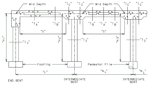
| "L" | = | Design Span |
| "H" | = | Design Height |
| "I" | = | Gross moment of inertia of the full cross-section (Slab minus voids - integral wearing surface not included) ("I1", "IA", etc. suggested I's to be considered.) |
| "S" | = | The effective span length for the use in determining minimum slab thickness under load factor design (AASHTO 8.9). |
Use the same column diameter and spacing for all Intermediate Bents.
Use the same slab thickness for all spans.
| DEGREE OF RESTRAINT - LONGITUDINAL | ||||
| Column Type | Footing Type | Top Column | Bottom Column | |
| INT. BENTS | Integral Column | Spread or Pile | Integral | (**) |
| Integral Column | Pedestal Pile | Integral | (**) | |
| END BENTS | Pinned Column | any | Pinned | (**) |
| Integral Pile | (*) Pinned | |||
| Open Bent with Column | any | Simple | ||
| INT. BENTS | Open Bent with Pile | Simple | ||
| (*) | See EPG 751.40.8.9.2.5 Design Assumptions for Integral Piles. | |
| (**) | Use "Pinned" for Seismic Performance Category A and "Fixed for Seismic Performance Categories B, C & D. (See Structural Project Manager or Liaison) |
751.40.8.9.1.2 Slab Design and Drop Panel
The Slab Depth is based on the following limitations:
| 1. | Vertical Clearance Requirements: see the Bridge Memorandum. | ||||
| 2. | Allowable Depths: | ||||
| A. | Positive Moments - | ||||
| see table of "Available Slab Depths and Void Data", in EPG 751.40.8.9.1.4 Slab Cross Section and Section Properties. | |||||
| B. | Slab Depth controlled by the minimum thickness formula - | ||||
| (Integral wearing surface is included with the total depth provided.) | |||||
| Continuous Spans - AASHTO 8.9 = (S + 10)/30 | |||||
| "S" | may be used as the clear distance between drop panels. | ||||
| Bridges may have two adjacent spans averaged if S2/S1 < 1.5 | |||||
| Simple Spans - AASHTO 8.9 = 1.2 (S + 10)/30 | |||||
| C. | Negative Moments - | ||||
| DROP PANEL DEPTHS | ||
| MIN. | MAX. | |
| Bents in median of dual roadway | 0" or 3" | 13" |
| Other Bents | 0" or 3" | 9" |
| INCREMENTS OF 1" | ||
| APPROXIMATE DROP PANEL WIDTH (FEET) (PARALLEL TO THE CENTERLINE OF ROADWAY) | |||||||
| Bents | Drop Panel Depth | ||||||
| 4" | 6" | 7" | 8" | 9" | 12" | ||
| 3 Span Bridge | 2 & 3 | 6' | 6' | 10' | 8' | 6' | |
| 4 Span Bridge | 2 & 4 | 6' | 6' | 10' | 8' | 6' | |
| 3 | 8' | 10' | 12' | 12' | 12' | 12' | |
| THESE WIDTHS ARE SUGGESTED ONLY AS TRIAL DIMENSIONS FOR DESIGN AND ARE NOT TO BE USED AS LIMITS FOR THE FINAL DESIGN. | |||||||
| 3. | Reinforcing Steel: | ||||
| A. | Positive Moments = Maximum #11 @ 5" cts. | ||||
| B. | Negative Moments = Maximum #11 @ 5" cts., except #14s @ 6" cts., may be used for long spans. | ||||
| 4. | Live Load Deflection - AASHTO 10.6 | ||||
| The deflection due to service live load plus impact shall not exceed 1/800 of the span, except on bridges in urban areas used in part by pedestrains whereon the ratio preferably shall not exceed 1/1000. | |||||
751.40.8.9.1.3 Slab Longitudinal Sections
HOLLOW SLABS

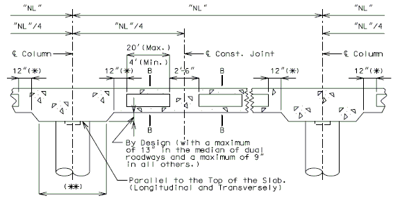
|
(*)Increase to maintain 6" minimum on skews (see detail) |
| (**) By Design (6" increments measured normal to the centerline of bent) (The minimum is equal to the column diameter + 2'-6") | |
| Note: All longitudinal dimensions shown are horizontal (Bridges on grades and vertical curves, included). For Sections A-A and B-B see EPG 751.40.8.9.1.4 Slab Cross Section and Section Properties. |
SOLID SLABS
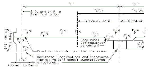
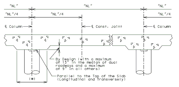
(*) By Design (6" increments measured normal to the centerline of Bent) (The minimum is equal to the column diameter + 2'-6")
Note:
All longitudinal dimensions shown are horizontal (Bridges on grades and vertical curves, included).
751.40.8.9.1.4 Slab Cross Section and Section Properties

| HALF SECTION A-A CENTER OF SPAN |
HALF SECTION B-B NEAR INTERMEDIATE BENT |
| Notes: | |
| (*) | Increase the Dimension "T" by 1/2" for #14 bars placed in the top or bottom of the slab. |
| Increase the Dimension "T" by 1" for #14 bars placed in the top and bottom of the slab. | |
| ("T" and "D" are based on 3" clearance which includes the integral wearing surface to the top of the longitudinal bar.) | |
| (**) | For Roadways with slab drains, use 10" minimum. For Roadways that require additional reinforcement for resisting moment of the edge beam 20" minimum, refer to EPG 751.40.5.1 Structure with Wearing Surface Slab Drains - Details. |
| (***) | Preferred minimum (Consult the Structural Project Manager prior to the use of a thinner slab.) |
Voided Slab Spans
| Void Dia. (in.) |
Area (sq.ft.) |
Area (sq.in.) |
Moment of Inertia (ft.4) |
Moment of Inertia (in.4) |
Weight (lb./ft.) |
| 8.00 | 0.3490 | 50.2656 | 0.0096 | 201.0624 | 52.35 |
| 9.00 | 0.4417 | 63.6174 | 0.0155 | 322.0630 | 66.26 |
| 10.00 | 0.5454 | 78.5400 | 0.0236 | 490.8750 | 81.81 |
| 12.00 | 0.7854 | 113.0976 | 0.0490 | 1017.8784 | 117.81 |
| 14.00 | 1.0690 | 153.9384 | 0.0909 | 1885.7454 | 160.35 |
| 15.70 | 1.3443 | 193.5932 | 0.1438 | 2982.4242 | 201.66 |
| 16.70 | 1.5211 | 219.0402 | 0.1841 | 3818.0075 | 228.17 |
| 18.70 | 1.9072 | 274.6465 | 0.2894 | 6002.5789 | 286.09 |
| 20.85 | 2.3710 | 341.4310 | 0.4473 | 9276.7336 | 355.65 |
751.40.8.9.1.5 Slab Reinforcement
HOLLOW SLABS
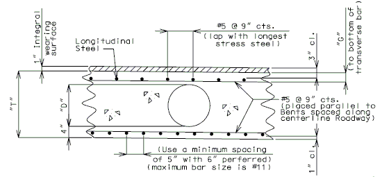
(POSITIVE MOMENT)
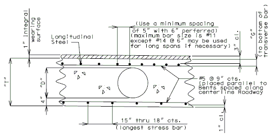
(NEGATIVE MOMENT)
| Longitudinal Reinforcement (Largest Bar) |
"G" |
| #8 | 3-5/8" |
| #9 | 3-3/4" |
| #10 | 3-7/8" |
| #11 | 4" |
| #14 | 4-3/8" |
Moment Curves
| 1. | Determine reinforcing steel from the sum of the dead loads and the live loads + impact (working stress design) or design in accordance with AASHTO Article 8.16 and 8.9 (load factor design). |
| 2. | Determine the cut-off points for the stress bars in sets of 2 or 3. Maximum length = 60'-0", see AASHTO Article 8.24 for extension of reinforcement. |
| 3. | Determine the drop panel width: |
| Minimum width = Column diameter plus 2~6". Maximum width = (Parallel to the centerline of roadway) as determined by deign). | |
| In general, the width of the drop panel normal to centerline bent should be adjusted to 6" increments. |
SOLID SLABS (BOTTOM)
Use AASHTO 3.24.10 Distribution Reinforcement shall be a percentage of positive moment reinforcement (% = 100/√S, with a maximum of 50%).
EDGE BEAM
| Positive Moment: | ||
| The bridge curb is not to be used in determining the resisting moment of the edge beam. | ||
| Dead Load: | Use the same distribution as for the slab design. Use for simple spans 0.1 PS. | |
| Live Load + I: AASHTO Article 3.24.8 | ||
| Use for negative moment on continuous spans 0.1 PS. Use for positive moment on continuous spans 0.08 PS. | ||
| Where | P = Wheel load in pounds, see EPG 751.40.8.5.1.1 Cantilever Moment. | |
| S = Span in feet | ||
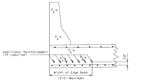
751.40.8.9.1.6 Shear
Shear Loads
The shear in the Hollow Slab should be computed for all loadings H20 and over.
Distribution of Loads
Use the same distribution for the dead and live load as was used for the moment.
Unit Shear Stress
| Load Factor: | |||
| Shear Stress | = | ||
| Working Stress: | |||
| Shear Stress | = | ||
| Where "d" = effective depth, = 0.85 for shear | |||

Allowable Shear Stress
| Load Factor: | |
| Where Vc = shear strength provided by concrete | |
| Working Stress: | |
| Where Vc = Allowable shear stress carried by concrete | |
If shear stress (load) exceeds the allowable shear use one or more of the following solutions.
- Eliminate some voids and replace remainder.
- Shorten alternate voids
- Use shear reinforcing in the critical zone.
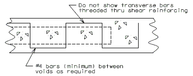
Note:
Consider a voided slab the same as a regular slab as it pertains to the minimum stirrups (AASHTO - Article 8.19).
i.e. The minimum stirrups are not required if the shear stress is less than allowable.
751.40.8.9.1.7 Camber Deflection
Ultimate Deflection:
Compute the "ultimate deflection" at 0.2 points of the spans for the dead loads without the 35# future wearing surface.
Ultimate deflection (long term) = elastic deflection x 3
| Ec (Elastic Modulus) = | psi (districts 1 and 4) |
| psi (remainder of districts) |
The modulus of elasticity for the use in a continuous structure analysis computer program should be determined as follows:
| = | ||
| = | ||
| = | ||
| Where: | ||
| = | deflection. | |
| = | Ultimate deflection | |
| = | Elastic deflection |
Example No. 1
(Assume bridge is in District 8)
| = | ||
| = |
Therefore, use 2 \times 106 psi for modulus of elasticity in the structure analysis computer program to get ultimate deflection. (*)
Example No. 2
(Assume bridge is in District 1)
| = | ||
| = |
Therefore, use psi for modulus of elasticity in the structure analysis computer program to get ultimate deflection. (*)
(*) Gives long term deflection as output.
751.40.8.9.1.8 Slab Construction Joint Details

(FOR SLAB DEPTHS 17" OR MORE)

(FOR SLAB DEPTHS 16½" OR LESS)
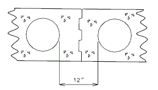
751.40.8.9.2 End Bents
751.40.8.9.2.1 Pile Cap Bents
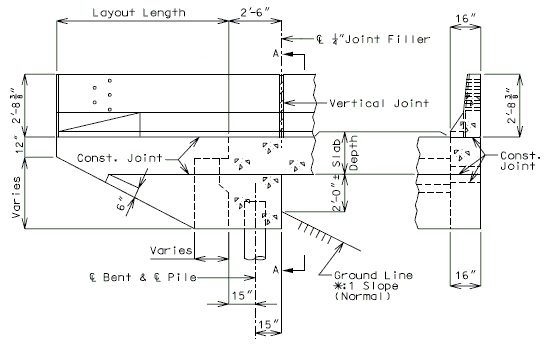
| SECTION THRU WING | SECTION A-A |
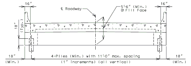

| (1) Wing brace details. | 
|
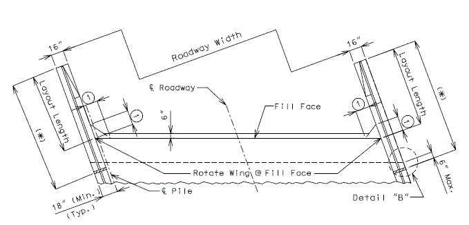
751.40.8.9.2.2 Integral Column Bents
SEISMIC PERFORMANCE CATEGORY A
(PINNED COLUMN AT TOP AND BOTTOM)
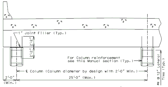
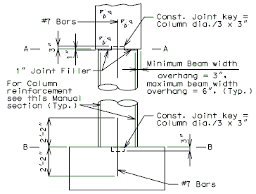 |
|
| SECTION A-A | |
| |
| PINNED COLUMN | SECTION B-B |
Note: If the columns at an end bent have excessive moments due to shortness of the Column or length of the span, they should be detailed as "pinned" and designed for vertical reactions only.
SEISMIC PERFORMANCE CATEGORIES B, C & D
(PINNED COLUMN AT TOP, FIXED COLUMN AT BOTTOM)
For pinned column conditions at the top, see the above details.
For fixed column conditions at the bottom and column reinforcement details.
Note: For details not shown, see integral pile cap details.
751.40.8.9.2.3 Reinforcement - Pile Cap Bents

- SECTION THRU END BENT
(Slab depth less than 16")
- SECTION THRU END BENT

- SECTION THRU END BENT
(Slab depth 16" or more)
- SECTION THRU END BENT
(**) Development length for top bar minimum.
751.40.8.9.2.4 Reinforcement - Wing
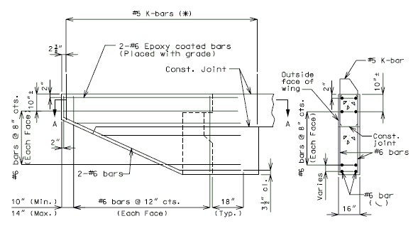
| ELEVATION OF WING | PART SECTION THRU WING |
| (*) Clip K bars as required to maintain minimum clearance at bottom of wing. | |

| SECTION A-A (K-bars not shown for clarity) |
PART SECTION THRU END OF WING |
Note: See _____ for barrier railing details and spacing of K-bars.
751.40.8.9.2.5 Design Assumptions for Integral Piles
Seismic Performance Category A
Piles may be considered as "pinned" (for superstructure) at the pile cap and designed for vertical loads only unless they fall under the following general conditions in which case they should be checked for the loadings as specified for columns.
| 1. | Height from centerline of slab to "pin" is less than 15'. |
| The location of the pinned joint is arbitratily taken as about 1/3 of the length of long piles or at a point about 10' below the natural ground line. | |
| 2. | Piles having a large gross moment of inertia (cast-in-place concrete) gross I of steel BP = I x n. |
| 3. | The number of piles used on a fairly long structure is small. |
Seismic Performance Categories B, C & D
Piles shall be checked for combined axial and bending stresses for seismic loading conditions. For AASHTO group loads I thru VI as applicable, follow criteria noted above for seismic performance category A.
751.40.8.9.3 Intermediate Bents
751.40.8.9.3.1 Integral Bents
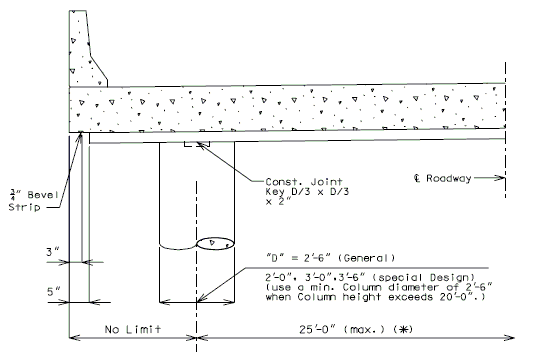
(*) 25'-0" is the max. column spacing allowed. However, the footing pressure may be the controlling factor for the column spacing. It is suggested that a rough check be made of the footing pressure before the spacing is definitely established.
In congested areas, when it is desired to keep the number of columns to a min., larger column spacings may be desirable. (consult the Structural Project Manager).
In general, use two 2'-6" columns for Roadways thru 44'-0" and additional 2'-6" columns for wider Roadways.
SEISMIC PERFORMANCE CATEGORY A


751.40.8.9.3.2 Integral Column Bent with Drop Panel
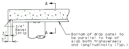 |
ATTENTION DETAILER: When detailing Int. Bents on SPS the Section thru drop panel shall be drawn to appropriate grade. |
| PART SECTION |

| PART SECTION A-A (FLAT) |
PART SECTION A-A (GRADE OR V.C.) D = Diameter of Column |

| PART PLAN - SQUARE | PART PLAN - SKEWED |

|
 |
For Reference Only | ||||||||
|
(*) Based on 3" clearance and #6 stirrups, (includes Integral W.S.) to top longitudinal bar.
(1) Standard 90° Hook.
(2) Const. joint key D/3 x D/3 x 2", D = Diameter of Column
751.40.8.9.3.3 Integral Pile Cap Bents with Drop Panel

| PART SECTION | PART SECTION A-A (FLAT) |
| Bottom or drop panel to be parallel to top of slab both transversely and longitudinally. | 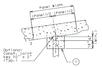
|
| (1)Horizontal except for superelevated structures. | |
| (2) Use 3" Min. clip on beam for skews above 35°. | |
| PART SECTION A-A (GRADE OR V.C.) |

| PART PLAN - SQUARE | PART PLAN - SKEWED |
REINFORCEMENT


(1) Use 5 1/4" for computing length of stirrup bar. Do not detail on plans.
(2) Standard 90° hook.
(3) Optional Const. Joint Key 10" x 2"
751.40.8.9.3.4 Integral Pile Cap Bents without Drop Panel
REINFORCEMENT


(1) Use 5 1/4" for computing length of stirrup bar. Do not detail on plans.
(2) Horizontal except for superelevated structures.
(3) Standard 90° hook.
751.40.8.9.3.5 Pile Footing Design and Details
(1) GENERAL
Number, size and spacing of piling shall be determined by computing the pile loads and applying the proper allowable overstresses.
Cases of Loading (AASHTO Article 3.22)
Group I maximum vertical loads.
Group IV temperature and shrinkage moments with applicable vertical loads.
1983 AASHTO guide specifications for seismic design of highway bridges. (See chapter 4 for earthquake loads combined with applicable vertical loads.) (*) (See Structural Project Manager or Liaison)
Internal stresses including the position of the shear line shall then be computed.
Long narrow footings are not desirable and care should be taken to avoid the use of an extremely long footing 6~0" wide when a shorter footing 8'-3" or 9'-0" wide could be used.
When using the load factor design method for footings, design the number of piles needed based on the working stress design method.
ASSUMPTIONS (Bents with 2 or more columns)
SEISMIC PERFORMANCE CATEGORY A
- Dead and live load moments will be 25% of the moments used for slab and top of Column design.
- Temperature moments shall be 50% of the moment at top of Column.
- Column reinforcement to be same as that required at top of Column. Footing dowel's to be #5 bars, same number as column bars.
- Footings to be proportioned for conditions as specified. Do not use ratio of bent height as specified for Intermediate Bents for longitudinal footings dimensions.
SEISMIC PERFORMANCE CATEGORIES B, C & D
- For Seismic Performance categories B, C & D, the connection between the bottom of Column and the footing is a fixed connection.
- Footing design is based on (Seismic Design of Beam-Column Joint).
(*) The design of all bridges in seismic performance B, C & D are to be designed by earthquake criteria in accordance with EPG 751.9 Bridge Seismic Design.
(2) PILE LOADS
- P = N/n ± M/S
- P = Pile Loads
- N = Vertical Loads
- n = number of piles
- M = overturning moment
- if minimum eccentricity controls the moment in both directions, it is necessary to use the moment in one direction (direction with less section modulus of Pile group) only for the footing check.
- S = Section Modulus of pile group
AASHTO GROUP I AND IV LOADS
Maximum P = Pile Capacity Minimum P = 0
Tension on a pile will not be allowed for any combination of forces.
Overstress reduction will not be used for loading minimums.
EARTHQUAKE LOADS
POINT BEARING PILES
(**) Maximum P = Pile capacity x 2
- (I.E. for HP 10 x 42 piles, maximum P = 56 x 2 = 112 tons/pile).
Minimum P = Use allowable uplift force specified for piles in EPG 751.39 Seal Course.
(**) Two (2) is our normal factor of safety. Under earthquake loadings only the point bearing pile and rock capacities are their ultimate capacities.
FRICTION PILES
Maximum P = Pile capacity
(3) INTERNAL STRESSES
- A) Shear Line
- B) Bending
- C) Distribution of Reinforcement
- D) Shear
751.40.8.9.3.6 Pedestal Pile
GENERAL
No concrete bell shall be used without approval of Structural Project Manager or Liaison.
SEISMIC PERFORMANCE CATEGORY A
- Assume column to be "pinned" for belled footing sitting on rock. All loads will be axial.
- Assume column to be fixed for pedestal pile embedded in rock.
- All earth loads within the diameter of belled footing, or pedestal pile if there is no bell, above ground line shall be included in footing design.

SEISMIC PERFORMANCE CATEGORY B, C & D
See (Seismic Design).
DETAILS
SEISMIC PERFORMANCE CATEGORY A

| Diameter of Shaft |
Minimum Bell Diameter |
Maximum Bell Diameter |
Minimum (*) Reinf. |
Cubic Yards Concrete per ft. |
| 2'-0" | 2'-4" | 6'-0" | 8-#7 | 0.1164 |
| 2'-6" | 2'-10" | 7'-6" | 8-#9 | 0.1818 |
| 3'-0" | 3'-6" | 9'-0" | 11-#9 | 0.2618 |
| 3'-6" | 4'-0" | 10'-6" | 14-#9 | 0.3563 |
| 4'-0" | 4'-6" | 12'-0" | 19-#9 | 0.4654 |
| 4'-6" | 5'-0" | 13'-0" | 24-#9 | 0.5890 |
| 5'-0" | 5'-6" | 14'-0" | 29-#9 | 0.7272 |
| 5'-6" | 6'-0" | 15'-0" | 35-#9 | 0.8799 |
| 6'-0" | 6'-6" | 16'-0" | 41-#9 | 1.0472 |
Concrete Quantities shown in table are per linear foot of shaft only. Bell Quantities are not included.
(*) Amount of reinforcing may be increased from that shown to meet the individual job requirements.
Minimum reinforcement meets AASHTO Spec. 8.18 for reinforcement of compression members.
DETAILS
SEISMIC PERFORMANCE CATEGORY B, C & D

| Diameter of Shaft |
Minimum (*) Reinf. |
Cubic Yards Concrete per ft. |
| 2'-0" | 8-#7 | 0.1164 |
| 2'-6" | 8-#9 | 0.1818 |
| 3'-0" | 11-#9 | 0.2618 |
| 3'-6" | 14-#9 | 0.3563 |
| 4'-0" | 19-#9 | 0.4654 |
| 4'-6" | 24-#9 | 0.5890 |
| 5'-0" | 29-#9 | 0.7272 |
| 5'-6" | 35-#9 | 0.8799 |
Concrete Quantities shown in table are per linear foot of shaft only.
(*) Amount of reinforcing may be increased from that shown to meet the individual job requirements.
Minimum reinforcement meets AASHTO Spec. 8.18 for reinforcement of compression members.
(**) Stay in place casing may be used in place of spirals for column diameters greater than 4 foot.
751.40.8.10 Prestressed Concrete I-Girders
751.40.8.10.1 Design
751.40.8.10.1.1 Girder Design
Geometric Dimensions
Girder Analysis (Continuous Span Series)
Stresses due to dead load weight of slab, girder, diaphragms, haunch and forms will be based on simple spans from centerline to centerline of bearings.
Stresses due to dead load weight of curbs, parapet, rails, future wearing surface and outlets will be based on continuous composite spans with loads equally distributed to all girders. The span lengths used in these computations will be based on the distance from the centerline of the bearing at the End Bent to the centerline of the Int. Bent, and from centerline of Int. Bent to centerline of Int. Bent.
Stresses due to live load plus impact will be based on continuous composite spans whose lengths are described above for curbs, etc.
The analysis will be made on the basis of transformed areas of all steel (both strands and bars) in the section using concrete with = 6.
In composite design, allowances shall be made for the difference in modulus of elasticity of slab and girder by using the effective slab area as specified for concrete T-Beams as given in the current AASHTO Specifications, multiplied by the factor . The area shall include the transformed area of all longitudinal reinforcing bars within the effective width. The 1" integral wearing surface shall not be used in the effective slab depth.
Effective Flange Width
The effective flange width for Beam Types 2,3,4 & 6 should be calculated using AASHTO 8.10.1. For Beam Type 7, the effective flange width should be calculated using AASHTO 9.8.3.
Continuity at Intermediate Supports
Continuity will be obtained at intermediate supports by pouring a concrete diaphragm monolithic with the deck slab and encasing the prestressed girders. Reinforcing bars will tie the slab, diaphragms and girders together.
Reinforcing bars, = 60,000 psi, will be placed in the deck slab for tensile steel.
The ultimate negative moments should be 2.17 times the maximum live load moments including impact and 1.3 times moments for future wearing surface and dead load of barrier or railing.
The area of longitudinal reinforcing steel at the centerline of the intermediate bent should be determined on the basis of a cracked section. This area of reinforcing bars is to be provided by adding additional bars between the normal longitudinal bars at the top of the slab. #8 maximum bar size for additional bars over bents.
These special negative moment reinforcing bars should be ended by one of the following criteria (whichever is greater):
- Where the stress on the normal longitudinal reinforcing bars does not exceed 24,000 psi. as based on a cracked section, plus 15 bar diameters or development length.
- Not closer to the centerline of the intermediate bent than 1/10 of the span. (8' min.)
The concrete stress at the bottom of the girder should be checked at a point 70 strand diameters plus 9 inches from the centerline of the intermediate bent to see that the total compressive stress due to prestress and negative moment does not exceed 3,000 psi. (AASHTO. 9.7.2)
The positive moment at the intermediate bent should be provided for by extending the top two rows of the top strands (both straight or deflected) and if available, the number of bottom strands indicated in tables below bent to form a right angle hook.
Design of Negative Moment Reinforcement
Since most of the dead load moments are carried by the beam acting as a simple span, the negative design moment over piers is the live load plus impact moment. In most designs, the dead load applied after continuity is achieved should also be considered in the negative design moment. The effect of initial precompression due to prestress in the precast girders may be neglected in the negative moment computation of ultimate strength if the maximum precompression stress is less than and the continuity reinforcement is less than 1.5 percent.
It will usually be found that the depth of the compression block will be less than the thickness of the bottom flange of the precast girder. For this reason, the negative moment reinforcement required can be determined by assuming the beam to be a rectangular section with a width equal to the bottom flange width of the girder. Due to the lateral restraint of the diaphragm concrete, ultimate negative compression failure in the PCA tests always occurred in the girders, even though the diaphragm concrete strength was about 1000 psi less than that of the girder concrete for this reason, it is recommended that the negative moment reinforce-ment be designed using the compressive strength of the girder concrete.
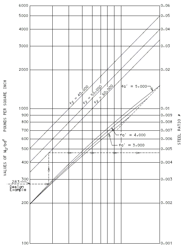
| Web Thickness (Inches) |
Number of Bottom Strands for Positive Moment Connection (C) for Closed Diaphragms | ||||
|---|---|---|---|---|---|
| Beam Type 2 or Modified |
Beam Type 3 or Modified |
Beam Type 4 or Modified |
Beam Type 6 or Modified |
Beam Type 7 or Modified | |
| 6 | 6 | 8 | 10 | -- | 18 |
| 6 1/2 | -- | -- | -- | 14 | -- |
| 7 (A) | 8 | 10 | 10 | -- | -- |
| 7 1/2 (B) | -- | -- | -- | 16 | -- |
| 8 (A) | 8 | 10 | 12 | -- | -- |
| 8 1/2 (B) | -- | -- | -- | 16 | -- |
| Web Thickness (Inches) |
Number of Bottom Strands for Positive Moment Connection (C) for Open Intermediate Diaphragms with Continuous Superstruecture | ||||
|---|---|---|---|---|---|
| Beam Type 2 or Modified |
Beam Type 3 or Modified |
Beam Type 4 or Modified |
Beam Type 6 or Modified |
Beam Type 7 or Modified | |
| 6 | 12 | 16 | 16 | -- | 22 |
| 6 1/2 | -- | -- | -- | 22 | -- |
| 7 (A) | 12 | 16 | 16 | -- | -- |
| 7 1/2 (B) | -- | -- | -- | 22 | -- |
| 8 (A) | 12 | 16 | 16 | -- | -- |
| 8 1/2 (B) | -- | -- | -- | 22 | -- |
| (A) | Modified Beam Type 2, 3 or 4. |
| (B) | Modified Beam Type 6. |
| (C) | If available, otherwise bend all bottom strands. |
Negative Moment Bar Cut-Off (Working Stress Controlling)
Area of slab bars required and stress in the slab bars are printed in program BR200.
Determine stress of the area of slab bars input into program at a point where the area required is larger than that input.
Interpolate along a straight line to where the stress is 24,000 psi.
Note: Negative moment bar computations use a cracked section analysis to determine stresses.
751.40.8.10.1.2 Allowable Concrete Stresses
The following criteria is shown for clarity and is in accordance with AASHTO 9.15.
- = 5,000 psi, = 4,000 psi
A. Temporary stresses before losses except as noted:
- Compression... (*)
- Tension
- Precompressed tensile zone ....................
- No temporary allowable stresses are specified. See paragraph "B" below.
- In tension areas with no bonded reinforcement...
- Where the calculated tensile stress exceeds this value, bonded reinforcement shall be provided to resist the total tension force in the concrete computed on the assumption of an uncracked section. The maximum tensile stress shall not exceed...
- Precompressed tensile zone ....................
B. Stresses at service loads after losses:
- Compression...
- Tension in the precompressed tensile zone...
- (a) For members with bonded reinf. (**)...
- (b) For members without bonded reinf...
- Tension in other areas
- Tension in other area is limited by the allowable temporary stresses specified in "A" above.
C. Cracking stress:
- Modulus of rupture from tests or (for normal weight concrete)...
D. Negative moment stresses in girders made continuous after deadload of slab is in place:
- Tension in negative moment reinforcement... = 60,000 psi, = 24,000 psi
- Compression in concrete at bottom of girder... = 5,000 psi,
(*) BR200 allows 2% overstress
(**)Strands qualify if not debonded at ends.
751.40.8.10.1.3 Prestress Loss and Prestress Camber
| Reduce to: | = Shrinkage | |
| = Elastic Strain | ||
| = Concrete Creep | ||
| = Steel Creep |
| = | |
| = (Approximate Estimate) | |
| = (Approximate Estimate) | |
| = Concrete stress at centroid of P/S steel at point considered due to P/S and dead load at release. | |
| = (Assume ) | |
| = (Estimate average) | |
| = Concrete stress at centroid of P/S Steel (due to dead load)(Assume fcds = 1/2 fc) | |
| = Initial stress in P/S steel | |
| = | |
| = | |
| = (AASHTO 9.16.2.1) | |
| = |
Total loss due to all causes, except friction, is 34.22 ksi. (Friction losses are applied to post-tensioned girder only.) Use 8.84% for initial loss and 8.84% for final loss for design.
= initial loss
= final loss
= total loss
In the above design example, if tension exceeds AASHTO Specifications, (425 psi for 5,000 psi concrete) the girder will have to be modified to limit stress to 425 psi.
| = 6,000 psi | |
| = 4,500 psi | |
| Grade 270 low relaxation strands | |
| = (Estimated average) | |
| = | |
| = | |
| AASHTO 9.16.2.1.3: (approximate estimate) | |
Reduce to:
| = (estimated average) | |
| = |
= Initial stress in low relaxation strands stressed to 75% of ultimate (*)
= 270,000 psi \times 75% = 202,500 psi
= total loss except friction
Use 9.44% for initial loss and 9.44% for final loss.
= initial loss
= final loss
= total loss
P/s force initial =
P/s force final =
(*) Suggested by FHWA: when using 3/8" round strands, max. , whichever is smaller. Larger initial stresses will cause debonding.
Prestress Concrete Girder Formula for Stress Calculation
(-) Tension; (+) Compression
Temp. Stress
| Allow Top | tension for | |
| Bottom | compression for |
- Temp. Top =
- Temp. Bottom =
Design Load Stress
| Allow Top | compression for | |
| Bottom | tension for |
- Top final =
- Bottom final =
- 0.153 sq. in. = Area of one 1/2 inch strand
- 270 ksi = f's = Ult, Str. P/S Strand
- 202.5 ksi = 0.75 (270) = Initial steel stress
- 0.0884 = 8.84% Initial loss - low relaxation
- 0.0884 = 8.84% Final loss - low relaxation
- 4 Str. 2 Draped
- 202.5 (0.153) = 30.98 kips/Str. P/s force
- 6 Strands (30.98) = 185.90 P/s force
| = Area Composite | |
| = Area Girder | |
| = Eccentricity of prestress force of composite section | |
| = Eccentricity of prestress force of non-composite section | |
| = Composite dead load moment | |
| = Girder dead load moment | |
| = Live load + impact moment | |
| = Slab + diaphragm moment | |
| = Prestress forces in girder | |
| = Composite section modulus at bottom of girder | |
| = Non-composite section modulus at bottom of girder | |
| = Composite section modulus at top of girder | |
| = Non-composite section modulus at top of girder |
Prestress Camber
Reference: Computer Program BR139B
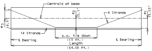
Used to resist uplift before beam is set on bent.
Used after beam is in place.
| Mult. factor |
| ||||||||||||||||||
| = 1.77 | |||||||||||||||||||
| =2.718 | |||||||||||||||||||
| = \varepsilon\ creep \times E_{28\ days} | |||||||||||||||||||
| = (See page 3 PCA design of precast prestressed concrete girders. Use 40% factor based on creep at erection for 28 days.) | |||||||||||||||||||
The following formulas are used to determine:
- Camber due initial strand stress (inch),
- deflection due beam weight (inch),
- camber due strands, beam weight and 28 day creep (inch),
- camber L/4 due strands, beam weight and 28 day creep (inch),
- deflection due to slab weight (inch),
- camber centerline due strands, beam weight, 28 day creep, slab and diaphragm (inch), and
- camber quarterpoint due strands, beam weight, 28 day creep, slab and diaphragm (inch).
Formulas used:
Positive deflect up
Negative deflect down
Beam weight camber
Slab weight camber
Force straight strands (1/2" low relaxation strands)
Force draped strands ( 1/2 " low relaxation strands)
| = dist. centroid beam to centroid straight strand (in.) | |
| = dist. centroid beam to low centroid draped at center of beam (in.) | |
| = dist. centroid beam to up centroid draped at end of beam (in.) | |
| = length (ft.) (cneterline bearing to centerline bearing). | |
| = moment of inertia (in.2) non-transformed. | |
| = moment of inertia (in.2) transformed. | |
| = concentrated loads due to variable slab thickness on each end. | |
| = dist. from centerline brg. to Ps. | |
| = concentrated load due to diaphragm at center of span (kips) | |
| = uniform beam load (kips/ft.) | |
| = uniform slab load (kips/ft.) | |
| = factor for 28 day creep | |
| = modulus of elasticity corresponding to initial girder concrete strength | |
| = modulus of elasticity corresponding to final girder concrete strength |
Note: Compute and show on plans camber at 1/4 points for bridges with spans less than 75', 1/10 points for spans 75' and over.
751.40.8.10.1.4 Superstructure Design
Live Load Distribution
The live load distribution to girders may be assumed to be the same as the AASHTO distribution for concrete floors on steel I-Beam stringers. These factors may be found in EPG 751.40.8.2 Distribution of Loads.
Ultimate Load Capacity
The ultimate load capacity shall be not less than 1.3 times (the weight of the girder plus the weight of the slab and diaphragms plus the weight of the future wearing surface) plus 2.17 times the design live load plus impact.
Ultimate Strength
The ultimate moment on a prestressed girder as determined in accordance with the ultimate load capacity indicated above, shall not be greater than the ultimate strength determined as follows:
| Where | Where | |
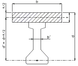 |
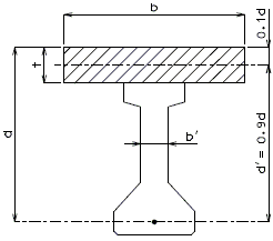
| |
or |
Use the lesser in each case |
or |
Where:
| = Area of p/s strands in bottom flange | |
| , , & | = as shown above |
| = Ultimate strength of p/s strands | |
| = Ultimate strength of slab concrete = 4,000 psi |
Maximum Prestressing Steel Area
- When
- When
In lieu of the above, AASHTO - Article 9.17 & 9.18 may be used. (This is the method used by computer program BR200)
751.40.8.10.1.5 Web Reinforcement
(5" Min. - 21" Max. bar spacing for #4 bars) (5" Min. - 24" Max. bar spacing for #5 bars)

(*) Prestressed concrete members shall be reinforced for diagonal tension stresses. Shear reinforcement shall be placed perpendicular to the axis of the member. The formula to be used to compute areas of web reinforcement is as follows:
- Where but not more than
- But shall not be less than .
(**) Since large moments and large shears occur in the same area of the girder near the interior supports, the AASHTO formula (AASHTO - 9.20 -Shear) for computing the area of web reinforcement has been modified. The formula to be used to compute areas of web reinforcement near interior supports is as follows:
The value "jd" is the distance from the slab reinforcement to the center-of-gravity of the compression area under ultimate loads.
Use #4 shear reinforcement when possible. Alternate B1 bar will not work with #5.
Anchorage Zone Reinforcement - AASHTO Article 9.21.3
The following detail meets the criteria for anchorage zone reinforcement for pretensioned girders (AASHTO Article 9.21.3) for all MoDOT standard girder shapes.
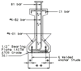
|
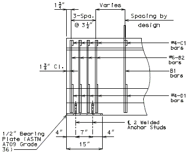
|
| * | 2 3/4" (Type 2, 3 & 4) 5 1/4" (Type 6) |
| ** | 15 1/2" (Type 2, 3 & 4) 22 1/2" (Type 6) |
Sole Plate Anchor Studs
The standard 1/2" sole plate will be anchored with four 1/2" x 4" studs.
Studs shall be designed to meet the criteria of AASHTO Div. I-A in Seismic Performance Category C or D.
Stud capacity is determined as follows:
Where:
| = no. of studs | |
| = area of stud | |
| = yield strength of stud (50 ksi) | |
| = Allowable Shear in Pins AASHTO Table 10.32.1A | |
| = seismic overload factor |
If required, increase the number of 1/2" studs to six and space between open B2 bars. If this is still not adequate, 5/8" studs may be used. The following table may be used as a guide to upper limits of dead load reactions:
| The minimum 3/16" fillet weld between the 1/2" bearing plate and 1 1/2" sole plate is adequate for all cases. |
| ||||||||||||||||||||||
751.40.8.10.1.6 Strands – Miscellaneous
Detensioning
In all detensioning operations the prestressing forces must be kept symmetrical about the vertical axis of the member and must be applied in such a manner as to prevent any sudden or shock loading.
General Information
Splicing:
One approved splice per pretensioning strand will be permitted provided the splices are so positioned that none occur within a member. Strands which are being spliced shall have the same "Twist" or "Lay". Allowance shall be made for slippage of the splice in computing strand elongation.
Wire failure:
Failure of one wire in a seven wire pretensioning strand may be accepted, provided that, it is not more than two percent of the total area of the strands.
Sand Blasting:
On structures where it is questionable as to the clarity of areas to be sandblasted: show limits of sandblasted area in a plan view of details on girder ends (bent sheet). However, generally, sandblasting is covered by Missouri Standard Specification 705.4.14.
751.40.8.10.2 Length
751.40.8.10.2.1 Structure Length

(Integral End Bents)

(Non-Integral End Bents)
751.40.8.10.3 Miscellaneous Details
751.40.8.10.3.1 Shear Blocks
A minimum of two Shear Blocks 12" wide x ![]() high by width of diaphragm, will be detailed at effective locations on open diaphragm bent caps when adequate structural restraint cannot be provided for with anchor bolts.
high by width of diaphragm, will be detailed at effective locations on open diaphragm bent caps when adequate structural restraint cannot be provided for with anchor bolts.

| Height of shear block shall extend a minimum of 1" above the top of the sole plate. |
751.40.8.10.3.2 Anchor Bolts
Simple Spans
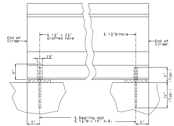
| |
| Expansion | Fixed |
|---|---|
| Part Elevation | |
| Note: | It is permissible for the reinforcing bars and or the strands to come in contact with the materials used in forming A.B. holes. |
| If A.B. holes are formed with galvanized sheet metal, the forms may be left in place. | |
| Hole (1 1/2" round) to be grouted with approved non-shirk grout. |
751.40.8.10.3.3 Dowel Bars
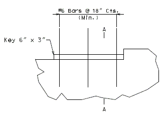
|
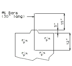
|
| Part Elevation (Fixed Bent) (*) |
Section A-A (*) |
|---|
| (*) | Details shown are for SPC A and B only. |
Dowel bars shall be used for all fixed intermediate bents under prestressed superstructures.
Seismic Performance Category A:
- Use #6 Bars @ 18" Cts. for dowel bars.
Seismic Performance Category B:
- Dowel bars shall be determined by design. (#6 Bars @ 18" Cts. minimum)
- Design dowel bars for shear using service load design.
- Allowable stresses are permitted to increase by 33.3% for earthquake loads.
Seismic Performance Categories C & D:
- See Structural Project Manager.
751.40.8.10.3.4 Expansion Device Support Slots
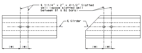
|
| Part Plan of P/S Concrete I-Girder @ Expansion Device End |
|---|
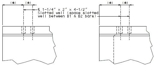
|
| Part Elevation of P/S Concrete I-Girder @ Expansion Device End |
| (*) | Show these dimensions on the P/S concrete girder sheet. |
751.40.8.11 Open Concrete Intermediate Bents and Piers
751.40.8.11.1 Design
751.40.8.11.1.1 General and Unit Stresses
GENERAL
Use Load Factor design method, except for footing pressure and pile capacity where the Service Load design method shall be used.
In some cases, Service Load design method may be permitted on widening projects, see Structural Project Manager.
The terms, Intermediate Bents and Piers, are to be considered interchangeable for EPG 751.40.8.11 Open Concrete Intermediate Bents and Piers.
DESIGN UNIT STRESSES
(1) Reinforced Concrete
Class B Concrete (Substructure) = 1,200 psi = 3,000 psi Reinforcing Steel (Grade 60) = 24,000 psi = 60,000 psi n = 10 (AASHTO Article 8.7.1) (*)
(2) Reinforced Concrete (**)
Class B-1 Concrete (Substructure) = 1,600 psi = 4,000 psi Reinforcing Steel (Grade 60) = 24,000 psi = 60,000 psi = 8 (AASHTO Article 8.7.1) (*)
(3) Structural Steel
- Structural Carbon Steel (ASTM A709 Grade 36)
- = 20,000 psi, = 36,000 psi
(4) Overstress
- The allowable overstresses as specified in AASHTO Article 3.22 shall be used where applicable for Service Load design method.
(*) Use
(**) May be used for special cases, see Structural Project Manager.
751.40.8.11.1.2 Loads
(1) Dead Loads
(2) Live Loads
- As specified on the Bridge Memorandum.
- Impact of 30% is to be used for the design of beam, web supporting beam and top of columns. No impact is to be used for bottom of column, tie beam or footing design.
(3) Wind and Frictional Forces
(4) Temperature and Shrinkage
- The effect of normal and parallel components to the bent shall be considered. When bearings with high friction coefficients are used or for long bridge lengths, the columns and footings are to be analyzed for moments normal to the bent due to the horizontal deflection of the top of the bent.
(5) Buoyancy
- If specified by the Structural Project Manager, or by the Bridge Memorandum.
(6) Earth Pressure
- Bents are to be analyzed for moments due to equivalent fluid pressure on columns and web where the ground line at time of construction, or potential changes in the ground line, indicate.
(7) Earthquake
- See Structural Project Manager or Liaison.
(8) Special Stability Situations
- When indicated by the Bridge Memorandum or by the Structural Project Manager, piers must be analyzed for special loadings as directed (i.e., differential settlement).
(9) Collision
- Where the possibility of collision exists from railroad traffic, the appropriate protection system, for example Collision Wall, shall be provided (See the Bridge Memorandum).
(10) Collision Walls
- Collision walls are to be designed for the unequal horizontal forces from the earth pressure, if the condition exists (See the Bridge Memorandum). The vertical force on the collision wall is the dead load weight of the wall (*). If a bent has three or more columns, design the steel in the top of the wall for negative moment.
(*) For footing design, the eccentricity dead load moment due to an unsymmetrical collision wall shall be considered.
751.40.8.11.1.3 Distribution of Loads
(1) Dead Loads
- Loads from stringers, girders, etc. shall be concentrated loads applied at the centerline of bearing. Loads from superstructure, such as concrete slab spans, shall be applied as uniformly distributed loads.
(2) Live Loads
- Loads from stringers, girders, etc., shall be applied as concentrated loads at the intersection of centerline of stringer and centerline of bent.
(3) Wind and Frictional Forces
(4) Temperature
- Apply at the top of the substructure beam.
(5) Earth Loads
- (a) Vertical
- Vertical earth loads on tie beams shall be applied as uniform loads for a column of earth equal to 3 times the width of the beam. The weight of earth for footing design shall be that directly above the footing, excluding that occupied by the column.
- The earth above the seal courses shall be considered in computing pile loads. Refer to the Design and Dimension of the Pile Footings portion of EPG 751.40.8.13 Concrete Pile Cap Non-Integral End Bents or EPG 751.36 Driven Piles.
- (b) Horizontal
(*) A factor of 2.0 is applied to the moment to allow for the possibility of the column esisting earth pressure caused by the earth behind the column twice the column width.
(6) Earthquake Loads
- See Structural Project Manager or Liaison.
(7) Seal Course
- The weight of the seal course shall not be considered as contributing to the pile loads, except for unusual cases.
751.40.8.11.1.4 Types of Design
TYPES OF DESIGN
Rigid frame design is to be used for the design of Intermediate Bents and Piers.
The joint between the beam and column, and web or tie beam and column,
is assumed to be integral for all phases of design and must be analyzed
for reinforcement requirements as a "Rigid Frame".
The joint between the column and footing is assumed to be "fixed",
unless foundation fexibility needs to be considered (consult Structural
Project Manager for this assessment).
If the distance from the ground line to the footing is large (*),
consideration shall be given to assuming the column to be "fixed" at a
point below the ground line.
(*) When the distance from the ground line to the top of footing is 10' or more, the unsupported height and the fixed point may be measured from the bottom of the beam to the ground line plus 1/2 of the distance from the ground line to the top of the footing.
UNSUPPORTED HEIGHT
Unsupported height is the distance from the bottom of the beam to the top of the footing.
SINGLE COLUMN
Use rigid frame design with the column considered "fixed" at the bottom for all of the conditions.
COLUMN DIAMETER CHANGE
Use a change in column diameter as required by the Bridge Memorandum or column design.
COLUMN SPACING (TRIAL)
(Except Web Supporting Beam type)
Estimate centerline-centerline column spacing for a two column bent as 72% of the distance from the centerline of the outside girder to the centerline of the outside girder.
A three column bent spacing estimation is 44% of the centerline-centerline outside girder spacing.
751.40.8.11.2 Reinforcement
751.40.8.11.2.1 Hammer Head Type
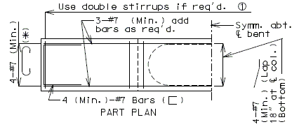 |
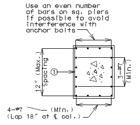
|
| PART PLAN | SECTION A-A |
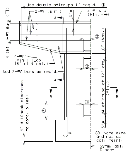 |
Note: When an expansion device in the slab is used at an intermediate bent, all reinforcement located entirely within the beam shall be epoxy coated. See details of protective coating and sloping top of beam to drain. |
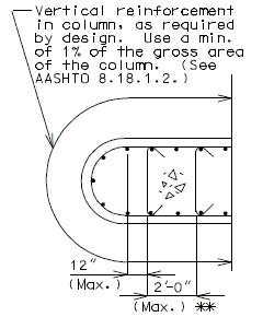
| |
| PART ELEVATION | PART SECTION B-B |
(*) Add hooked reinforcement as required by design.
(**) See AASHTO Article 8.18.2.3.4 for tie requirements.
![]() All stirrups in beam to be the same size bar. (Use a min. spacing of 5" (6" for double stirrups), minimum stirrups are #4 at 12" cts., and maximum
stirrups are #6 at 6" cts.)
All stirrups in beam to be the same size bar. (Use a min. spacing of 5" (6" for double stirrups), minimum stirrups are #4 at 12" cts., and maximum
stirrups are #6 at 6" cts.)
Locate #4 bars (┌─┐) under bearings if required. (Not required for P/S Double-Tee Girders.)
![]() See development length (Other than top bars) or standard hooks in
tension, Ldh.
See development length (Other than top bars) or standard hooks in
tension, Ldh.
751.40.8.11.3 Pile Footings
751.40.8.11.3.1 Design and Dimensions
GENERAL
- Number, size and spacing of piling shall be determined by computing the pile loads and applying the proper allowable overstresses.
- Cases of Loading: (AASHTO Article 3.22)
- Group I and Group II maximum vertical loads (refer to distribution of loads, this Section).
- Group III thru VI wind and/or temperature moments with applicable vertical loads.
- Internal stresses including the position of the shear line shall then be computed.
- Long narrow footings are not desirable and care should be taken to avoid the use of an extremely long footing 6~0" wide when a shorter footing 8'-3" or 9'-0" wide could be used.
- Footings are to be designed for the greater of the minimum moment requirements at the bottom of the column, or the moments at the bottom of the footing.
- When using the load factor design method for footings, design the number of piles needed based on the working stress design method.
PILE LOADS
- Pile Loads - Vertical Loads - Number of Piles - Overturning Moment If minimum eccentricity controls the moment in both directions, It is necessary to use the moment in one direction (direction with less section modulus of pile group) only for the footing check. - Section Modulus of Pile Group
- (A) AASHTO Group I thru VI Loads as applicable
- Maximum = Pile Capacity
- Minimum (zero)
- Tension on a pile will not be allowed for any combination of forces.
- Pile design force shall be calculated with consideration of AASHTO percentage overstress factors.
- (B) Earthquake Loads
See Structural Project Manager or Liaison before using the following seismic information.
- Point Bearing Pile
- Maximum (**)
- (i.e., for HP 10 X 42 piles, Max. tons/pile)
- Minimum = Allowable uplift force specified for piles in this
- Section under Seal Course Design.
- (**) Two "2" is our normal factor of safety. Under earthquake loadings only the point bearing pile and rock capacities are their ultimate capacities.
- Friction Piles
- Maximum = Pile Capacity
- Minimum = Allowable uplift force specified for piles in this
- Section under Seal Course Design.
- See combined axial & bending stresses in Cast-In-Place friction piles in liquefaction areas.
(1) Shear Line
| If the shear line is within the column projected, the footing may be considered satisfactory for all conditions and standard #6 hairpin bars shall be used.
|
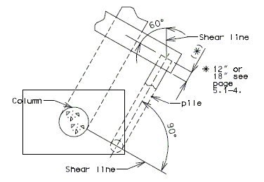
|
(2) Bending
The critical section for bending shall be taken at the face of the columns (concentric square of equivalent area for round columns).
The reinforcement shall be as indicated for reinforced footings, except that the standard #6 hairpin bars may be used for small footings if they provide sufficient steel area.
(3) Distribution of Reinforcement
Reinforcement in Bottom of Footing
Reinforcement shall be distributed uniformly across the entire width of footing in the long direction. In the short direction, the portion of the total reinforcement given by AASHTO Equation 4.4.11.2.2-1 shall be distributed uniformly over a band width equal to the length of the short side of the footing, .
- Band Width Reinforcement =
- where
The remainder of the reinforcement required in the short direction shall be distributed uniformly outside the center band width of footing.
Reinforcement in Top of Footing
Reinforcement in the top of the footing shall be provided based on a seismic analysis for Seismic Performance Categories B, C and D. This reinforcement shall be at least the equivalent area as the bottom steel in both directions. The top steel shall be placed uniformly outside the column.
(4) Shear
(AASHTO Article 8.15.5 or 8.16.6)
The shear capacity of footing in the vicinity of concentrated loads shall be governed by the more severe of the following two conditions.
(i) Beam shear
Critical Section at "d" distance from face of column.
| b = Footing Width Service Load | 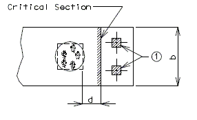
|
| Service Load | |
| Load Factor | |
| PART PLAN OF FOOTING |
|---|
(ii)Peripheral Shear
Critical Section at "d/2" distance from face of column.
| Service Load | 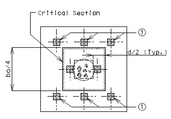
|
| Load Factor | |
| PART PLAN OF FOOTING |
|---|
If shear stress is excessive, increase footing depth.
| Piles to be considered for shear. (Center of piles are at or outside the critical section.) |
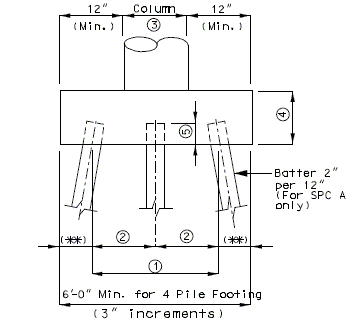 |
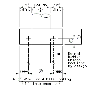
|
| SIDE ELEVATION | FRONT ELEVATION |
|---|
| Min. = 1/8 x (Distance from top of beam to bottom of footing.) | |
| 3'-0" (Min.) & 6'-0" (Max.) for steel HP piles, 14" CIP piles. AASHTO Article 4.5.6.4 shall be considered if piles are situated in cohesive soils. | |
| 3D (Min.) and 6D (Max.) for 20" and 24" CIP piles. (D = pile diameter) | |
| Indicates column diameter, or column length or width on a hammer head pier. | |
| Min. = 2'-6" or column diameter (*) (Or width) for friction piles for SPC A. | |
| Min. = 3'-0" or column diameter (*) (Or width) for steel piles for SPC A. | |
| Min. = 3'-0" or column diameter (*) (Or width) for friction piles for SPC B,C,& D. | |
| Min. = 3'-6" or column diameter (*) (Or width) for steel piles for SPC B, C & D. | |
| 12" for seismic performance category A and 18" for SPC B, C, & D. | |
| (*) | For column diameters 4'-0" and greater use a 4'-0" min. footing thickness. |
| (**) | Use 18" for steel HP piles, 14" CIP piles, prescase and prestress piles. |
TYPICAL PLAN OF
3 PILE FOOTINGS
(minimum pile spacings)
NOTES:
Use 3- piles on exterior foorings only.
Use only HP 10 x 42 or friction piles on three pile footings.
TYPICAL PLAN
STAGGERED PILE
(7 Pile footings shall not be used.)
| If horizontal thrust requires pile batter- consult the Structural Project Manager. |
(*) The maximum pile spacing is 4'-0".
751.40.8.11.3.2 Reinforcement
Unreinforced Footing - Use only in Seismic Performance Category A
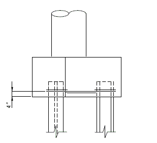
|
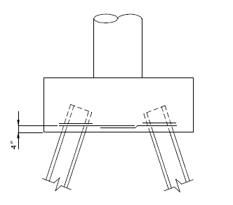
|
| Elevation (3 Pile Footing) |
Elevation (4 Pile Footing |
|---|---|
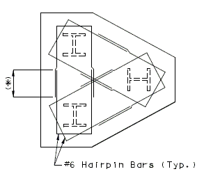
|
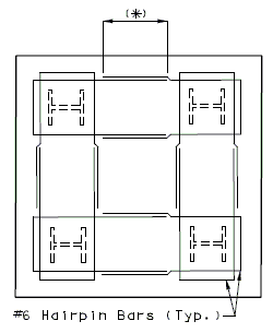
|
| Plan (3 Pile Footing) |
Plan (4 Pile Footing |
| (*) | See lap splice class C (Other than top bars). |
| Notes: | Reiforcement not required by design. Hairpins are sufficient for renforcing requirements. |
| The minimum percentage of reinforcement, "P" , is not required to be met, unless scour is anticipated. | |
| Use for all types of piling, except timber. |
Reinforced Footing - Seismic Performance Category A
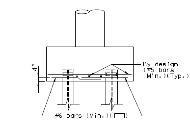
|
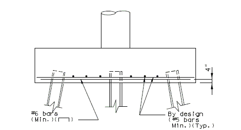
|
| Front Elevation | Side Elevation |
|---|---|
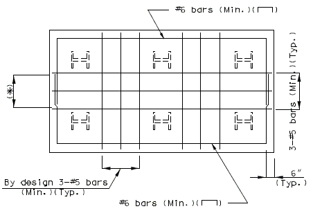
| |
| Plan | |
| (*) | See lap splice class C (Other than top bars). |
| Note: | The maximum size of stress steel allowed is #8 bars. |
Reinforced Footing - Seismic Performance Categorys B, C & D
See Structural Project Manager or Liaison before using the following seismic details.
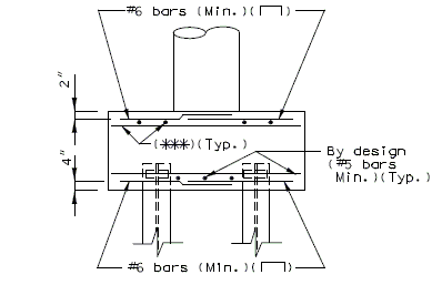
|
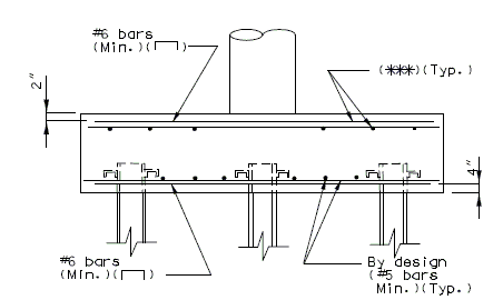
|
| Front Elevation | Side Elevation |
|---|---|
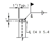
|
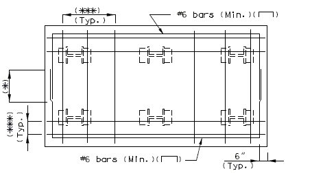
|
| Typical Detail Pile Channel Shear Connector | |
| Plan Showing Top Reinforcement | |
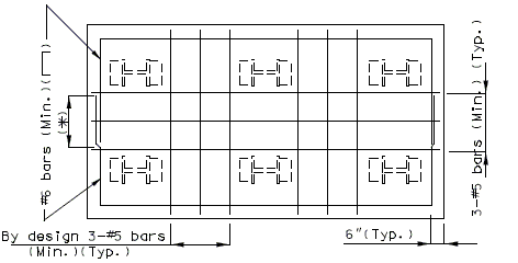
| |
| Plan Showing Bottom reinforcement | |
| (*) | For reinforcement in top of the footing, see lap splice class C (Top bars). |
| (**) | Place the top reinforcement uniformly outside the column. |
| (***) | Use same area of steel in the top of the footing as is required for the bottom. |
| Notes: | For reinforcement in bottom of the footing, see lap splice Class C (Other than top bars). |
| The maximum size of stress steel allowed is #8 bars. | |
| Unreinforced footings shall not be used in seismic performance categories B, C & D. |
751.40.8.11.4 Spread Footings
751.40.8.11.4.1 Design and Dimensions
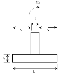
|
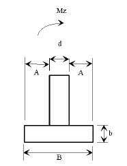
|
| Side Elevation | Front Elevation |
|---|
| d | = column diameter |
| L | = footing length |
| b | = footing depth |
| B | = footing width |
| A | = edge distance from column |
The calculated bearing pressure shall be less than the ultimate capacity of the foundation soil. The ultimate capacity of the foundation soil can be conservatively estimated as 2.0 times the allowable bearing pressure given on the Bridge Memorandum. The analysis method of calculating bearing pressures is outlined in the following information.
Dimensional Requirements
| L - | Minimum of 1/6 x distance from top of beam to bottom of footing (3" increments); |
| B - | Minimum footing width is column diameter + 2A, (3" increments); |
| A - | Minimum of 12"; |
| b - | Minimum of 30" or column diameter, Maximum of 72" at 3" increments; (for column diameters 48" and greater use a 48" minimum footing depth.) |
Size
The size of footing shall be determined by computing the location of the resultant force and by calculating the bearing pressure.
Long, narrow footings are to be avoided, especially on foundation material of low capacity. In general, the length to width ratio should not exceed 2.0, except on structures where the ratio of the longitudinal to transverse loads or some other consideration makes the use of such a ratio limit impractical.
Location of Resultant Force
The location of the resultant force shall be determined by the following equations.
The Middle 1/3 is defined as:
The Middle 1/2 is defined as: and
The Middle 2/3 is defined as: and
The following table specifies requirements for the location of the resultant force.
| Soil Type | Resultant Location Group I - VI | Resultant Location Earthquake Loads Categories B, C and D |
|---|---|---|
| Clay, clay and boulders, cemented gravel, soft shale with allowable bearing values less than 6 tons, etc. | middle 1/3 | middle 1/2 |
| Rock, hard shale with allowable bearing values of 6 tons or more. | middle 1/2 | middle 2/3 |
Bearing Pressure
The bearing pressure for Group I thru VI loads shall be calculated using service loads and the allowable overstress reduction factors as specified in AASHTO Table 3.21.1A. The calculated bearing pressure shall be less than the allowable pressure given on the Bridge Memorandum.
The bearing pressure for Earthquake Loads in Categories B, C, and D shall be calculated from loads specified in AASHTO Division I-A Seismic Design, Sections 6.2.2, 7.2.1, and 7.2.2. The seismic design moment shall be the elastic seismic moment (EQ) divided by the modified response modification factor R'. The modified seismic moment shall then be combined independently with moments from other loads:
Group Load =
Where:
| = dead load | |
| = buoyancy | |
| = stream flow pressure | |
| = elastic seismic moment | |
| = earth pressure | |
| = R/2 for category B | |
| = 1 for categories C and D | |
| = Response Modification Factor | |
| = 5 for multi-column bent | |
| = 3 for single-column bent | |
The calculated bearing pressure shall be less than the ultimate capacity of the foundation soil. The ultimate capacity of the foundation soil can be conservatively estimated as 2.0 times the allowable bearing pressure given on the Bridge Memorandum. The analysis method of calculating bearing pressures is outlined in the following information.
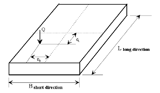
| For | For |
|---|---|
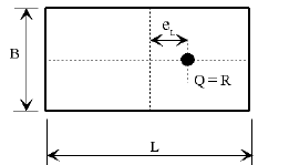
|
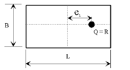
|
| Plan View | Plan View |
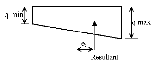
|
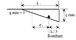
|
| Bearing Pressure | Bearing Pressure |
| CASE 1 | CASE 2 | |
|---|---|---|
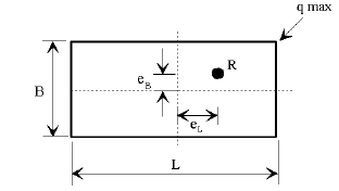
|
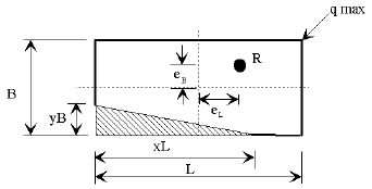
| |
| k, x and y from AASHTO chart | ||
| CASE 1 Plan View | CASE 2 Plan View | |
| CASE 3 | CASE 4 | |
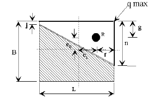
|
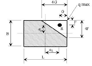
| |
| CASE 3 Plan View | CASE 4 Plan View | |
Loading Cases
Loads for Groups I thru VI shall be calculated for all bridges.
Earthquake loads shall be calculated when the bridge is in Seismic Zones B, C, and D.
Loads for other group loadings shall be used on a case by case basis.
Reinforcement
The footing is to be designed so that the shear strength of the concrete is adequate to handle the shear stress without the additional help of reinforcement. If the shear stress is too great, the footing depth should be increased.
Shear
The shear capacity of the footings in the vicinity of concentrated loads shall be governed by the more severe of the following two conditions.
Critical section at "d" distance from face of column:
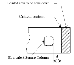
|
| Load Factor |
|---|
| = footing width |
Critical section at "d/2" distance from face of column:
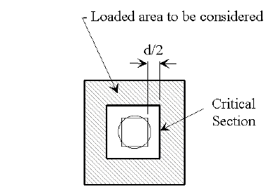
|
| Load Factor |
|---|
| If shear stress is excessive, increase footing depth. | |
Bending
If the shear line is within the projected equivalent square column, the footing may be considered satisfactory for all conditions. (minimum reinforcement required)
If the shear line is outside of the projected column, the footing must be analyzed and reinforced for bending and checked for shear stress.

The critical section for bending shall be taken at the face of the equivalent square column. The equivalent square column is the theoretical square column which has a cross sectional area equal to the round section of the actual column and placed concentrically.
Reinforcement in Bottom of Footing
The bearing pressure used to design bending reinforcement for Group I thru VI loads shall be calculated using Load Factor Loads.
The bearing pressure used to design bending reinforcement for Earthquake Loads in Categories B, C, and D shall be calculated from the same loads as specified in AASHTO Division 1-A Seismic Design for ultimate bearing pressure.
The bottom reinforcement shall be designed using ultimate strength design.
Distribution of Reinforcement
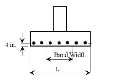
|
| L = Footing Length |
| B = Footing Width |
Reinforcement shall be distributed uniformly across the entire width of footing in the long direction. In the short direction, the portion of the total reinforcement given by AASHTO Equation 4.4.11.2.2-1 shall be distributed uniformly over a band width equal to the length of the short side of the footing, B.
Reinforcement in Top of Footing
Reinforcement in the top of the footing shall be provided for Seismic Performance Categories B, C, and D. This reinforcement shall be the equivalent area as the bottom steel in both directions. The top steel shall be placed uniformly outside the column.
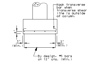
|
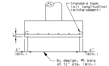
|
| Front Elevation | Side Elevation |
|---|
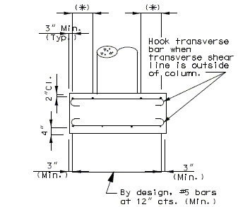
|
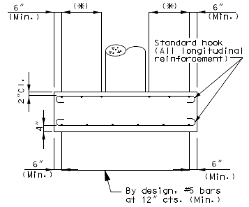
|
| Front Elevation | Side Elevation |
|---|
| (*) | Use same area of steel in the top of the footing as is required for the bottom. |
751.40.8.12 Concrete Pile Cap Intermediate Bents
751.40.8.12.1 Design
751.40.8.12.1.1 Unit Stresses
| (1) | Reinforced Concrete | ||
| Class B Concrete (Substructure) | = 1,200 psi | = 3,000 psi | |
| Reinforcing Steel (Grade 60 | = 24,000 psi | = 60,000 psi | |
| = 10 | |||
| (2) | Structural Steel | ||
| Structural Carbon Steel (ASTM A709 Grade 36) | = 20,000 psi | = 36,000 psi | |
| (3) | Piling | ||
| (4) | Overstress | ||
| The allowable overstresses as specified in AASHTO Article 3.22 shall be used where applicable for service loads. | |||
751.40.8.12.1.2 Loads
| (1) | Dead Loads |
| (2) | Live Load |
| As specified on Bridge Memorandum. | |
| Impact of 30% is to be used for design of the beam. No impact is to be used for design of any other portion of bent including the piles. | |
| (3) | Temperature, Wind and Frictional Loads |
751.40.8.12.1.3 Distribution of Loads
| (1) | Dead Loads |
| Loads from stringers, girders, etc. shall be concentrated loads applied at the intersection of centerline of stringer and centerline of bearing. Loads from concrete slab spans shall be applied as uniformly, distributed loads along the centerline of bearing. | |
| (2) | Live Load |
| Loads from stringers, girders, etc. shall be applied as concentrated loads at the intersection of centerline of stringer and centerline of bearing. For concrete slab spans distribute two wheel lines over 10'-0" (normal to centerline of roadway) of substructure beam. This distribution shall be positioned on the beam on the same basis as used for wheel lines in Traffic Lanes for Substructure Design. | |
| (3) | Temperature, Wind and Frictional Loads |
751.40.8.12.1.4 Design Assumptions
LOADINGS
| (1) | Beam | |
| The beam shall be assumed continuous over supports at centerline of piles. | ||
| Intermediate bent beam caps shall be designed so that service dead load moments do not exceed the cracking moment of the beam cap (AASHTO Article 8.13.3, Eq. 8-2). | ||
| (2) | Piles | |
| (a) | Bending | |
| Stresses in the piles due to bending need not be considered in design calculations for Seismic Performance Category A. | ||
| (b) | Dead Loads, etc. | |
| Dead load of superstructure and substructure will be distributed equally to all piles which are under the main portion of the bent. | ||
751.40.8.12.2 Reinforcement
751.40.8.12.2.1 General
PRESTRESS DOUBLE-TEE STRUCTURES

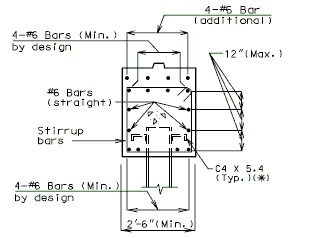
|
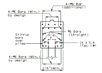
|
| SECTION A-A | SECTION B-B |
| (*) | Channel shear connectors are to be used in Seismic Performance Categories B, C & D. For details not shown, see EPG 751.9 Bridge Seismic Design. |
| (**) | 2'-6" Min. for Seismic Performance Category A. 2'-9" Min. for Seismic Performance Categories, B, C & D. |
| Note: Use square ends on Prestress Double-Tee Structures. | |

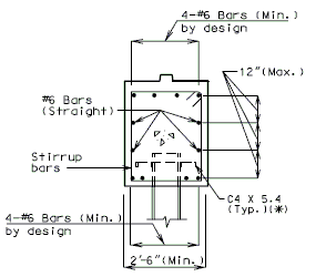 |

|
| SECTION A-A | SECTION B-B |
| (*) | Channel shear connectors are to be used in Seismic Performance Categories B, C & D. |
| (**) | 2'-6" Min. for Seismic Performance Category A. 2'-9" Min. for Seismic Performance Categories, B, C & D. |
| Note: Use square ends on Prestress Double-Tee Structures. | |
751.40.8.12.2.2 Anchorage of Piles for Seismic Performance Categories B, C & D
STEEL PILE

|
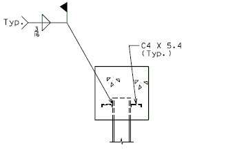
|
| PART ELEVATION | SECTION THRU BEAM |
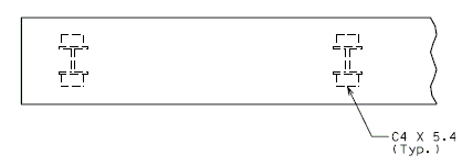
| |
| PART PLAN |
CAST-IN-PLACE PILE
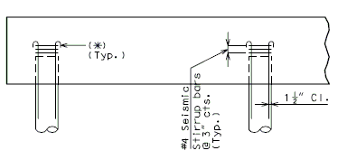
|

|
| PART ELEVATION | SECTION THRU BEAM |

| |
| PART PLAN |
751.40.8.12.2.3 Beam Reinforcement Special Cases
SPECIAL CASE I
If centerline bearing is 12" or less on either side of centerline piles, for all piles (as shown above), use 4-#6 top and bottom and #4 at 12" cts. (stirrups), regardless of pile size.
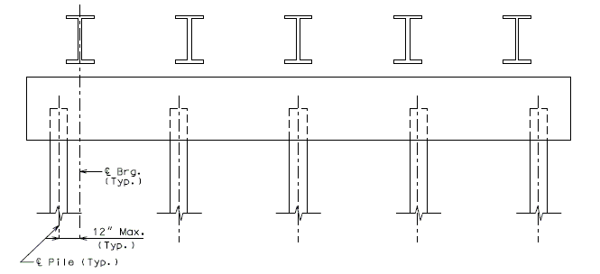
SPECIAL CASE II
When beam reinforcement is to be designed assuming piles to take equal force, design for negative moment in the beam over the interior piles.
(*) Dimensions shown are for illustration purposes only.
751.40.8.12.3 Details
751.40.8.12.3.1 Sway Bracing
Refer to EPG 751.32.3.2.1 Sway Bracing.
751.40.8.12.3.2 Miscellaneous Details for Prestressed Girder
PRESTRESSED GIRDERS (INTEGRAL INT. BENT)

(Continuous Spans - No Longitudinal Beam Steps)
| (*) | ¼ Joint Filler for a P/S Double Tee Structure |
| ½ Joint Filler for a P/S I-Girder Structure |
PRESTRESSED GIRDERS (NON-INTEGRAL INT. BENT)

Longitudinal Beam Step and Shear Blocks shown)
DETAILS OF CONST. JOINT KEY
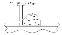
|
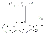
|
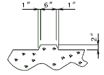
|
| PART ELEVATION | PART SECTION THRU KEYS (P/S I-GIRDERS) |
PART SECTION THRU KEYS (P/S DOUBLE TEE GIRDERS) |
751.40.8.13 Concrete Pile Cap Non-Integral End Bents
751.40.8.13.1 Design
751.40.8.13.1.1 Unit Stresses
| (1) | Reinforced Concrete | ||
| Class B Concrete (Substructure) | = 1,200 psi | = 3,000 psi | |
| Reinforcing Steel (Grade 60) | = 24,000 psi | = 60,000 psi | |
| = 10 | |||
| AASHTO Article 8.7.1) (*) | |||
| (2) | Structural Steel | ||
| Structural Carbon Steel (ASTM A709 Grade 36) | = 20,000 psi | = 36,000 psi | |
| (3) | Piling | ||
| (4) | Overstress | ||
| The allowable overstresses as specified in AASHTO Article 3.22 shall be used where applicable for Service Loads design method. | |||
| (*) | = 145 pcf., for = 150 pcf. | ||
751.40.8.13.1.2 Loads
| (1) | Dead Loads |
| (2) | Live Load |
| As specified on the Bridge Memorandum | |
| Impact of 30% is to be used for design of the beam. No impact is to be used for design of any other portion of bent including the piles. | |
| (3) | Temperature, Wind and Frictional Loads |
| Wind and temperature forces can be calculated based on longitudinal force distribution. |
751.40.8.13.1.3 Distribution of Loads
| (1) | Dead Loads |
| Loads from stringers, girders, etc. shall be concentrated loads applied at the intersection of centerline of stringer and centerline of bearing. | |
| (2) | Live Load |
| Loads from stringers, girders, etc. shall be applied as concentrated loads at the intersection of centerline of stringer and centerline of earing. | |
| (3) | Temperature |
| The force due to expansion or contraction applied at bearing pads are not used for stability or pile bearing computations. However, the movement due to temperature should be considered in the bearing pad design and expansion device design. | |
| (4) | Wing with Detached Wing Wall |

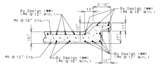
| (*) | Detached wing wall shown is for illustration purpose only. Design detached wing wall as a retaining wall. |
| (**) | See retaining wall design. |
751.40.8.13.1.4 Design Assumptions - Loadings
| 1) | Piles | ||||||||||||||||||||||
| a. | Stresses in the piles due to bending need not be considered in design calculations except for seismic design in categories B, C and D. | ||||||||||||||||||||||
| b. | The following four loading cases should be considered. | ||||||||||||||||||||||
| |||||||||||||||||||||||
| Where, | |||||||||||||||||||||||
| LL | = live load | ||||||||||||||||||||||
| DL | = dead load of superstructure, substructure and one half of the apporach slab | ||||||||||||||||||||||
| SUR | = two feet of live load surcharge | ||||||||||||||||||||||
| E | = dead load of earth fill | ||||||||||||||||||||||
| EP | = equivalent fluid pressure of earth | ||||||||||||||||||||||
| Maximum pile pressure = pile capacity | |||||||||||||||||||||||
| Minimum pile pressure = 0 (tension on a pile will not be allowed for any combination of forces exept as noted) | |||||||||||||||||||||||
| 2) | Analysis Procedure | ||||||||||||||||||||||
| a. | Find the lateral stiffness of a pile, : | ||||||||||||||||||||||
| With fixed pile-head (i.e., only translation movement is allowed but no rotation allowed): The lateral stiffness of a pile can be estimated using Figures 1 and 3 or 2 and 3 for pile in cohesionless or cohesive soil, respectively. The method of using Figures 1, 2, and 3 to find lateral stiffness is called Linear Subgrade Modulus Method. Usually the significant soil-pile interaction zone for pile subjected to lateral movement is confined to a depth at the upper 5 to 10 pile diameters. Therefore, simplified single layer stiffness chart shown in Figure 3 is appropriate for lateral loading. The coefficient in Figures 1 and 2 is used to define the subgrade modulus at depth “z” representing the soil stiffness per unit pile length. For the purpose of selecting an appropriate value, the soil condition at the upper 5 pile diameters should be used. Since soil property, friction angle , or cohesion c, is needed when Figure 1 or 2 is used, determine soil properties based on available soil boring data. If soil boring data is not available, one can conservatively use value of 0.1 in Figure 3. Designer may also use soil properties to convert SPT N value to friction angle , or cohesion c, for granular or cohesive soil, respectively. Figures 1 and 2 were based on test data for smaller-diameter (12 inches) piles, but can be used for piles up to about 24 inches in diameter. In Figure 2, the solid line (by Lam et al. 1991) shall be used in design. | |||||||||||||||||||||||
| b. | Find the axial stiffness of a pile, : | ||||||||||||||||||||||
| For friction pile, may be determined based on a secant stiffness approach as described in EPG 751.9 Bridge Seismic Design or by the in-house computer program “SPREAD” where is calculated as: | |||||||||||||||||||||||
| Equation (1) | |||||||||||||||||||||||
| Where: | |||||||||||||||||||||||
| = cross sectional area of pile | |||||||||||||||||||||||
| = elastic modulus of pile | |||||||||||||||||||||||
| = total length of pile | |||||||||||||||||||||||
| = secant stiffness due to ultimate friction capacity of the pile as described in EPG 751.9.2.6.3 Pile Axial Stiffness | |||||||||||||||||||||||
| = secant stiffness due to ultimate bearing capacity of the pile as described in EPG 751.9.2.6.3 Pile Axial Stiffness | |||||||||||||||||||||||
| For HP bearing pile on rock shall be calculated as: | |||||||||||||||||||||||
| Equation (2) | |||||||||||||||||||||||
| Or Conservatively, may be determined as: | |||||||||||||||||||||||
| Equation (3) | |||||||||||||||||||||||
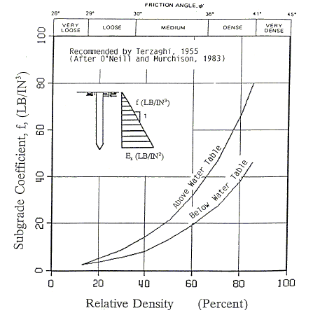
| |||||||||||||||||||||||
| Recommended Coefficient of Variation in Subgrade Modulus with Depth for Sand | |||||||||||||||||||||||
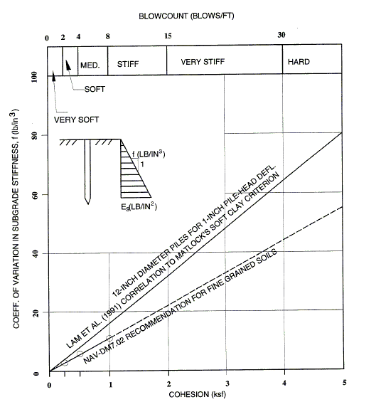
| |||||||||||||||||||||||
| Recommended Coefficient of Variation in Subgrade Modulus with Depth for Clay | |||||||||||||||||||||||
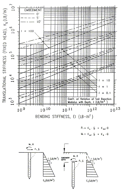
| |||||||||||||||||||||||
| |||||||||||||||||||||||
| Lateral Embedded Pile-Head Stiffness | |||||||||||||||||||||||
| c. | Find the equivalent cantilever pile length, | ||||||||||||||||||||||
| For the structural model used in the structural analyses of loading cases I through IV. As shown in figure below, length L can be calculated as: | |||||||||||||||||||||||
| Equation (4) | |||||||||||||||||||||||
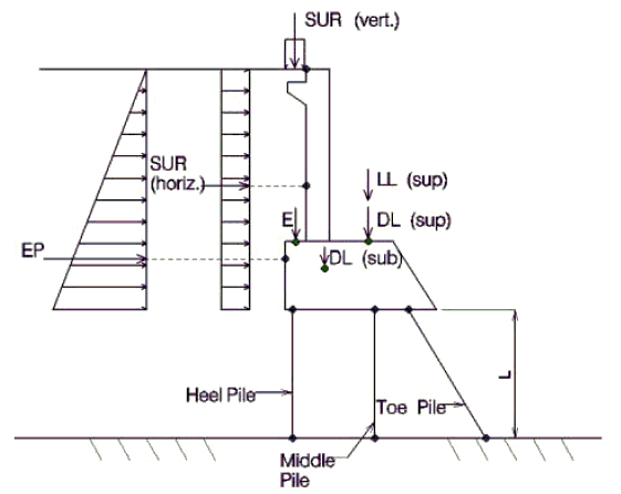
| |||||||||||||||||||||||
| Structural Model | |||||||||||||||||||||||
| d. | Find the equivalent pile area, : | ||||||||||||||||||||||
| Once the equivalent cantilever pile length has been determined from step (c) above, the equivalent axial rigidity of the pile, , can be calculated as . Then, the equivalent pile area, , is equal to | |||||||||||||||||||||||
| Equation (5) | |||||||||||||||||||||||
| e. | Perform structural analyses for loading cases I through IV. | ||||||||||||||||||||||
| Use computer programs STRUCT3D, SAP2000 or any other program capable of running static analysis. | |||||||||||||||||||||||
| f. | Check abutment movement at the top of backwall and at the bottom of beam cap | ||||||||||||||||||||||
| Maximum movement away from the backfill shall not be greater than 1/8". Maximum movement toward the backfill shall not be greater than 1/4". | |||||||||||||||||||||||
| g. | Check pile axial loads from the analysis with the allowable pile axial load capacity. | ||||||||||||||||||||||
| h. | Check overturning of bent | ||||||||||||||||||||||
| Conservatively, use the same equivalent cantilever pile length, . Check overturning of bent at the bottom of toe pile for loading cases I and II(Figure of Structural model). | |||||||||||||||||||||||
| |||||||||||||||||||||||
| 5) | Deadman Anchorage System | ||||||||||||||||||||||
| Deadman anchorage can be used when the abutment movement exceeds the allowable movement. | |||||||||||||||||||||||
| The size and location of deadman anchorage shall be designed appropriately to maintain the stability of the abutment. | |||||||||||||||||||||||
| The deadman forces may be used to resist overturning with the approval of the Structural Project Manager. | |||||||||||||||||||||||
| 6) | Passive Pressure Shear Key (if applicable) | ||||||||||||||||||||||
| Passive pressure shear key may be used when the abutment movement exceeds the allowable movement. | |||||||||||||||||||||||
| The passive resistance of soil to the lateral force at shear keys may be used with the approval of structural project manager. | |||||||||||||||||||||||
751.40.8.13.1.5 Deadman Anchors
Design Assumptions
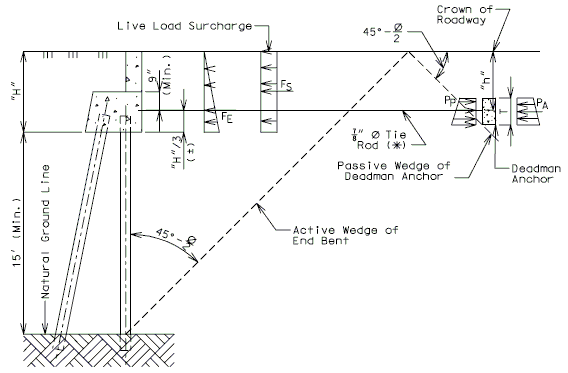
| Length of Deadman = | |
| Number of tie rods required = | |
| = Active earth pressure on deadman, in lb./ft. = (120 pcf) | |
| (**) | = Passive earth pressure on deadman, in lb./ft. = (120 pcf) |
| = Earth pressure on end bent, in lb. = 0.5(120 pcf) (length of beam) | |
| = Surcharge on end bent, in lb. = | |
| (***) | = 8.0 kips for 7/8" Ø tie rod and 10.50 kips for 1" Ø tie rods (Capacity of the tie rods based on a maximum skew of 30°.) |
| * | If the number of 7/8" Ø tie rods causes too long of a deadman, then try 1" Ø tie rods. |
| ** | For seismic loads only, use = 4 kips/sq.ft. as the ultimate capacity of compacted fill. |
| *** | For seismic loads only, the allowable stress in the tie rod may be taken as the yield stress of the rod. |
Notes:
No more than 20% of deadman may fall outside of the roadway shoulders. To prevent more than 20% limit, using a deeper deadman to reduce its length. If this is not possible, the total passive pressure resistance should be calculated by summing the resistance from the different fill depths.
When deadman anchors are to be used, design the piles for a factor of safety of 1.0 for sliding and design deadman anchors to resist all horizontal earth forces with a factor of safety of 1.0. This will result in a factor of safety for sliding of 2.0. For special cases, see the Structural Project Manager.
Design Example
| Assume: | |
| Roadway width = 36', Out-Out slab width = 36' + 2 x 16" = 38.67' | |
| Skew = , Length of Beam = | |
| Beam depth = , , | |
| , use | |
| Assume (Deadman anchor depth) | |
| Determine Earth and Surcharge Forces | |||
| = | |||
| = | |||
| = | |||
| = | |||
| = | |||
| = | |||
| = | |||
| = | |||
| = | |||
| = | |||
| = | |||
| = | |||
| = | |||
| = | |||
| Determine number of Tie Rods required | |
| Try 7/8"Ø Rods: kips | |
| Number of Rods required = | |
| Use 12-7/8"Ø Rie Rods. | |
| Determine length of Deadman | |
| Length of Deadman required = | |
| Tie Rod spacing = minimum, ok. | |
| Length of Deadman provided = | |
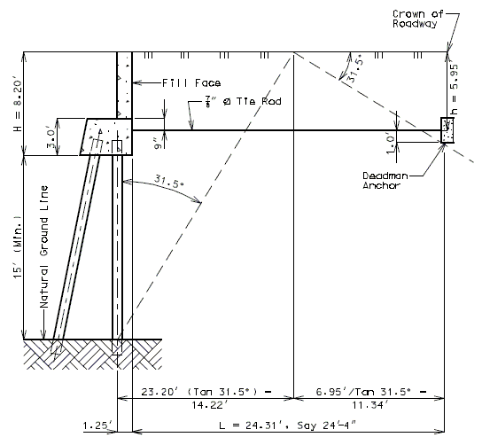
| 1) | Check tie rod skew angle at Fill Face of End Bent | |
| , tie capacity ok. | ||

| ||
| 2) | Check criteria for Deadman Anchors extending into Fill Slope | |
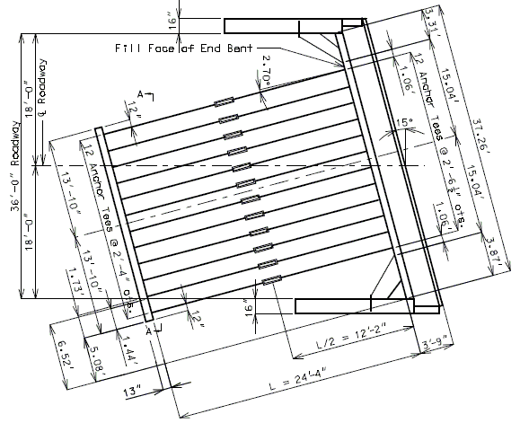
| ||
A) Extension of Deadman into Fill Slope Length of Deadman extending into Fill Slope = 0.2 (Length of Deadman) = Length of Deadman extending into Fill Slope (Length of Deadman), ok Note: See below for Section A-A details. B) Cover of Deadman in Fill Slope
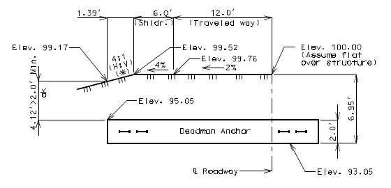
DETAIL AT FILL SLOPE
Note:
(*) Fill slope shown is for illustration purpose only, see roadway plans.
751.40.8.13.2 Reinforcement
751.40.8.13.2.1 Wide Flange Beams, Plate Girders and Prestressed Girders
END BENT WITH EXPANSION DEVICE

|
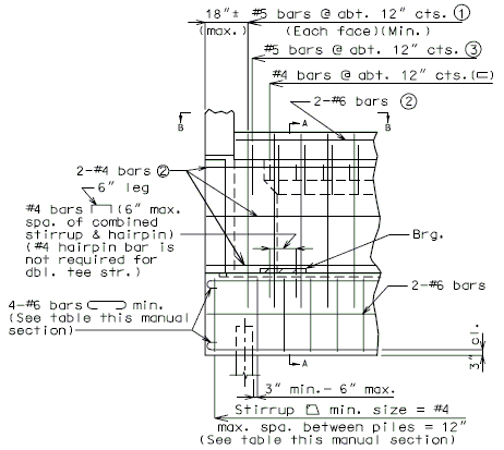
|
| SECTION A-A | |
| PART ELEVATION |
Notes:
(1) See details for reinforcement of end bent backwall.
(2) #6-H bars and #4-H bars in backwall of skewed bridges shall be bent in field if required.
(3) Center #5 bars in backwall.
Epoxy coat all reinforcing in end bents with expansion devices. See ______ for details of protective coating and sloping top of beam to drain.
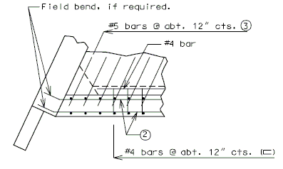
|
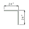
|
| DETAIL OF #5 BARS SHAPE 19 | |
| PART PLAN B-B |
END BENT WITHOUT EXPANSION DEVICE
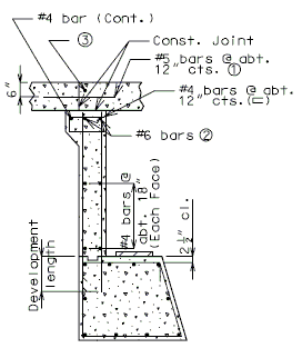
|
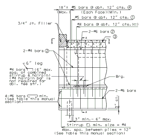
|
| SECTION A-A | |
| PART ELEVATION |
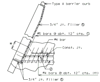
|
| ||||||||||||
| PART PLAN B-B | |||||||||||||
END BENT WING
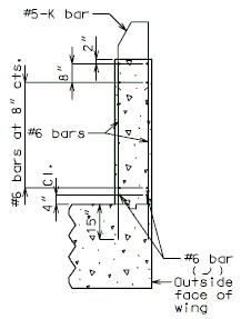 | |
|
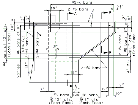
|
| SECTION A-A | |
| TYPICAL ELEVATION OF WING |
Note: (1) Development length
|
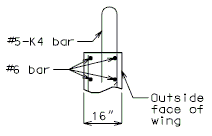
| ||||||||||||
| SECTION B-B | |||||||||||||

|
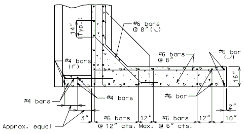
| ||||||||||||
| PART SECTION THRU BENTS WITH PASSIVE PRESSURE | |||||||||||||
| HORIZONTAL SECTION THRU WING (K bars not shown for clarity) |
END BENT BEAM HEEL
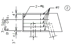
|
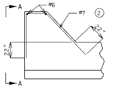
|
| ELEVATION A-A (TYP.) | PART PLAN OF BEAM (SQUARE) |
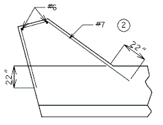
|
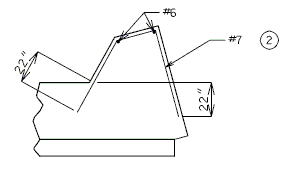
|
| PART PLAN OF BEAM - SKEWS THRU 15° - LEFT ADVANCE SHOWN | |
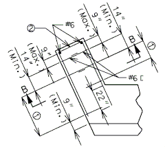
|
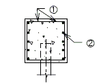
|
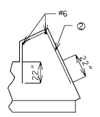
|
| SECTION B-B | ||
| PART PLAN OF BEAM - SKEWS OVER 15° - LEFT ADVANCE SHOWN | ||
Note:
Vertical spacing for #7 bars shown in Elevation A-A is typical for all types of end bent beams.
For a long distance between heel pile and bearing beam investigate for use of larger bars; e.g. larger skews where the shear line does not fall within the bearing beam.
| Pile Load Not Greater | (1) Hair-Pin Stirrups | (2) Horizontal Rebar around Heel Pile | |||
| Skew thru 30° | Skew 31° thru 45° | Skew 46° thru 60° | Skew over 60° | ||
| 140 kips | #6 @ 9" | 5-#7 | 5-#7 | 5-#8 | By Design |
| 194 kips | #6 @ 6" | 5-#7 | 5-#8 | By Design | By Design |
Use 21" horizontal leg.
END BENT BACKWALL
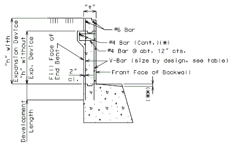
| V-BAR SIZE AND SPACING | |||
| h (feet) |
t (inch) |
Fill Face Reinforcement |
Front Face Reinforcement |
| 1-6 | 12 | #5 @ 12" | #5 @ 12" |
| 7 | 12 | #5 @ 12" | #5 @ 12" |
| 8 | 12 | #5 @ 12" | #5 @ 12" |
| 9 | 12 | #6 @ 12" | #5 @ 12" |
| 10 | 12 | #6 @ 10" | #5 @ 12" |
| 11 | 15 | #6 @ 10" | #5 @ 12" |
| 12 | 15 | #6 @ 8" | #5 @ 12" |
| 13 | 18 | #6 @ 8" | #5 @ 12" |
| 14 | 18 | #6 @ 6" | #5 @ 12" |
Note:
All reinforcement is grade 60.
Design is based on 45 lbs. per cu. ft. equivalent fluid pressure and 90 lbs. per sq. ft. live load surcharge.
Epoxy coat all reinforcing steel in beam and backwall on non-integral end bents with expansion devices.
751.40.8.14 Concrete Pile Cap Integral End Bents
751.40.8.14.1 Design
751.40.8.14.1.1 Design Unit Stresses
- Reinforced Concrete
- Class B Concrete (Substructure) = 1,200 psi, = 3,000 psi
- Reinforcing Steel (Grade 60) = 24,000 psi = 60,000 psi
- = 10
- = (AASHTO Article 8.7.1)(*)
- Structural Steel
- Structural Carbon Steel (ASTM A709 Grade 36) = 20,000 psi = 36,000 psi
- Piling
- See the Bridge Memorandum if pile capacity is indicated.
- Overstress
- The allowable overstresses as specified in AASHTO Article 3.22 shall be used where applicable for Service Loads design method.
(*)
751.40.8.14.1.2 Loads
- Dead Loads
- Live Load
- As specified on the Bridge Memorandum.
- Impact of 30% is to be used for design of the beam. No impact is to be used for design of any other portion of bent including the piles.
- Temperature, Wind and Frictional Loads
751.40.8.14.1.3 Distribution of Loads
- Dead Loads
- Loads from stringers, girders, etc. shall be concentrated loads applied at the intersection of centerline of stringer and centerline of bearing. Loads from concrete slab spans shall be applied as uniformly, distributed loads along the centerline of bearing.
- Live Load
- Loads from stringers, girders, etc. shall be applied as concentrated loads at the intersection of centerline of stringer and centerline of bearing. For concrete slab spans distribute two wheel lines over 10'-0" (normal to centerline of roadway) of substructure beam. This distribution shall be positioned on the beam on the same basis as used for wheel lines in Traffic Lanes for Substructure Design.
- Wing with Detached Wing Wall
- When wing length, L, is greater than 17 feet, use maximum length of 10 feet rectangular wing wall combined with a detached wing wall. When detached wing walls are used, no portion of the bridge live load shall be assumed distributed to the detached wing walls. Design detached wing wall as a retaining wall. (The weight of barrier or railing on top of the wall shall be included in Dead Load.)
751.40.8.14.1.4 Design Examples
Design H-bar and F-bar of an intermediate wing as shown in the figures below (wing length = 12.5', wing thickness = 24", wing height = 8'-4"), a Seismic Force of = 12.21 kips/ft. is applied on the wall.
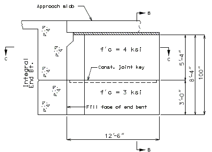
|
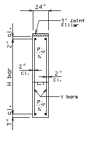
|
| Section Near Intermediate Wing | Section B-B |
|---|---|
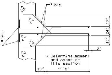
|
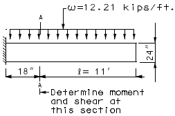
|
| Interior Wing Design | |
| Section C-C | |
Solve: Assume #6 V bar, #8 H bar, #6 F bar
| 1.) | Design H-bar for bending |
| . | |
| At Section A-A: | |
| Use | |
| As (Req'd) = | |
| Try No. 8 @ 9", USE | |
| Say 11 spacings, 12 bars (Each Face) | |
| Total Area = USE 12-No. 8 H-bar (Each Face) |
| 2.) | Design F-bar for shear |
| (AASHTO Article 8.16.6.1.1) | |
| At Section A-A: | |
| No needed by AASHTO Article 8.16.6.3.1. | |
| Minimum shear reinforcement is required by AASHTO Article 8.19.1.1(a).(ACI 318-95 11.5.5.1) | |
| F-bar is a single group of parallel bars, all bent up at the same distance from support (no "spacing" along the "L" direction of the wing). | |
| Try No. 6 @ 12" F-bar (each face). | |
| Try say 8 spacing, 9 bars (each face). | |
| Since seismic force is a cyclic loading, assume one bar works at any instance. | |
| Check | |
| O.K. by AASHTO Article 8.16.6.3.4. | |
| USE 9 No. 6 F-bars (each face). |
751.40.8.14.2 Reinforcement
751.40.8.14.2.1 Earthquake Loads at End Bent – Intermediate Wing (Seismic Shear Wall)
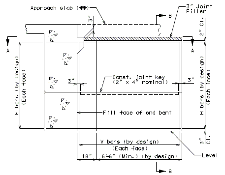
|
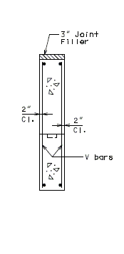
|
| Section Near Intermediate Wing | Section B-B |
|---|---|
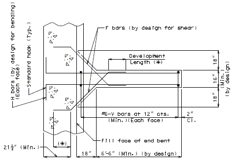
|
|
| Section A-A | |
| * | Use 1.25 x development length for seismic design. |
| ** | Additional reinforcing steel by design if required. |
| Note: | Make sure reinforcement does not interfere with girders. |
751.40.8.15 Cast-In-Place Concrete Retaining Walls
751.40.8.15.1 Loads
Dead Loads
Dead loads shall be determined from the unit weights in EPG 751.2.1.1 Dead Load.
Equivalent Fluid Pressure (Earth Pressures)
| Additional Information |
| AASHTO 3.20.1 |
For determining equivalent earth pressures for Group Loadings I through VI the Rankine Formula for Active Earth Pressure shall be used.
Rankine Formula: where:
- Ca = = coefficient of active earth pressure
- Pa = equivalent active earth pressure
- H = height of the soil face at the vertical plane of interest
- = unit weight of soil
- = slope of fill in degrees
- = angle of internal friction of soil in degrees
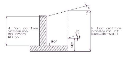
Example
Given:
- δ = 3:1 (H:V) slope
- ϕ = 25°
- γs = 0.120 kcf
- H = 10 ft
δ = arctan = 18.4°
Ca = = 0.515
Pa = (1/2)(0.515)(0.120 kips/ft3)(10 ft)2 = 3.090 kips per foot of wall length
The ϕ angle shall be determined by the Materials Division from soil tests. If the ϕ angle cannot be provided by the Construction and Materials Division a ϕ angle of 27 degrees shall be used.
Drainage shall be provided to relieve water pressure from behind all cast-in-place concrete retaining walls. If adequate drainage can not be provided then walls shall be designed to resist the maximum anticipated water pressure.
Surcharge Due to Point, Line and Strip Loads
Surcharge due to point and line loads on the soil being retained shall be included as dead load surcharge. The effect of these loads on the wall may be calculated using Figure 5.5.2B from AASHTO.
Surcharge due to strip loads on the soil being retained shall be included as a dead load surcharge load. The following procedure as described in Principles of Foundation Engineering by Braja M. Das (1995) shall be applied to calculate these loads when strip loads are applicable. An example of this application is when a retaining wall is used in front of an abutment so that the wall is retaining the soil from behind the abutment as a strip load on the soil being retained by the wall.
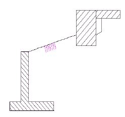
The portion of soil that is in the active wedge must be determined because the surcharge pressure only affects the wall if it acts on the active wedge. The actual failure surface in the backfill for the active state can be represented by ABC shown in the figure below. An approximation to the failure surface based on Rankine's active state is shown by dashed line AD. This approximation is slightly unconservative because it neglects friction at the pseudo-wall to soil interface.
The following variables are shown in the figure below:
- β = slope of the active failure plane in degrees
- δ = slope of fill in degrees
- H = height of the pseudo-wall (fom the bottom of the footing).
- L1 = distance from back of stem to back of footing heel
- L2 = distance from footing heel to intersection of failure plane with ground surface
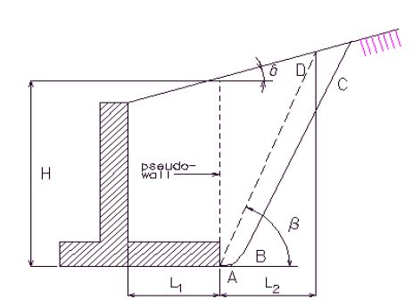
In order to determine β, the following equation which has been derived from Rankine's active earth pressure theory must be solved by iteration:
- ϕ = angle of internal friction of soil in degrees
A good estimate for the first iteration is to let β = 45° + (ϕ/2). In lieu of iterating the above equation a conservative estimate for β is 45°. Once β has been established, an estimate of L1 is needed to determine L2. From the geometry of the variables shown in the above figure:
The resultant pressure due to the strip load surcharge and its location are then determined. The following variables are shown in the figure below:
- q = load per unit area
- Ps = resultant pressure on wall due only to surcharge earth pressure
- = location of Ps measured from the bottom of the footing
- L3 = distance from back of stem to where surcharge pressure begins
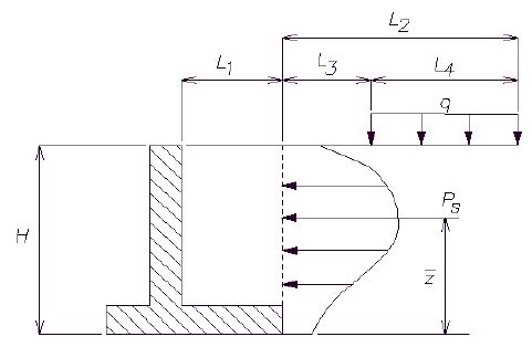
From the figure:
- Ps = where
- where
When applicable, Ps is applied to the wall in addition to other earth pressures. The wall is then designed as usual.
Live Load Surcharge
| Additional Information |
| AASHTO 3.20.3 & 5.5.2 |
Live load surcharge pressure of not less than two feet of earth shall be applied to the structure when highway traffic can come within a horizontal distance equal to one-half of the wall height, measured from the plane where earth pressure is applied.
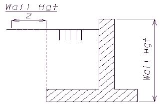
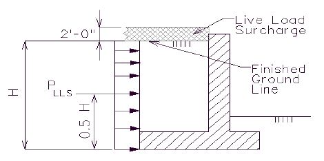
- PLLS = (2 ft.) γs Ca H = pressure due to live load surcharge only
- γs = unit weight of soil (Note: AASHTO 5.5.2 specifies a minimum of 125 pcf for live load surcharge, MoDOT policy allows 120 pcf as given from the unit weights in EPG 751.2.1.1 Dead Load.)
- Ca = coefficient of active earth pressure
- H = height of the soil face at the vertical plane of interest
The vertical live load surcharge pressure should only be considered when checking footing bearing pressures, when designing footing reinforcement, and when collision loads are present.
Live Load Wheel Lines
Live load wheel lines shall be applied to the footing when the footing is used as a riding or parking surface.
| Additional Information |
| AASHTO 3.24.5.1.1 & 5.5.6.1 |
Distribute a LLWL equal to 16 kips as a strip load on the footing in the following manner.
- P = LLWL/E
- where E = 0.8X + 3.75
- X = distance in ft. from the load to the front face of the wall
| Additional Information |
| AASHTO 3.24.2 & 3.30 |
Two separate placements of wheel lines shall be considered, one foot from the barrier or wall and one foot from the toe of the footing.
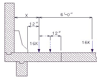
Collision Forces
| Additional Information |
| AASHTO Figure 2.7.4B |
Collision forces shall be applied to a wall that can be hit by traffic. Apply a point load of 10 kips to the wall at a point 3 ft. above the finished ground line.
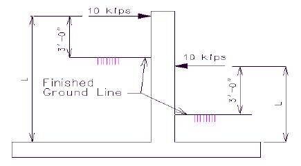
Distribute the force to the wall in the following manner:
- Force per ft of wall = (10 kips)/2L
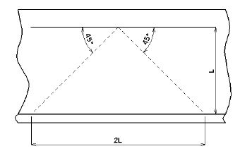
When considering collision loads, a 25% overstress is allowed for bearing pressures and a factor of safety of 1.2 shall be used for sliding and overturning.
Wind and Temperature Forces
These forces shall be disregarded except for special cases, consult the Structural Project Manager.
When walls are longer than 84 ft., an expansion joint shall be provided.
Contraction joint spacing shall not exceed 28 feet.
Seismic Loads
Retaining walls in Seismic Performance Category A (SPC A) and SPC B that are located adjacent to roadways may be designed in accordance with AASHTO specifications for SPC A. Retaining walls in SPC B which are located under a bridge abutment or in a location where failure of the wall may affect the structural integrity of a bridge shall be designed to AASHTO specifications for SPC B. All retaining walls located in SPC C and SPC D shall be designed in accordance to AASHTO specifications for the corresponding SPC.
In seismic category B, C and D determine equivalent fluid pressure from Mononobe-Okabe static method.
| Additional Information |
| 1992 AASHTO Div. IA Eqns. C6-3 and C6-4 |
PAE = equivalent active earth pressure during an earthquake
PAE = 0.5 γsH2(1 - kv)KAE where
KAE = seismic active pressure coefficient
γs = unit weight of soil
| Additional Information |
| AASHTO 5.2.2.3 & Div. IA 6.4.3 |
kv = vertical acceleration coefficient
kh = horizontal acceleration coefficient which is equal to 0.5A for all walls,
- but 1.5A for walls with battered piles where
- A = seismic acceleration coefficient
The following variables are shown in the figure below:
ϕ = angle of internal friction of soil
θ =
β = slope of soil face
δ = angle of friction between soil and wall in degrees
i = backfill slope angle in degrees
H = distance from the bottom of the part of the wall to which the pressure is applied to the top of the fill at the location where the earth pressure is to be found.
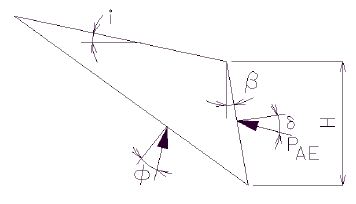
Group Loads
For SPC A and B (if wall does not support an abutment), apply AASHTO Group I Loads only. Bearing capacity, stability and sliding shall be calculated using working stress loads. Reinforced concrete design shall be calculated using load factor design loads.
| Additional Information |
| AASHTO Table 3.22.1A |
AASHTO Group I Load Factors for Load Factor Design of concrete: γ = 1.3
βD = 1.0 for concrete weight
βD = 1.0 for flexural member
βE = 1.3 for lateral earth pressure for retaining walls
βE = 1.0 for vertical earth pressure
βLL = 1.67 for live load wheel lines
βLL = 1.67 for collision forces
| Additional Information |
| AASHTO 5.14.2 |
βE = 1.67 for vertical earth pressure resulting from live load surcharge
βE = 1.3 for horizontal earth pressure resulting from live load surcharge
For SPC B (if wall supports an abutment), C, and D apply AASHTO Group I Loads and seismic loads in accordance with AASHTO Division IA - Seismic Design Specifications.
| Additional Information |
| AASHTO Div. IA 4.7.3 |
When seismic loads are considered, load factor for all loads = 1.0.
751.40.8.15.3 Unit Stresses
Concrete Concrete for retaining walls shall be Class B Concrete (f'c = 3000 psi) unless the footing is used as a riding surface in which case Class B-1 Concrete (f'c = 4000 psi) shall be used.
Reinforcing Steel
Reinforcing Steel shall be Grade 60 (fy = 60,000 psi).
Pile Footing
For steel piling material requirements, see the unit stresses in EPG 751.50 Standard Detailing Notes.
Spread Footing
For foundation material capacity, see Foundation Investigation Geotechnical Report.
751.40.8.15.4 Design
For epoxy coated reinforcement requirements, see EPG 751.5.9.2.2 Epoxy Coated Reinforcement Requirements.
If the height of the wall or fill is a variable dimension, then base the structural design of the wall, toe, and heel on the high quarter point between expansion joints.
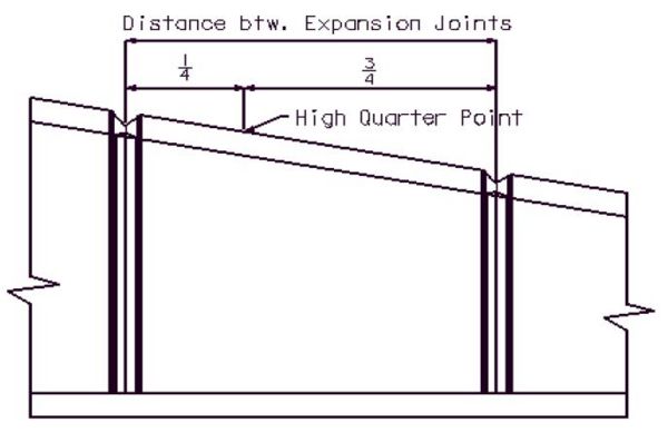
| Additional Information |
| AASHTO 5.5.5 |
751.40.8.15.4.1 Spread Footings
Location of Resultant
The resultant of the footing pressure must be within the section of the footing specified in the following table.
| When Retaining Wall is Built on: | AASHTO Group Loads I-VI | For Seismic Loads |
|---|---|---|
| Soila | Middle 1/3 | Middle 1/2 b |
| Rockc | Middle 1/2 | Middle 2/3 |
| a Soil is defined as clay, clay and boulders, cemented gravel, soft shale, etc. with allowable bearing values less than 6 tons/sq. ft. | ||
| b MoDOT is more conservative than AASHTO in this requirement. | ||
| c Rock is defined as rock or hard shale with allowable bearing values of 6 tons/sq. ft. or more. | ||
Note: The location of the resultant is not critical when considering collision loads.
Factor of Safety Against Overturning
| Additional Information |
| AASHTO 5.5.5 |
AASHTO Group Loads I - VI:
- F.S. for overturning ≥ 2.0 for footings on soil.
- F.S. for overturning ≥ 1.5 for footings on rock.
For seismic loading, F.S. for overturning may be reduced to 75% of the value for AASHTO Group Loads I - VI. For seismic loading:
- F.S. for overturning ≥ (0.75)(2.0) = 1.5 for footings on soil.
- F.S. for overturning ≥ (0.75)(1.5) = 1.125 for footings on rock.
For collision forces:
- F.S. for overturning ≥ 1.2.
Factor of Safety Against Sliding
| Additional Information |
| AASHTO 5.5.5 |
Only spread footings on soil need be checked for sliding because spread footings on rock or shale are embedded into the rock.
- F.S. for sliding ≥ 1.5 for AASHTO Group Loads I - VI.
- F.S. for sliding ≥ (0.75)(1.5) = 1.125 for seismic loads.
- F.S. for sliding ≥ 1.2 for collision forces.
The resistance to sliding may be increased by:
- adding a shear key that projects into the soil below the footing.
- widening the footing to increase the weight and therefore increase the frictional resistance to sliding.
Passive Resistance of Soil to Lateral Load
The Rankine formula for passive pressure can be used to determine the passive resistance of soil to the lateral force on the wall. This passive pressure is developed at shear keys in retaining walls and at end abutments.
| Additional Information |
| AASHTO 5.5.5A |
The passive pressure against the front face of the wall and the footing of a retaining wall is loosely compacted and should be neglected when considering sliding.
Rankine Formula: where thefollowing variables are defined in the figure below
- Cp =
- y1 =
- Pp = passive force at shear key in pounds per foot of wall length
- Cp = coefficient of passive earth pressure
- = unit weight of soil
- H = height of the front face fill less than 1 ft. min. for erosion
- H1 = H minus depth of shear key
- y1 = location of Pp from bottom of footing
- = angle of internal friction of soil
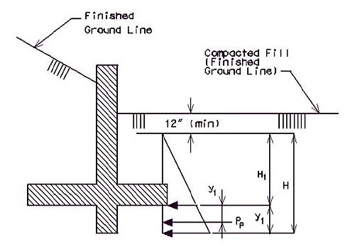
| Additional Information |
| AASHTO 5.5.2 |
The resistance due to passive pressure in front of the shear key shall be neglected unless the key extends below the depth of frost penetration.
| Additional Information |
| MoDOT Materials Division |
Frost line is set at 36 in. at the north border of Missouri and at 18 in. at the south border.
Passive Pressure During Seismic Loading
During an earthquake, the passive resistance of soil to lateral loads is slightly decreased. The Mononobe-Okabe static method is used to determine the equivalent fluid pressure.
- PPE = equivalent passive earth pressure during an earthquake
| Additional Information |
| 1992 AASHTO Div. IA Eqns. C6-5 and C6-6 |
- where:
- KPE = seismic passive pressure coefficient
- = unit weight of soil
- H = height of soil at the location where the earth pressure is to be found
- kV = vertical acceleration coefficient
- = angle of internal friction of soil
- kH = horizontal acceleration coefficient
- = slope of soil face in degrees
- i = backfill slope angle in degrees
- = angle of friction between soil and wall
Special Soil Conditions
Due to creep, some soft clay soils have no passive resistance under a continuing load. Removal of undesirable material and replacement with suitable material such as sand or crushed stone is necessary in such cases. Generally, this condition is indicated by a void ratio above 0.9, an angle of internal friction () less than 22°, or a soil shear less than 0.8 ksf. Soil shear is determined from a standard penetration test.
- Soil Shear
Friction
In the absence of tests, the total shearing resistance to lateral loads between the footing and a soil that derives most of its strength from internal friction may be taken as the normal force times a coefficient of friction. If the plane at which frictional resistance is evaluated is not below the frost line then this resistance must be neglected.
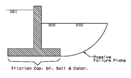
| Additional Information |
| AASHTO 5.5.2B |
Sliding is resisted by the friction force developed at the interface between the soil and the concrete footing along the failure plane. The coefficient of friction for soil against concrete can be taken from the table below. If soil data is not readily available or is inconsistent, the friction factor (f) can be taken as
- f = where is the angle of internal friction of the soil (Civil Engineering Reference Manual by Michael R. Lindeburg, 6th ed., 1992).
| Coefficient of Friction Values for Soil Against Concrete | |
|---|---|
| Soil Typea | Coefficient of Friction |
| coarse-grained soil without silt | 0.55 |
| coarse-grained soil with silt | 0.45 |
| silt (only) | 0.35 |
| clay | 0.30b |
| a It is not necessary to check rock or shale for sliding due to embedment. | |
| b Caution should be used with soils with < 22° or soil shear < 0.8 k/sq.ft. (soft clay soils). Removal and replacement of such soil with suitable material should be considered. | |
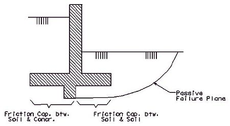
When a shear key is used, the failure plane is located at the bottom of the shear key in the front half of the footing. The friction force resisting sliding in front of the shear key is provided at the interface between the stationary layer of soil and the moving layer of soil, thus the friction angle is the internal angle of friction of the soil (soil against soil). The friction force resisting sliding on the rest of the footing is of that between the concrete and soil. Theoretically the bearing pressure distribution should be used to determine how much normal load exists on each surface, however it is reasonable to assume a constant distribution. Thus the normal load to each surface can be divided out between the two surfaces based on the fractional length of each and the total frictional force will be the sum of the normal load on each surface multiplied by the corresponding friction factor.
Bearing Pressure
| Additional Information |
| AASHTO 4.4.7.1.2 & 4.4.8.1.3 |
- Group Loads I - VI
- The bearing capacity failure factor of safety for Group Loads I - VI must be greater than or equal to 3.0. This factor of safety is figured into the allowable bearing pressure given on the "Design Layout Sheet".
- The bearing pressure on the supporting soil shall not be greater than the allowable bearing pressure given on the "Design Layout Sheet".
- Seismic Loads
| Additional Information |
| AASHTO Div. IA 6.3.1(B) and AASHTO 5.5.6.2 |
- When seismic loads are considered, AASHTO allows the ultimate bearing capacity to be used. The ultimate capacity of the foundation soil can be conservatively estimated as 2.0 times the allowable bearing pressure given on the "Design Layout".
- Stem Design
- The vertical stem (the wall portion) of a cantilever retaining wall shall be designed as a cantilever supported at the base.
- Footing Design
| Additional Information |
| AASHTO 5.5.6.1 |
- Toe
- The toe of the base slab of a cantilever wall shall be designed as a cantilever supported by the wall. The critical section for bending moments shall be taken at the front face of the stem. The critical section for shear shall be taken at a distance d (d = effective depth) from the front face of the stem.
- Heel
- The rear projection (heel) of the base slab shall be designed to support the entire weight of the superimposed materials, unless a more exact method is used. The heel shall be designed as a cantilever supported by the wall. The critical section for bending moments and shear shall be taken at the back face of the stem.
- Shear Key Design
- The shear key shall be designed as a cantilever supported at the bottom of the footing.
751.40.8.15.4.2 Pile Footings
Footings shall be cast on piles when specified on the "Design Layout Sheet". If the horizontal force against the retaining wall cannot otherwise be resisted, some of the piles shall be driven on a batter.
- Pile Arrangement
- For retaining walls subject to moderate horizontal loads (walls 15 to 20 ft. tall), the following layout is suggested.
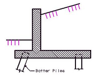
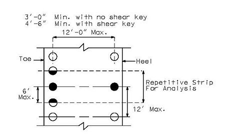
- For higher walls and more extreme conditions of loading, it may be necessary to:
- use the same number of piles along all rows
- use three rows of piles
- provide batter piles in more than one row
- Loading Combinations for Stability and Bearing
- The following table gives the loading combinations to be checked for stability and pile loads. These abbreviations are used in the table:
- DL = dead load weight of the wall elements
- SUR = two feet of live load surcharge
- E = earth weight
- EP = equivalent fluid earth pressure
- COL = collision force
- EQ = earthquake inertial force of failure wedge
| Loading Case | Vertical Loads | Horizontal Loads | Overturning Factor of Safety | Sliding Factor of Safety | |
|---|---|---|---|---|---|
| Battered Toe Piles | Vertical Toe Piles | ||||
| Ia | DL+SUR+E | EP+SUR | 1.5 | 1.5 | 2.0 |
| II | DL+SUR+E | EP+SUR+COL | 1.2 | 1.2 | 1.2 |
| III | DL+E | EP | 1.5 | 1.5 | 2.0 |
| IVb | DL+E | None | - | - | - |
| Vc | DL+E | EP+EQ | 1.125 | 1.125 | 1.5 |
| a Load Case I should be checked with and without the vertical surcharge. | |||||
| b A 25% overstress is allowed on the heel pile in Load Case IV. | |||||
| c The factors of safety for earthquake loading are 75% of that used in Load Case III. Battered piles are not recommended for use in seismic performance categories B, C, and D. Seismic design of retaining walls is not required in SPC A and B. Retaining walls in SPC B located under a bridge abutment shall be designed to AASHTO Specifications for SPC B. | |||||
- Pile Properties and Capacities
- For Load Cases I-IV in the table above, the allowable compressive pile force may be taken from the pile capacity table in the Piling Section of the Bridge Manual which is based in part on AASHTO 4.5.7.3. Alternatively, the allowable compressive pile capacity of a friction pile may be determined from the ultimate frictional and bearing capacity between the soil and pile divided by a safety factor of 3.5 (AASHTO Table 4.5.6.2.A). The maximum amount of tension allowed on a heel pile is 3 tons.
- For Load Case V in the table above, the allowable compressive pile force may be taken from the pile capacity table in the Piling Section of the Bridge Manual multiplied by the appropriate factor (2.0 for steel bearing piles, 1.5 for friction piles). Alternatively, the allowable compressive pile capacity of a friction pile may be determined from the ultimate frictional and bearing capacity between the soil and pile divided by a safety factor of 2.0. The allowable tension force on a bearing or friction pile will be equal to the ultimate friction capacity between the soil and pile divided by a safety factor of 2.0.
- To calculate the ultimate compressive or tensile capacity between the soil and pile requires the boring data which includes the SPT blow counts, the friction angle, the water level, and the soil layer descriptions.
- Assume the vertical load carried by battered piles is the same as it would be if the pile were vertical. The properties of piles may be found in the Piling Section of the Bridge Manual.
- Neutral Axis of Pile Group
- Locate the neutral axis of the pile group in the repetitive strip from the toe of the footing at the bottom of the footing.
- Moment of Inertia of Pile Group
- The moment of inertia of the pile group in the repetitive strip about the neutral axis of the section may be determined using the parallel axis theorem:
- I = Σ(IA) + Σ(Ad2) where :
- IA = moment of inertia of a pile about its neutral axis
- A = area of a pile
- d = distance from a pile's neutral axis to pile group's neutral axis
- IA may be neglected so the equation reduces to:
- I = Σ(Ad2)
- Resistance To Sliding
- Any frictional resistance to sliding shall be ignored, such as would occur between the bottom of the footing and the soil on a spread footing.
- Friction or Bearing Piles With Batter (Case 1)
- Retaining walls using friction or bearing piles with batter should develop lateral strength (resistance to sliding) first from the batter component of the pile and second from the passive pressure against the shear key and the piles.
- Friction or Bearing Piles Without Batter (Case 2)
- Retaining walls using friction or bearing piles without batter due to site constrictions should develop lateral strength first from the passive pressure against the shear key and second from the passive pressure against the pile below the bottom of footing. In this case, the shear key shall be placed at the front face of the footing.
- Concrete Pedestal Piles or Drilled Shafts (Case 3)
- Retaining walls using concrete pedestal piles should develop lateral strength first from passive pressure against the shear key and second from passive pressure against the pile below the bottom of the footing. In this case, the shear key shall be placed at the front of the footing. Do not batter concrete pedestal piles.

- Resistance Due to Passive Pressure Against Pile
- The procedure below may be used to determine the passive pressure resistance developed in the soil against the piles. The procedure assumes that the piles develop a local failure plane.
- F = the lateral force due to passive pressure on pile
- , where:
- = unit weight of soil
- H = depth of pile considered for lateral resistance (Hmax= 6B)
- CP = coefficient of active earth pressure
- B = width of pile
- = angle of internal friction of soil
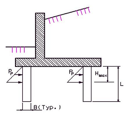
- Resistance Due to Pile Batter
- Use the horizontal component (due to pile batter) of the allowable pile load as the lateral resistance of the battered pile. (This presupposes that sufficient lateral movement of the wall can take place before failure to develop the ultimate strength of both elements.)
- b = the amount of batter per 12 inches.
- (# of battered piles) where:
- PHBatter = the horizontal force due to the battered piles
- PT = the allowable pile load
- Maximum batter is 4" per 12".
- Resistance Due to Shear Keys
- A shear key may be needed if the passive pressure against the piles and the horizontal force due to batter is not sufficient to attain the factor of safety against sliding. The passive pressure against the shear key on a pile footing is found in the same manner as for spread footings.
- Resistance to Overturning
- The resisting and overturning moments shall be computed at the centerline of the toe pile at a distance of 6B (where B is the width of the pile) below the bottom of the footing. A maximum of 3 tons of tension on each heel pile may be assumed to resist overturning. Any effects of passive pressure, either on the shear key or on the piles, which resist overturning, shall be ignored.
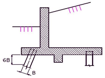
- Pile Properties
- Location of Resultant
- The location of the resultant shall be evaluated at the bottom of the footing and can be determined by the equation below:
- where:
- e = the distance between the resultant and the neutral axis of the pile group
- ΣM = the sum of the moments taken about the neutral axis of the pile group at the bottom of the footing
- ΣV = the sum of the vertical loads used in calculating the moment
- Pile Loads
- The loads on the pile can be determined as follows:
- where:
- P = the force on the pile
- A = the areas of all the piles being considered
- M = the moment of the resultant about the neutral axis
- c = distance from the neutral axis to the centerline of the pile being investigated
- I = the moment of inertia of the pile group
| Additional Information |
| AASHTO 5.5.6.2 |
- Stem Design
- The vertical stem (the wall portion) of a cantilever retaining wall shall be designed as a cantilever supported at the base.
- Footing Design
- Toe
| Additional Information |
| AASHTO 5.5.6.1 |
- The toe of the base slab of a cantilever wall shall be designed as a cantilever supported by the wall. The critical section for bending moments shall be taken at the front face of the stem. The critical section for shear shall be taken at a distance d (d = effective depth) from the front face of the stem.
- Heel
- The top reinforcement in the rear projection (heel) of the base slab shall be designed to support the entire weight of the superimposed materials plus any tension load in the heel piles (neglect compression loads in the pile), unless a more exact method is used. The bottom reinforcement in the heel of the base slab shall be designed to support the maximum compression load in the pile neglecting the weight of the superimposed materials. The heel shall be designed as a cantilever supported by the wall. The critical sections for bending moments and shear shall be taken at the back face of the stem.
- Shear Key Design
- The shear key shall be designed as a cantilever supported at the bottom of the footing.
751.40.8.15.4.3 Counterfort Walls
Assumptions:
(1) Stability The external stability of a counterfort retaining wall shall be determined in the same manner as described for cantilever retaining walls. Therefore refer to previous pages for the criteria for location of resultant, factor of safety for sliding and bearing pressures.
(2) Stem
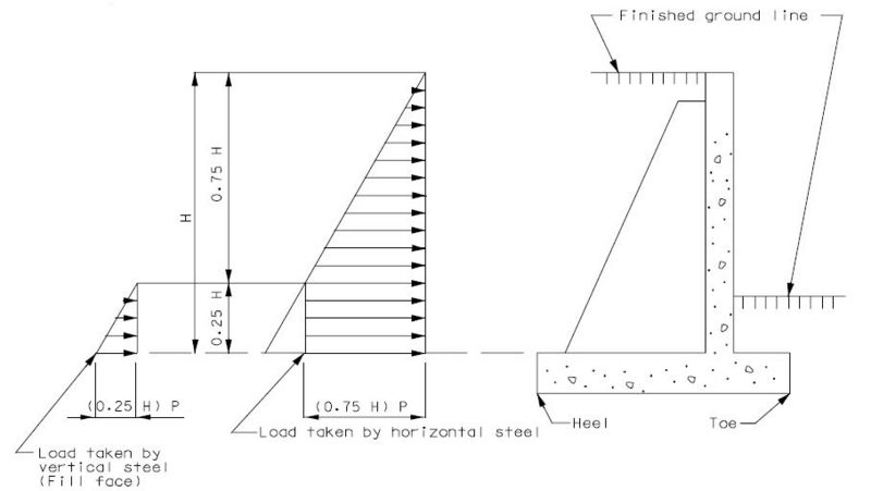
- where:
- Ca = coefficient of active earth pressure
- = unit weigt of soil
Design the wall to support horizontal load from the earth pressure and the liveload surcharge (if applicable) as outlined on the previous pages and as designated in AASHTD Section 3.20, except that maximum horizontal loads shall be the calculated equivalent fluid pressure at 3/4 height of wall [(0.75 H)P] which shall be considered applied uniformly from the lower quarter point to the bottom of wall.
In addition, vertical steel In the fill face of the bottom quarter of the wall shall be that required by the vertical cantilever wall with the equivalent fluid pressure of that (0.25 H) height.
Maximum concrete stress shall be assumed as the greater of the two thus obtained.
The application of these horizontal pressures shall be as follows:

(3) Counterfort Counterforts shall be designed as T-beams, of which the wall is the flange and the counterfort is the stem. For this reason the concrete stresses ane normally low and will not control.
For the design of reinforcing steel in the back of the counterfort, the effective d shall be the perpendicular distance from the front face of the wall (at point that moment is considered), to center of reinforcing steel.
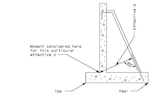
(4) Footing
The footing of the counterfort walls shall be designed as a continuous beam of spans equal to the distance between the counterforts.
The rear projection or heel shall be designed to support the entire weight of the superimposed materials, unless a more exact method is used. Refer to AASHTD Section 5.5.6.
Divide footing (transversely) into four (4) equal sections for design footing pressures.
Counterfort walls on pile are very rare and are to be treated as special cases. See Structural Project Manager.
(5) Sign-Board type walls
The Sign-Board type of retaining walls are a special case of the counterfort retaining walls. This type of wall is used where the soiI conditions are such that the footings must be placed a great distance below the finished ground line. For this situation, the wall is discontinued approximately 12 in. below the finished ground line or below the frost line.
Due to the large depth of the counterforts, it may be more economical to use a smaller number of counterforts than would otherwise be used.
All design assumptions that apply to counterfort walls will apply to sign-board walls with the exception of the application of horizontal forces for the stem (or wall design), and the footing design which shall be as follows:
- Wall
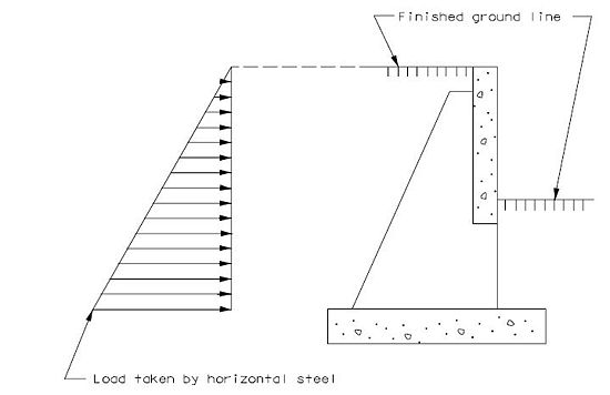
- Footing
- The individual footings shall be designed transversely as cantilevers supported by the wall. Refer to AASHTO Section 5.
751.40.8.15.5 Example 1: Spread Footing Cantilever Wall
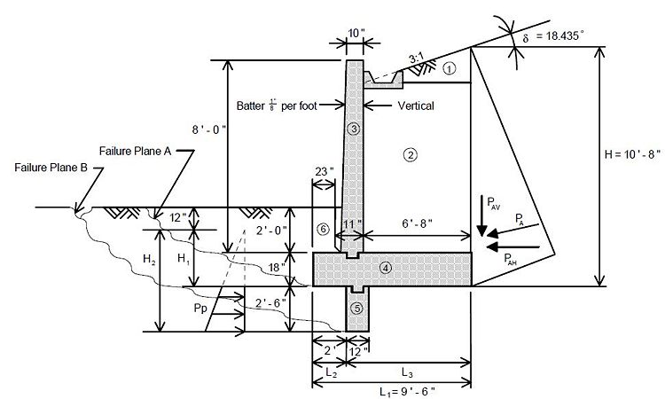
- f'c = 3,000 psi
- fy = 60,000 psi
- φ = 24 in.
- γs = 120 pcf (unit wgt of soil)
- Allowable soil pressure = 2 tsf
- γc = 150 pcf (unit wgt of concr.)
- Retaining wall is located in Seismic Performance Category (SPC) B.
- A = 0.1 (A = seismic acceleration coefficient)
Assumptions
- Retaining wall is under an abutment or in a location where failure of the wall may affect the structural integrity of a bridge. Therefore, it must be designed for SPC B.
- Design is for a unit length (1 ft.) of wall.
- Sum moments about the toe at the bottom of the footing for overturning.
- For Group Loads I-VI loading:
- F.S. for overturning ≥ 2.0 for footings on soil.
- F.S. for sliding ≥ 1.5.
- Resultant to be within middle 1/3 of footing.
- For earthquake loading:
- F.S. for overturning ≥ 0.75(2.0) = 1.5.
- F.S. for sliding ≥ 0.75(1.5) = 1.125.
- Resultant to be within middle 1/2 of footing.
- Base of footing is below the frost line.
- Neglect top one foot of fill over toe when determining passive pressure and soil weight.
- Use of a shear key shifts the failure plane to "B" where resistance to sliding is provided by passive pressure against the shear key, friction of soil along failure plane "B" in front of the key, and friction between soil and concrete along the footing behind the key.
- Soil cohesion along failure plane is neglected.
- Footings are designed as cantilevers supported by the wall.
- Critical sections for bending are at the front and back faces of the wall.
- Critical sections for shear are at the back face of the wall for the heel and at a distance d (effective depth) from the front face for the toe.
- Neglect soil weight above toe of footing in design of the toe.
- The wall is designed as a cantilever supported by the footing.
- Load factors for AASHTO Groups I - VI for design of concrete:
- γ = 1.3.
- βE = 1.3 for horizontal earth pressure on retaining walls.
- βE = 1.0 for vertical earth pressure.
- Load factor for earthquake loads = 1.0.
Lateral Pressures Without Earthquake
- Ca =
- Ca = = 0.546
| Load | Area (ft2) | Force (k) = (Unit Wgt.)(Area) | Arm (ft.) | Moment (ft-k) |
|---|---|---|---|---|
| (1) | (0.5)(6.667ft)(2.222ft) = 7.407 | 0.889 | 7.278 | 6.469 |
| (2) | (6.667ft)(6.944ft) = 46.296 | 5.556 | 6.167 | 34.259 |
| (3) | (0.833ft)(8.000ft) + (0.5)(0.083ft)(8.000ft) = 7.000 | 1.050 | 2.396 | 2.515 |
| (4) | (1.500ft)(9.500ft) = 14.250 | 2.138 | 4.750 | 10.153 |
| (5) | (2.500ft)(1.000ft) = 2.500 | 0.375 | 2.500 | 0.938 |
| (6) | (1.000ft)(1.917ft)+(0.5)(0.010ft)(1.000ft) = 1.922 | 0.231 | 0.961 | 0.222 |
| Σ | - | ΣV = 10.239 | - | ΣMR = 54.556 |
| PAV | - | 1.178 | 9.500 | 11.192 |
| Σ resisting | - | ΣV = 11.417 | - | ΣMR = 65.748 |
| PAH | - | 3.534 | 3.556 | 12.567 |
| PP | - | 2.668 | 1.3891 | - |
| 1 The passive capacity at the shear key is ignored in overturning checks,since this capacity is considered in the factor of safety against sliding. It is assumed that a sliding and overturning failure will not occur simultaneously. The passive capacity at the shear key is developed only if the wall does slide. | ||||
= 1.389 ft.
- Overturning
- F.S. = o.k.
- where: MOT = overturning moment; MR = resisting moment
- Resultant Eccentricity
- = 4.658 ft.
- o.k.
- Sliding
- Check if shear key is required for Group Loads I-VI:
- F.S. = = 0.896 no good - shear key req'd
- where: φs-c = angle of friction between soil and concrete = (2/3)φs-s
- F.S. =
- where: φs-s = angle of internal friction of soil
- F.S. = = 1.789 ≥ 1.5 o.k.
- Footing Pressure
- PH = pressure at heel = 1.132 k/ft2
- PT = pressure at toe = 1.272 k/ft2
- Allowable pressure = 2 tons/ft2 = 4 k/ft2 ≥ 1.272 k/ft2 o.k.
Lateral Pressures With Earthquake
kh = 0.5A = 0.5 (0.1) = 0.05
kv = 0
- Active Pressure on Psuedo-Wall
- δ = φ = 24° (δ is the angle of friction between the soil and the wall. In this case, δ = φ = because the soil wedge considered is next to the soil above the footing.)
- i = 18.435°
- β = 0°
- KAE = 0.674
- PAE = ½γsH2(1 − kv)KAE
- PAE = ½[0.120 k/ft3](10.667 ft)2(1 ft.)(1 - 0)(0.674) = 4.602k
- PAEV = PAE(sinδ) = 4.602k(sin24°) = 1.872k
- PAEH = PAE(cosδ) = 4.602k(cos 24°) = 4.204k
- P'AH = PAEH − PAH = 4.204k − 3.534k = 0.670k
- P'AV = PAEV − PAV = 1.872k − 1.178k = 0.694k
- where: P'AH and P'AV are the seismic components of the active force.
- Passive Pressure on Shear Key
- δ = φ = 24° (δ = φ because the soil wedge considered is assumed to form in front of the footing.)
- i = 0
- β = 0
- KPE = 0.976
- PPE = ½γsH2(1 − kv)KPE
- PPE = ½[0.120 k/ft3][(5.0 ft)2 - (2.5 ft2)](1 ft.)(1 - 0)(0.976) = 1.098k
| Load | Force (k) | Arm (ft) | Moment (ft-k) |
|---|---|---|---|
| Σ (1) thru (6) | 10.239 | - | 54.556 |
| PAV | 1.178 | 9.500 | 11.192 |
| P'AV | 0.694 | 9.500 | 6.593 |
| Σresisting | ΣV = 12.111 | - | ΣMR = 72.341 |
| PAH | 3.534 | 3.556 | 12.567 |
| P'AH | 0.670 | 6.400a | 4.288 |
| PPEV | 0.447b | 0.000 | 0.000 |
| PPEH | 1.003b | 1.389c | 0.000 |
| - | - | - | ΣMOT = 16.855 |
| a P'AH acts at 0.6H of the wedge face (1992 AASHTO Div. IA Commentary). | |||
| b PPEH and PPEH are the components of PPE with respect to δ (the friction angle). PPE does not contribute to overturning. | |||
| c The line of action of PPEH can be located as was done for PP. | |||
- Overturning
- o.k.
- Resultant Eccentricity
- o.k.
- Sliding
- o.k.
- Footing Pressure
- for e ≤ L/6:
- = 1.139 k/ft2
- = 1.411 k/ft2
- Allowable soil pressure for earthquake = 2 (allowable soil pressure)
- (2)[4 k/ft2] = 8 k/ft2 > 1.411 k/ft2 o.k.
Reinforcement-Stem
d = 11" - 2" - (1/2)(0.5") = 8.75"
b = 12"
f'c = 3,000 psi
- Without Earthquake
- PAH = ½ [0.120 k/ft3](0.546)(6.944 ft.)2(1 ft.)(cos 18.435°) = 1.499k
- γ = 1.3
- βE = 1.3 (active lateral earth pressure)
- Mu = (1.3)(1.3)(1.499k)(2.315ft) = 5.865 (ft-k)
- With Earthquake
- kh = 0.05
- kv = 0
| Additional Information |
| 1992 AASHTO Div. IA Commentary |
- θ = 2.862°
- δ = φ/2 = 24°/2 = 12° for angle of friction between soil and wall. This criteria is used only for seismic loading if the angle of friction is not known.
- φ = 24°
- i = 18.435°
- β = 0°
- KAE = 0.654
- PAEH = 1/2 γsKAEH2cosδ
- PAEH = 1/2 [0.120k/ft](0.654)(6.944 ft.)2(1 ft.) cos(12°) = 1.851k
- Mu = (1.499k)(2.315 ft.) + (1.851k − 1.499k)(0.6(6.944 ft.)) = 4.936(ft−k)
- The moment without earthquake controls:
- = 85.116 psi
- ρ =
- ρ = = 0.00144
| Additional Information |
| AASHTO 8.17.1.1 & 8.15.2.1.1 |
- ρmin = = 0.00245
- Use ρ = 4/3 ρ = 4/3 (0.00144) = 0.00192
- ASReq = ρbd = 0.00192 (12 in.)(8.75 in.) = 0.202 in.2/ft
- One #4 bar has AS = 0.196 in2
- s = 11.64 in.
- Use #4's @ 10" cts.
- Check Shear
- Vu ≥ φ Vn
- Without Earthquake
- Vu, = (1.3)(1.3)(1.499k) = 2.533k
- With Earthquake
- Vu = 1.851k
- The shear force without earthquake controls.
- = 28.4 psi
- = 109.5 psi > 28.4 psi o.k.
Reinforcement-Footing-Heel
Note: Earthquake will not control and will not be checked.
βE = 1.0 (vertical earth pressure)
d = 18" - 3" - (1/2)(0.750") = 14.625"
b = 12"
f'c = 3,000 psi
Mu = 1.3 [(5.556k + 1.500k)(3.333ft) + 0.889k(4.444ft) + 1.178k(6.667ft)]
Mu = 45.919(ft−k)
= 238.5 psi
ρ = = 0.00418
ρmin = = 0.00235
ASReq = 0.00418 (12 in.) (14.625 in.) = 0.734 in2/ft.
Use #6's @ 7" cts.
- Check Shear
- Shear shall be checked at back face of stem.
- Vu = 1.3 (5.556k + 1.500k + 0.889k + 1.178k) = 11.860k
- = 109.5 psi o.k.
Reinforcement-Footing-Toe
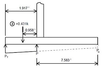
d = 18" - 4" = 14"
b = 12"
- Without Earthquake
- Apply Load Factors
- load 4 (weight) = 0.431k(1.3)(1.0) = 0.560k
- βE = 1.3 for lateral earth pressure for retaining walls.
- βE = 1.0 for vertical earth pressure.
- ΣMOT = 12.567(ft−k)(1.3)(1.3) = 21.238(ft−k)
- ΣMR = [54.556(ft−k) + 11.192(ft−k)](1.3)(1.0) = 85.472(ft−k)
- ΣV = 11.417k(1.3)(1.0) = 14.842k
- = 4.328 ft.
- e = (9.5 ft./2) − 4.328 ft. = 0.422 ft.
- = 1.146k/ft2
- = 1.979k/ft2
- = 1.811k/ft.
- Mu = 2.997(ft−k)
- With Earthquake
- PH = 1.139 k/ft
- PT = 1.411 k/ft
- = 1.356 k/ft
- Mu = 2.146(ft−k)
- The moment without earthquake controls.
- = 16.990 psi
- ρ = = 0.000284
- ρmin = = 0.00257
- Use ρ = 4/3 ρ = = 0.000379
- ASReq = 0.000379 (12 in.)(14.0 in.) = 0.064 in.2/ft.
- s = 36.8 in.
- Minimum is # 4 bars at 12 inches. These will be the same bars that are in the back of the stem. Use the smaller of the two spacings.
- Use # 4's @ 10" cts.
- Check Shear
- Shear shall be checked at a distance "d" from the face of the stem.
- Without Earthquake
- = 1.913k/ft.
- = 1.240k
- With Earthquake
- = 1390k/ft.
- = 0.788k
- Shear without earthquake controls.
- = 109.5 psi o.k.
Reinforcement-Shear Key
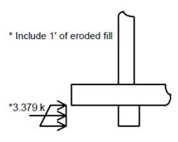
The passive pressure is higher without earthquake loads.
γ = 1.3
βE = 1.3 (lateral earth pressure)
d = 12"-3"-(1/2)(0.5") = 8.75"
b = 12"
Mu = (3.379k)(1.360 ft.)(1.3)(1.3) = 7.764(ft−k)
= 112.677 psi
ρ = = 0.00192
ρmin = = 0.00292
Use ρ = 4/3 ρ = 4/3 (0.00192) = 0.00256
ASReq = 0.00256(12 in.)(8.75 in.) = 0.269 in.2/ft.
Use # 4 @ 8.5 in cts.
Check Shear
- = 109.5 psi o.k.
Reinforcement Summary
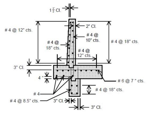
751.40.8.15.6 Example 2: L-Shaped Cantilever Wall
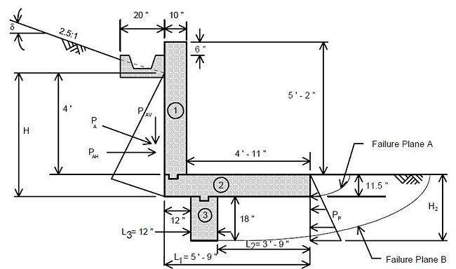
f'c = 4000 psi
fy = 60,000 psi
φ = 29°
γs = 120 pcf
Allowable soil pressure = 1.5 tsf = 3.0 ksf
Retaining wall is located in Seismic Performance Category (SPC) A.
= 21.801°
= 0.462
= 2.882
PA = 1/2 γs CaH2 = 1/2 (0.120 k/ft3)(0.462)(4.958 ft.)2 = 0.681k
For sliding, PP is assumed to act only on the portion of key below the frost line that is set at an 18 in. depth on the southern border.
PP = 1/2 (0.120 k/ft3)(2.882)[(2.458 ft.)2 − (1.500 ft.)2] = 0.656k
Assumptions
- Design is for a unit length (1 ft.) of wall.
- Sum moments about the toe at the bottom of the footing for overturning.
- F.S. for overturning ≥ 2.0 for footings on soil.
- F.S. for sliding ≥ 1.5 for footings on soil.
- Resultant of dead load and earth pressure to be in back half of the middle third of the footing if subjected to frost heave.
- For all loading combinations the resultant must be in the middle third of the footing except for collision loads.
- The top 12 in. of the soil is not neglected in determining the passive pressure because the soil there will be maintained.
- Frost line is set at 18 in. at the south border for Missouri.
- Portions of shear key which are above the frost line are assumed not to resist sliding by passive pressure.
- Use of a shear key shifts the failure plane to "B" where resistance to sliding is also provided by friction of soil along the failure plane in front of the shear key. Friction between the soil and concrete behind the shear key will be neglected.
- Soil cohesion along the failure plane is neglected.
- Live loads can move to within 1 ft. of the stem face and 1 ft. from the toe.
- The wall is designed as a cantilever supported by the footing.
- Footing is designed as a cantilever supported by the wall. Critical sections for bending and shear will be taken at the face of the wall.
- Load factors for AASHTO Groups I-VI for design of concrete are:
- γ = 1.3.
- βE = 1.3 for horizontal earth pressure on retaining walls.
- βE = 1.0 for vertical earth pressure.
- βLL = 1.67 for live loads and collision loads.
Dead Load and Earth Pressure - Stabilty and Pressure Checks
| Dead Load and Earth Pressure - Stabilty and Pressure Checks | |||
|---|---|---|---|
| Load | Force (k) | Arm (in.) | Moment (ft-k) |
| (1) | (0.833 ft.)(5.167 ft.)(0.150k/ft3) = 0.646 | 5.333 | 3.444 |
| (2) | (0.958ft)(5.750ft)(0.150k/ft3) = 0.827 | 2.875 | 2.376 |
| (3) | (1.000ft)(1.500ft)(0.150k/ft3) = 0.22534.259 | 4.250 | 0.956 |
| ΣV = 1.698 | ΣMR = 6.776 | ||
| PAV | 0.253 | 5.750 | 1.455 |
| ΣV = 1.951 | ΣMR = 8.231 | ||
| PAH | 0.633 | 1.653 | 1.045 |
| PP | 0.656 | 1.061 | - |
| ΣMOT = 1.045 | |||
| 1 The passive pressure at the shear key is ignored in overturning checks. | |||
- Overturning
- = 7.877 ≥ 2.0 o.k.
- Location of Resultant
- MoDOT policy is that the resultant must be in the back half of the middle third of the footing when considering dead and earth loads:
- = 3.683 ft. o.k.
- Sliding
- where:
- φs-s = angle of internal friction of soil
- φs-c = angle of friction between soil and concrete = (2/3)φs-s
- = 2.339 ≥ 1.5 o.k.
- Footing Pressure
- = 0.808 ft.
- Heel: = 0.625 ksf < 3.0 ksf o.k.
- Toe: = 0.053 ksf < 3.0 ksf o.k.
Dead Load, Earth Pressure, and Live Load - Stability and Pressure Checks
Stability is not an issue because the live load resists overturning and increases the sliding friction force.
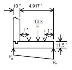
The live load will be distributed as:
- where E = 0.8X + 3.75
- X = distance in feet from the load to the front face of wall
The live load will be positioned as shown by the dashed lines above. The bearing pressure and resultant location will be determined for these two positions.
- Live Load 1 ft From Stem Face
- Resultant Eccentricity
- X = 1 ft.
- E = 0.8(1 ft.) + 3.75 = 4.55 ft.
- = 3.516k
- = 3.834 ft.
- = 5.75 ft. o.k.
- Footing Pressure
- Allowable Pressure = 3.0 ksf
- Heel: = 1.902 ksf
- Toe: = 0.000ksf
- Live Load 1 ft From Toe
- Resultant Eccentricity
- X = 3.917 ft.
- E = 0.8(3.917 ft.) + 3.75 = 6.883 ft.
- = 2.324k
- = 2.225 ft.
- = 0.958 ft. o.k.
- Footing Pressure
- Allowable Pressure = 3.0ksf
- Heel: = 0.239ksf o.k.
- Toe: = 1.248ksf o.k.
Dead Load, Earth Pressure, Collision Load, and Live Load - Stability and Pressure Checks
During a collision, the live load will be close to the wall so check this combination when the live load is one foot from the face of the stem. Sliding (in either direction) will not be an issue. Stability about the heel should be checked although it is unlikely to be a problem. There are no criteria for the location of the resultant, so long as the footing pressure does not exceed 125% of the allowable. It is assumed that the distributed collision force will develop an equal and opposite force on the fillface of the back wall unless it exceeds the passive pressure that can be developed by soil behind the wall.
FLL = 3.516k
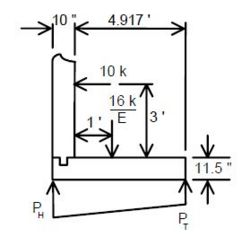
FCOLL = = 1.667k
= 1.867
PPH = 2.556k > FCOLL Thus the soil will develop an equal but opp. force.
- Overturning About the Heel
- F.S. =
- F.S. = = 1.847 ≥ 1.2 o.k.
- Footing Pressure
- = 1.022 ft. from heel
- e = = 1.853 ft.
- Allowable Pressure = (1.25)(3.0ksf) = 3.75ksf
- Heel: = 3.566ksf o.k.
Stem Design-Steel in Rear Face
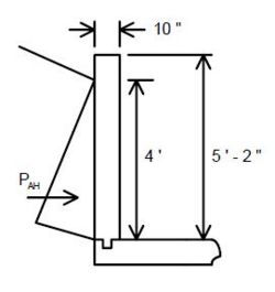
γ = 1.3
βE = 1.3 (active lateral earth pressure)
d = 10 in. − 2 in. − (0.5 in./2) = 7.75 in.
PAH = 0.412k
Mu = (1.333 ft.)(0.412k)(1.3)(1.3) = 0.928(ft−k)
= 17.160psi
= 0.000287
= 0.00298
Use ρ = (4/3)ρ = (4/3)(0.000287) = 0.000382
One #4 bar has AS = 0.196 in2, so the required minimum of one #4 bar every 12 in. controls.
Use #4's @ 12 in. (min)
(These bars are also the bars in the bottom of the footing so the smaller of the two required spacings will be used.)
- Check Shear
- = 8.8 psi
- = 126.5 psi > 8.8 psi o.k.
Stem Design-Steel in Front Face (Collision Loads)
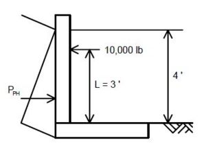
The soil pressure on the back of the stem becomes passive soil pressure during a collision, however this pressure is ignored for reinforcement design.
γ = 1.3
βLL = 1.67
= 7.75 in.
= 1.667 k/ft.
Mu = 1.667k/ft. (1 ft.)(3 ft.)(1.3)(1.67) = 10.855(ft−k)
= 200.809 psi
= 0.00345
= 0.00298
One #4 bar has AS = 0.196 in2.
s = 7.3 in.
Use #4's @ 7 in.
- Check Shear
- = 45.8 psi < 126.5 psi o.k.
Footing Design - Bottom Steel
It is not considered necessary to design footing reinforcement based upon a load case which includes collision loads.
- Dead Load and Earth Pressure Only
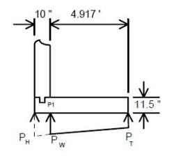
- Footing wt. = = 0.707k
- βE = 1.3 (lateral earth pressure)
- γ = 1.3
- Apply Load Factors:
- ΣV = 1.951k (1.3) = 2.536k
- ΣMR = 8.231(ft−k)(1.3) = 10.700(ft−k)
- ΣMOT = 1.045(ft−k)(1.3)(1.3) = 1.766(ft−k)
- Footing wt. = 0.707k (1.3) = 0.919k
- = 3.523 ft.
- = 0.648 ft.
- = 0.739 ksf
- = 0.143ksf
- = 0.653 ksf
- Moment at Wall Face:
- = 1.524(ft−k)
- Dead Load, Earth Pressure, and Live Load
- Live Load 1 ft. From Stem Face
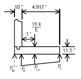
- βE = 1.3 (lateral earth pressure)
- βLL = 1.67
- γ = 1.3
- Apply Load Factors:
- FLL = 3.516k(1.3)(1.67) = 7.633k
- ΣV = 7.633k + 1.951k(1.3) = 10.169k
- ΣMOT = 1.045(ft−k)(1.3)(1.3) = 1.766(ft−k)
- ΣMR = 8.231(ft−k)(1.3) + 3.917 ft.(7.633k) = 40.599(ft−k)
- = 3.819 ft.
- e = 3.819 ft. − (5.75 ft./2) = 0.944 ft.
- = 0.026 ksf
- = 3.511 ksf
- = 3.006 ksf
- = 2.400 ksf
- Footing wt. from face of wall to toe:
- Footing wt. = = 0.919k
- Footing wt. from LLWL to toe:
- Footing wt. = = 0.732k
- Moment at Wall Face:
- MW =
- MW = 2.430(ft−k)
- Moment at LLWL:
- MLL = = 4.837(ft−k)
- Live Load 1 ft. From Toe
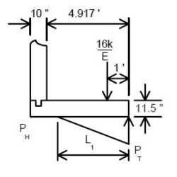
- Apply Load Factors:
- FLL = 2.324k(1.3)(1.67) = 5.045k
- ΣV = 5.045k + 1.951k(1.3) = 7.581k
- ΣMOT = 1.045(ft−k)(1.3)(1.3) = 1.766(ft−k)
- ΣMR = 8.231(ft−k)(1.3) + 5.045k(1ft.) = 15.745(ft−k)
- = 1.844 ft.
- = 1.031 ft.
- PH = 0 ksf
- = 2.741 ksf
- L1 = 3[(L/2)− e]
- L1 = 3[(5.75 ft./2)− 1.031 ft.] = 5.532 ft.
- = 0.305 ksf
- = 2.196 ksf
- Moment at Wall Face:
- MW = = 1.298(ft−k)
- Moment at LLWL:
- MLL = = 1.186(ft−k)
- Design Flexural Steel in Bottom of Footing
- d = 11.5 in. − 4 in. = 7.500 in.
- Mu = 4.837(ft−k) (controlling moment)
- = 0.096 ksi
- = 0.00162
- = 0.00421
- Use ρ = (4/3)ρ = (4/3)(0.00162) = 0.00216
- ASReq = 0.00216(12 in.)(7.5 in.) = 0.194 in2/ft.
- s = 12.1 in.
- Use #4's @ 12 in. cts. (Also use this spacing in the back of the stem.)
- Check Shear
- Dead Load and Earth Pressure Only
- VW = 1.038k
- Live Load 1 ft. From Stem Face
- Shear at the wall can be neglected for this loading case.
- VLL = 4.019k
- Live Load 1 ft. From Toe
- VW = 1.525k
- VLL = 2.282k
- Use VU = 4.019k
- = 126.5 psi
Shear Key Design
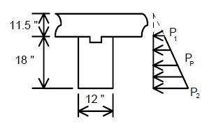
For concrete cast against and permanently exposed to earth, minimum cover for reinforcement is 3 inches.
= 8.75 in.
= 0.331 k/ft.
= 0.850 k/ft.
Mu = 1.287(ft−k)
= 0.0187 ksi
= 0.000312
= 0.00337
Use ρ = (4/3)ρ = (4/3)(0.000312) = 0.000416
ASReq = 0.000416 (12 in.)(8.75 in.) = 0.0437 in2/ft.
s = 53.8 in.
Use #4's @ 18 in. cts. (min)
- Check Shear
- V = 0.886k
- = 16.8 psi < 126.5 psi o.k.
Reinforcement Summary
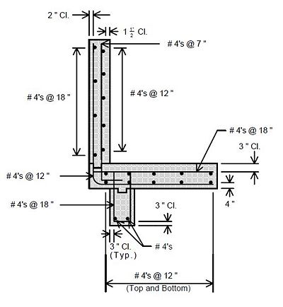
751.40.8.15.7 Example 3: Pile Footing Cantilever Wall
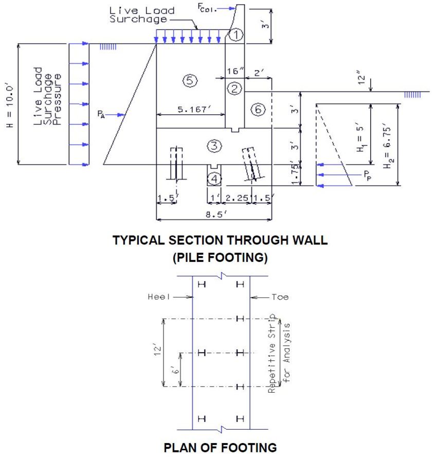
f’c = 3,000 psi
fy = 60,000 psi
φ = 27°
γs = 120 pcf
Pile type: HP 10 x 42
Allowable pile bearing = 56 tons
Pile width = 10 inches
Toe pile batter = 1:3
See EPG 751.12 Barriers, Railings, Curbs and Fences for weight and centroid of barrier.
Assumptions
- Retaining wall is located such that traffic can come within half of the wall height to the plane where earth pressure is applied.
- Reinforcement design is for one foot of wall length.
- Sum moments about the centerline of the toe pile at a distance of 6B (where B is the pile width) below the bottom of the footing for overturning.
- Neglect top one foot of fill over toe in determining soil weight and passive pressure on shear key.
- Neglect all fill over toe in designing stem reinforcement.
- The wall is designed as a cantilever supported by the footing.
- Footing is designed as a cantilever supported by the wall.
- Critical sections for bending are at the front and back faces of the wall.
- Critical sections for shear are at the back face of the wall for the heel and at a distance d (effective depth) from the front face for the toe.
- For load factors for design of concrete, see EPG 751.24.1.2 Group Loads.
δ = 0, ϕ = 27° so CA reduces to:
= 0.376
= 2.663
Table 751.24.3.5.1 is for stability check (moments taken about C.L. of toe pile at a depth of 6B below the bottom of the footing).
| Load | Force (kips/ft) | Arm about C.L. of toe pile at 6B below footing (ft.) | Moment (ft-kips) per foot of wall length | |
|---|---|---|---|---|
| Dead Load | (1) | 0.340 | 2.542 | 0.864 |
| (2) | (1.333 ft.)(7.000 ft.)(0.150k/ft3) = 1.400 | 2.833 | 3.966 | |
| (3) | (3.000 ft.)(8.500 ft.)(0.150k/ft3) = 3.825 | 4.417 | 16.895 | |
| (4) | (1.000 ft.)(1.750 ft.)(0.150k/ft3) = 0.263 | 4.417 | 1.162 | |
| Σ | ΣV = 5.828 | - | ΣMR = 22.887 | |
| Earth Load | (5) | (7.000 ft.)(5.167 ft.)(0.120k/ft3) = 4.340 | 6.083 | 26.400 |
| (6) | (2.000 ft.)(2.000 ft.)(0.120k/ft3) = 0.480 | 1.167 | 0.560 | |
| Σ | ΣV = 4.820 | - | ΣMR = 26.960 | |
| Live Load Surcharge | PSV | (2.000 ft.)(5.167 ft.)(0.120k/ft3) = 1.240 | 6.083 | MR = 7.543 |
| PSH | (2.000 ft.)(0.376)(10.000 ft.)(0.120k/ft3) = 0.902 | 10.000 | MOT = 9.020 | |
| Earth Pressure | PA | 2.2561 | 8.333 | MOT = 18.799 |
| PP | 3.2852 | - | - | |
| Collision Force (FCOL) | (10.000k)/[2(7.000 ft.)] = 0.714 | 18.000 | MOT = 12.852 | |
| Heel Pile Tension (PHV) | (3.000 tons)(2 k/ton)(1 pile)/(12.000 ft.) = 0.500 | 7.167 | MR = 3.584 | |
| Toe Pile Batter (PBH) | 5.9033 | - | - | |
| Passive Pile Pressure (Ppp) | 0.8324 | - | - | |
| 1 | ||||
| 2 | ||||
| 3 | ||||
| 4 | ||||
Table 751.24.3.5.2 is for bearing pressure checks (moments taken about C.L of toe pile at the bottom of the footing).
| Load | Force (kips/ft) | Arm about C.L. of toe pile at 6B below footing (ft.) | Moment (ft-kips) per foot of wall length | |
|---|---|---|---|---|
| Dead Load | (1) | 0.340 | 0.875 | 0.298 |
| (2) | (1.333 ft.)(7.000 ft.)(0.150k/ft3) = 1.400 | 1.167 | 1.634 | |
| (3) | (3.000 ft.)(8.500 ft.)(0.150k/ft3) = 3.825 | 2.750 | 10.519 | |
| (4) | (1.000 ft.)(1.750 ft.)(0.150k/ft3) = 0.263 | 2.750 | 0.723 | |
| Σ | ΣV = 5.828 | - | ΣMR = 13.174 | |
| Earth Load | (5) | (7.000 ft.)(5.167 ft.)(0.120k/ft3) = 4.340 | 4.417 | 19.170 |
| (6) | (2.000 ft.)(2.000 ft.)(0.120k/ft3) = 0.480 | -0.500 | -0.240 | |
| Σ | ΣV = 4.820 | - | ΣMR = 18.930 | |
| Live Load Surcharge | PSV | (2.000 ft.)(5.167 ft.)(0.120k/ft3) = 1.240 | 4.417 | MR = 5.477 |
| PSH | (2.000 ft.)(0.376)(10.000 ft.)(0.120k/ft3) = 0.902 | 5.000 | MOT = 4.510 | |
| Earth Pressure | PA | 2.256 | 3.333 | MOT = 7.519 |
| PP | 3.285 | - | - | |
| Collision Force (FCOL) | (10.000k)/[2(7.000 ft.)] = 0.714 | 13.000 | MOT = 9.282 | |
| Heel Pile Tension (PHV) | (3.000 tons)(2 k/ton)(1 pile)/(12.000 ft.) = 0.500 | 5.500 | MR = 2.750 | |
| Toe Pile Batter (PBH) | 5.903 | - | - | |
| Passive Pile Pressure (Ppp) | 0.832 | - | - | |
Investigate a representative 12 ft. strip. This will include one heel pile and two toe piles. The assumption is made that the stiffness of a batter pile in the vertical direction is the same as that of a vertical pile.
Neutral Axis Location = [2piles(1.5 ft.) + 1pile(7 ft.)] / (3 piles) = 3.333 ft. from the toe.
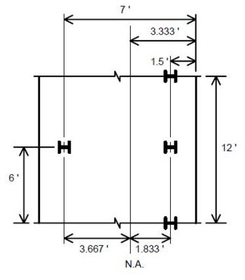
I = Ad2
For repetitive 12 ft. strip:
- Total pile area = 3A
- I = 2A(1.833 ft.)2 + A(3.667 ft.)2 = 20.167(A)ft.2
For a 1 ft. unit strip:
- Total pile area = (3A/12 ft.) = 0.250A
- Case I
- F.S. for overturning ≥ 1.5
- F.S. for sliding ≥ 1.5
- Check Overturning
- Neglect resisting moment due to PSV for this check.
- ΣMR = 22.887(ft−k) + 26.960(ft−k) + 3.584(ft−k)
- ΣMR = 53.431(ft−k)
- ΣMOT = 9.020(ft−k) + 18.799(ft−k) = 27.819(ft−k)
- F.S.OT = = 1.921 > 1.5 o.k.
- Check Pile Bearing
- Without PSV :
- ΣV = 5.828k + 4.820k = 10.648k
- e = = 1.885 ft.
- Moment arm = 1.885 ft. - 1.833 ft. = 0.052 ft.
- Allowable pile load = 56 tons/pile. Each pile has area A, so:
- o.k.
- o.k.
- With PSV:
- ΣV = 5.828k + 4.820k + 1.240k = 11.888k
- = 2.149 ft.
- Moment arm = 2.149 ft. - 1.833 ft. = 0.316 ft.
- o.k.
- o.k.
- Check Sliding
- = 3.173 ≥ 1.5 o.k.
- Case II
- F.S. for overturning ≥ 1.2
- F.S. for sliding ≥ 1.2
- Check Overturning
- ΣMR = (22.887 + 26.960 + 7.543 + 3.584)(ft−k) = 60.974(ft−k)
- ΣMOT = (9.020 + 18.799 + 12.852)(ft−k) = 40.671(ft−k)
- = 1.499 ≥ 1.2 o.k.
- Check Pile Bearing
- = 1.369 ft.
- Moment arm = 1.833 ft. - 1.369 ft. = 0.464 ft.
- o.k.
- = 35.519k
- o.k.
- Check Sliding
- = 2.588 ≥ 1.2 o.k.
- Case III
- F.S. for overturning ≥ 1.5
- F.S. for sliding ≥ 1.5
- Check Overturning
- ΣMR = (22.887 + 26.960 + 3.584)(ft−k) = 53.431(ft−k)
- ΣMOT = 18.799(ft−k)
- = 2.842 ≥ 1.5 o.k.
- Check Pile Bearing
- = 2.309 ft.
- Moment arm = 2.309 ft. - 1.833 ft. = 0.476 ft.
- = 37.065k
- o.k.
- = 53.649k
- o.k.
- Check Sliding
- = 4.441 ≥ 1.5 o.k.
- Case IV
- Check Pile Bearing
- = 3.015 ft.
- Moment arm = 3.015 ft. - 1.833 ft. = 1.182 ft.
- 25% overstress is allowed on the heel pile:
- o.k.
- = 28.868k
- o.k.
- Reinforcement - Stem
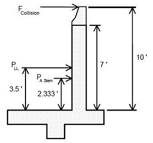
- b = 12 in.
- cover = 2 in.
- h = 16 in.
- d = 16 in. - 2 in. - 0.5(0.625 in.) = 13.688 in.
- FCollision = 0.714k/ft
- Apply Load Factors
- FCol. = γβLL(0.714k) = (1.3)(1.67)(0.714k) = 1.550k
- PLL = γβE (0.632k) = (1.3)(1.67)(0.632k) = 1.372k
- PAStem = γβE (1.105k) = (1.3)(1.3)(1.105k) = 1.867k
- Mu = (10.00 ft.)(1.550k) + (3.500 ft.)(1.372k) + (2.333 ft.)(1.867k)
- Mu = 24.658(ft−k)
- = 0.146ksi
- = 0.00251
- = 0.00212
- ρ = 0.00251
- One #5 bar has AS = 0.307 in2
- s = 8.9 in.
- Use # 5 bars @ 8.5 in. cts.
- Check Shear
- Vu ≤ φVn
- Vu = FCollision + PLL + PAStem = 1.550k + 1.372k + 1.867k = 4.789k
- = 34.301 psi
- = 109.5 psi > 34.3 psi o.k.
- Reinforcement - Footing - Top Steel
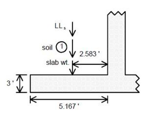
- b = 12 in.
- cover = 3 in.
- h = 36 in.
- d = 36 in. - 3 in. - 0.5(0.5 in.) = 32.750 in.
- Design the heel to support the entire weight of the superimposed materials.
- Soil(1) = 4.340k/ft.
- LLs = 1.240k/ft.
- = 2.325k/ft.
- Apply Load Factors
- Soil(1) = γβE(4.340k) = (1.3)(1.0)(4.340k) = 5.642k
- LLs = γβE(1.240k) = (1.3)(1.67)(1.240k) = 2.692k
- Slab wt. = γβD(2.325k) = (1.3)(1.0)(2.325k) = 3.023k
- Mu = (2.583 ft.)(5.642k + 2.692k + 3.023k) = 29.335(ft−k)
- = 0.0304 ksi
- = 0.000510
- = 0.00188
- Use ρ = 4/3 ρ = 4/3 (0.000510) = 0.000680
- One #4 bar has As = 0.196 in.2
- s = 8.8 in.
- Use #4 bars @ 8.5 in. cts.
- Check Shear
- = 33.998 psi ≤ 109.5 psi = νc o.k.
- Reinforcement - Footing - Bottom Steel
- Design the flexural steel in the bottom of the footing to resist the largest moment that the heel pile could exert on the footing. The largest heel pile bearing force was in Case IV. The heel pile will cause a larger moment about the stem face than the toe pile (even though there are two toe piles for every one heel pile) because it has a much longer moment arm about the stem face.
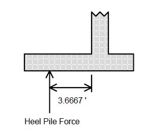
- Pile is embedded into footing 12 inches.
- b = 12 in.
- h = 36 in.
- d = 36 in. - 4 in. = 32 in.
- Apply Load Factors to Case IV Loads
- ΣV = 13.842 k/ft.
- ΣM = 41.735 (ft−k)/ft.
- e = = 3.015 ft.
- Moment arm = 3.015 ft. - 1.833 ft. = 1.182 ft.
- = 7.588 k/ft.
- = 27.825(ft−k)/ft.
- = 0.0301 ksi
- = 0.000505
- = 0.00196
- Use ρ = 4/3 ρ = 4/3 (0.000505) = 0.000673
- ASReq = ρbd = (0.000673)(12 in.)(32 in.) = 0.258 in2/ft.
- One #4 bar has As = 0.196 in2.
- s = 9.1 in.
- Use #4 bars @ 9 in. cts.
- Check Shear
- The critical section for shear for the toe is at a distance d = 21.75 inches from the face of the stem. The toe pile is 6 inches from the stem face so the toe pile shear does not affect the shear at the critical section. The critical section for shear is at the stem face for the heel so all of the force of the heel pile affects the shear at the critical section. The worst case for shear is Case IV.
- Vu = 7.588k
- = 23.248 psi ≤ 109.5 psi = νc o.k.
- Reinforcement - Shear Key
- b = 12 in.
- h = 12 in.
- cover = 3 in.
- d = 12 in. - 3 in. - 0.5(0.5 in.) = 8.75 in.
- Apply Load Factors
- PP = γβE (3.845k) = (1.3)(1.3)(3.845k) = 6.498k
- Mu = (0.912 ft.)(6.498k) = 5.926(ft−k)
- = 0.0860 ksi
- = 0.00146
- = 0.00292
- Use ρ = 4/3 ρ = 4/3(0.00146) = 0.00195
- ASReq = ρbd = (0.00195)(12 in.)(8.75 in.) = 0.205 in.2/ft.
- One #4 bar has As = 0.196 in2
- s = 11.5 in.
- Use #4 bars @ 11 in. cts.
- Check Shear
- = 72.807 psi < 109.5 psi = νc
- Reinforcement Summary
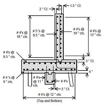
751.40.8.15.8 Dimensions
Cantilever Walls
Each section of wall shall be in increments of 4 ft. with a maximum length of 28'-0".
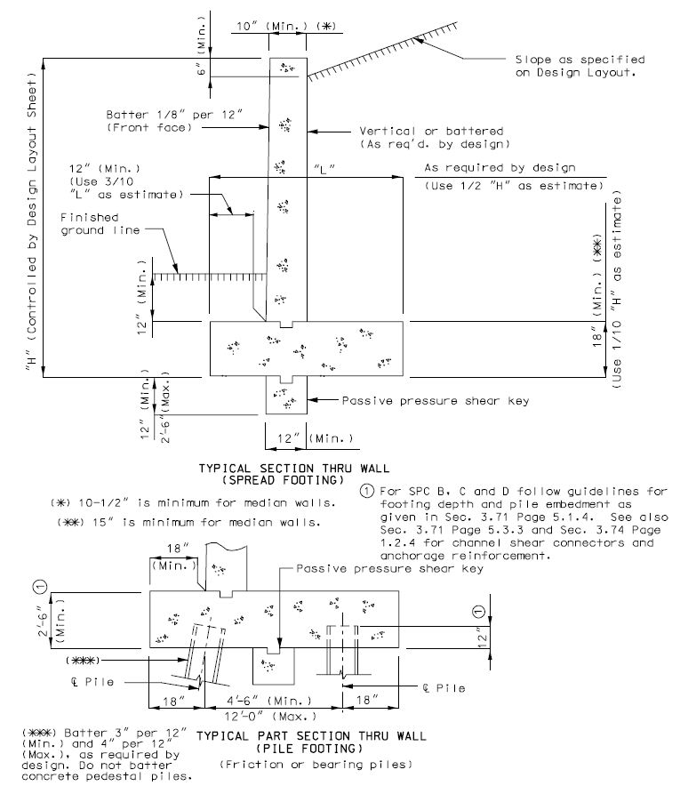
Each section of wall shall be in increments of 4 ft. with a maximum length of 28'-0".
Cantilever Walls - L-Shaped
Each section of wall shall be in increments of 4 ft. with a maximum length of 28'-0".
Counterfort Walls
| Notes: |
| Dimension "A" |
| • Maximum length = 28'-0". |
| • Each section to be in 4'-0" increments. |
| • (See rustication recess details.) |
| Dimensions "B" & "C" |
| • As required by the design to balance the negative and positive moments. (See the design assumptions). |

| Notes: |
| Batter "D": |
| * As required to maintain 9" minimum at the top of the counterfort and 12" minimum edge distance at the top of the footing, between counterfort and footing edge. |
| * Batter to be given an eighth of an inch per foot of counterfort height. |
| Dimension "L": |
| * As required for stability. |
| * As an estimate, use "L" equal to 1/2 the height of "H". |
Sign-Board Type Counterfort Walls

| Notes: |
| Dimension "A" |
| * Maximum length = 28'-0". |
| * Each section to be in 4'-0" increments. |
| * (See rustication recess details.) |
| Dimensions "B" & "C" |
| * As required by the design to balance the negative and positive moments. (See the design assumptions). |
| Dimension "E" |
| * (Sign-board type only) |
| * As required to maintain footing pressure within the allowable for existing foundation material. 12" minimum. |

| Notes: |
| Batter "D": |
| * As required to maintain 9" minimum at the top of the counterfort and 12" minimum edge distance at the top of the footing, between counterfort and footing edge. |
| * Batter to be given an eighth of an inch per foot of counterfort height. |
| Dimension "L": |
| * As required for stability. |
| * As an estimate, use "L" equal to 1/2 the height of "H". |
751.40.8.15.9 Reinforcement
Cantilever Walls
| (*) Alternate long and short bars at equal spaces. |
| (**) If collision forces are assumed, use #4 @ 12" cts. min. and extend at least development length into footing. (See EPG 751.5.9.2.8.1 Development and Lap Splice General.) |
| (***) Theo. cut-off for bending + development length. (Wall height over 10' only.) |
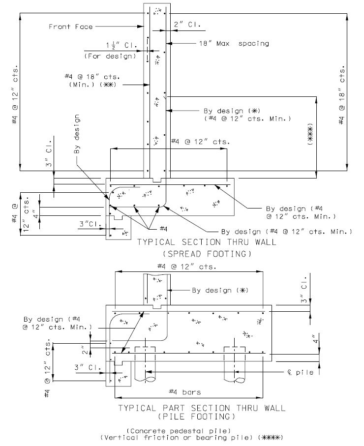
| (****) Due to site constriction. |
Cantilever Walls - L-Shaped
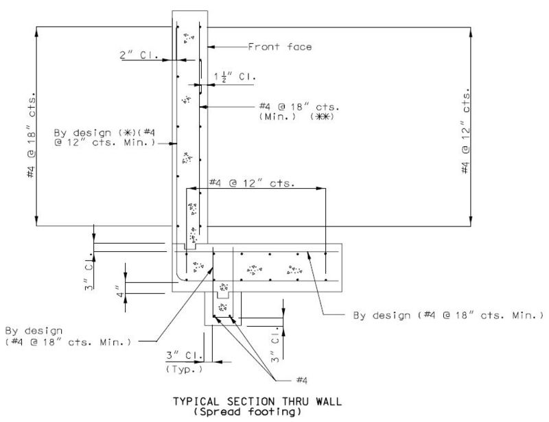
| (*) Do not splice stress bars in the fill face at top of footing. |
| (**) If collision forces are assumed, use #4 @ 12" cts. min. and extend at least development length into footing. (See EPG 751.5.9.2.8.1 Development and Lap Splice General.) |
Counterfort Walls
- Wall and Stem
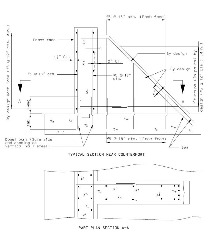
| (*) Use development length or standard hook in accordance with EPG 751.5.9.2.8.1 Development and Lap Splice General. |
| (**) See lap splices Class B. (See EPG 751.5.9.2.8.1 Development and Lap Splice General.) |
- Footing
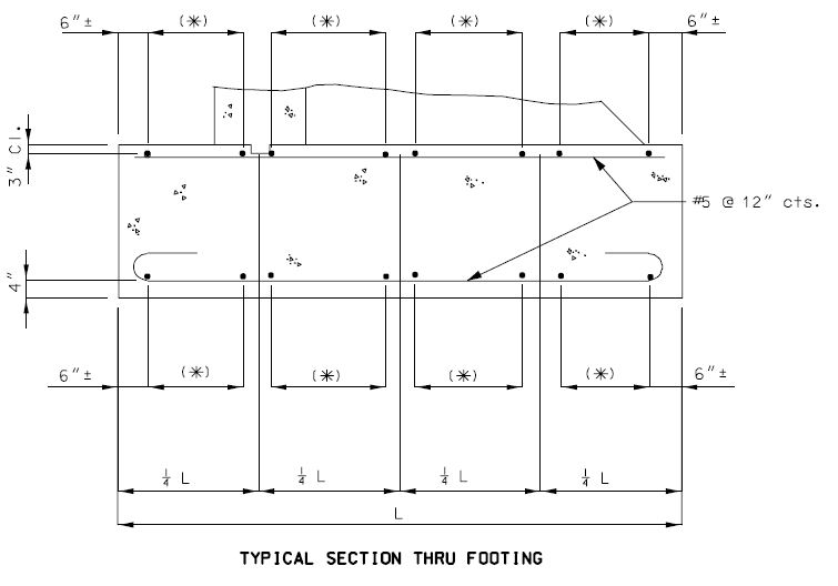
| (*) By design for loads and footing pressures on section under consideration. (#5 @ 12" cts. is the minimum.) |
Counterfort Walls - Sign-Board Type
- Wall and Stem
- Refer to "Counterfort Walls, Wall and Stem", above.
- Spread Footing
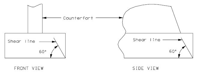
- If the shear line is within the counterfort projected (longitudinally or transversely), the footing may be considered satisfactory for all conditions. If outside of the counterfort projected, the footing must be analyzed and reinforced for bending and checked for bond stress and for diagonal tension stress.
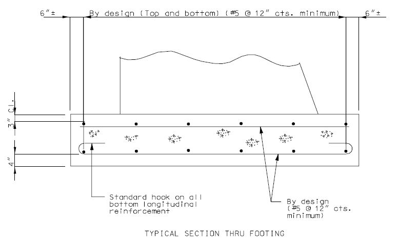
751.40.8.15.10 Details
Non-Keyed Joints
Each section of wall shall be in increments of 4 ft. with a maximum length of 28'-0".
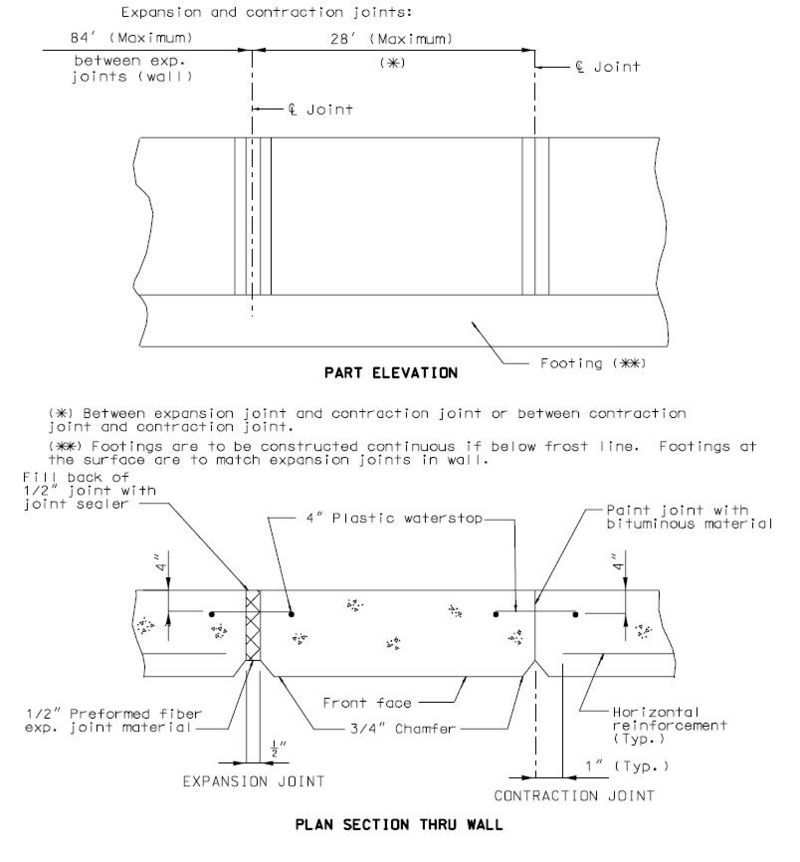
Keyed Joints
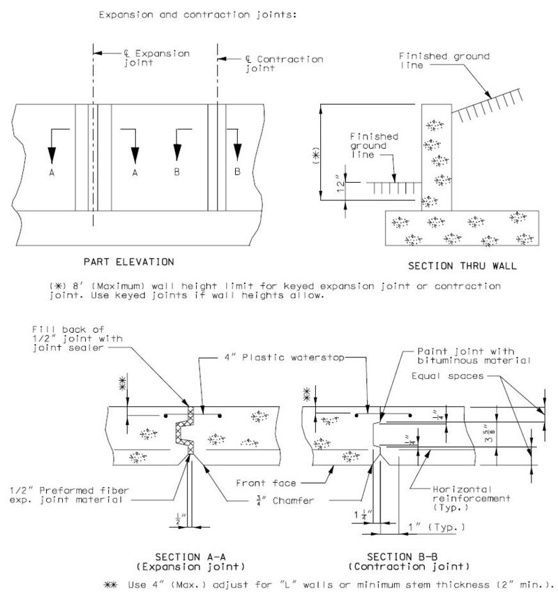
Rustication Recess
Drains
Construction Joint Keys:
- Cantilever Walls
- Counterfort Walls

- Key length: Divide the length "A" into an odd number of spaces of equal lengths. Each space shall not exceed a length of 24 inches. Use as few spaces as possible with the minimum number of spaces equal to three (or one key).
- Key width = Counterfort width/3 (to the nearest inch)
- Key depth = 2" (nominal)
- Sign-Board Walls
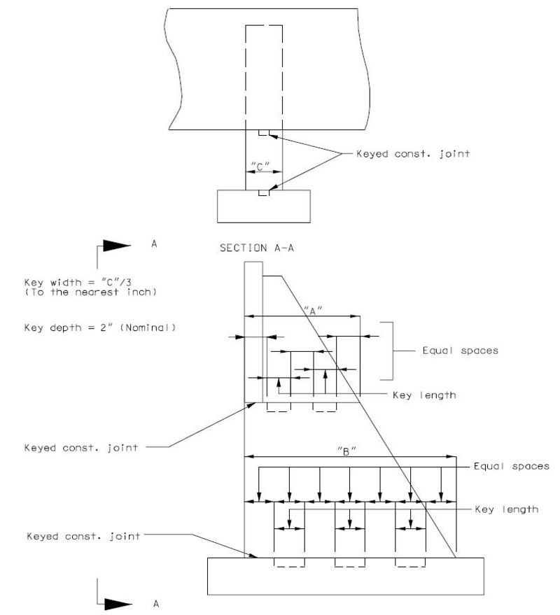
- Key length = divide length "A" or "B" into an odd number of spaces of equal lengths. Each space length shall not exceed 24 inches. Use as few spaces as possible with the minimum number of spaces equal to three (or one key).
