237.2 Title Sheet: Difference between revisions
m reformat paragraph |
mNo edit summary |
||
| (10 intermediate revisions by 2 users not shown) | |||
| Line 2: | Line 2: | ||
The title sheet identifies the set of plans, conveys the general type of improvement planned, and locates the improvement. Title sheet blanks are available on [[:Category:125 CADD Services|CADD]] for district use. The title sheet includes, at least, the | The title sheet identifies the set of plans, conveys the general type of improvement planned, and locates the improvement. Title sheet blanks are available on [[:Category:125 CADD Services|CADD]] for district use. The first title sheet includes, at least, the information presented in EPG 237.2.1 through EPG 237.2.9. If additional title sheets are needed, only the title block information needs to be repeated. A note will be place in the lower right hand corner of the sheet stating "Title Sheet 1 of 2". | ||
===237.2.1 Design Designation=== | ===237.2.1 Design Designation=== | ||
The major criteria under which the improvement is designed are included on the title sheet. These criteria are determined in the appropriate | The major criteria under which the improvement is designed are included on the title sheet. These criteria are determined in the appropriate [[:Category:128 Conceptual Studies|conceptual study report]], in the [[:Category:126 Location Study and Alternatives Analysis|location study/environmental report]], or during design of the project. The design designation consists of: | ||
:(1) functional classification, | :(1) [http://www.modot.org/newsandinfo/functionalclassificationmaps/index.htm functional classification], | ||
:(2) present daily traffic volume, AADT, | :(2) present [http://modot.org/safety/documents/2013_Traffic_Statewide.pdf daily traffic volume], AADT, | ||
:(3) a projected traffic volume, AADT, | :(3) a projected traffic volume, AADT, | ||
:(4) design hourly volume percentage, DHV, | :(4) design hourly volume percentage, DHV, | ||
| Line 20: | Line 20: | ||
===237.2.2 Right of Way Access Note=== | ===237.2.2 Right of Way Access Note=== | ||
A note referring to the type of access control is required on all projects where right of way acquisition is involved. Four types of right of way access notes are available: (1) normal right of way, (2) controlled access, (3) fully controlled access and (4) partial controlled access. The three controlled access notes are available on CADD. If right of way is not required, a note to that effect is shown. | A note referring to the type of access control is required on all projects where right of way acquisition is involved. Four types of right of way access notes are available: | ||
:(1) normal right of way, | |||
:(2) controlled access, | |||
:(3) fully controlled access and | |||
:(4) partial controlled access. | |||
The three controlled access notes are available on CADD. If right of way is not required, a note to that effect is shown. | |||
===237.2.3 Conventional Symbols=== | ===237.2.3 Conventional Symbols=== | ||
| Line 28: | Line 35: | ||
===237.2.4 Location Sketch=== | ===237.2.4 Location Sketch=== | ||
The sketch showing the location and limits of the improvement is added to the title sheet by the district. The location sketch shows physical features that will aid in the identification of the proposed road location, including intersecting and adjacent roads, prominent landmarks, towns, section lines, section numbers, and a north arrow. The delineation of the proposed roadway is to be adequate to allow visual identification of its features, such as whether it’s dual or single lane, location of [[Outer Roads and Service Roads|outer roadways]], bridges, interchanges, ramps, etc. The major items of work are noted. The project’s beginning and ending points are identified by station and log mile, along with any stationing equations, exceptions, or reverse points. The USGS 7.5 minute series topographic maps may be used as a base from which to develop the location sketch. A graphic scale is included for the location sketch so the scale will be applicable on reduced size prints. | The sketch showing the location and limits of the improvement is added to the title sheet by the district. The location sketch shows physical features that will aid in the identification of the proposed road location, including intersecting and adjacent roads, prominent landmarks, towns, section lines, section numbers, and a north arrow. The delineation of the proposed roadway is to be adequate to allow visual identification of its features, such as whether it’s dual or single lane, location of [[232.5 Freeways#Outer Roads and Service Roads|outer roadways]], bridges, interchanges, ramps, etc. The major items of work are noted. The project’s beginning and ending points are identified by station and log mile, along with any stationing equations, exceptions, or reverse points. The USGS 7.5 minute series topographic maps may be used as a base from which to develop the location sketch. A graphic scale is included for the location sketch so the scale will be applicable on reduced size prints. | ||
===237.2.5 Title Block=== | ===237.2.5 Title Block=== | ||
The title block is filled out by the district, with the exception of the project number. Design | The title block is filled out by the district, with the exception of the contract ID and project number. Central Office Design will provide these numbers when necessary. The information in the title block will be same on all the sheets in the job number. | ||
===237.2.6 Index of Sheets=== | ===237.2.6 Index of Sheets=== | ||
A complete index of the sheets in the plans is shown on the title sheet. | A complete index of the sheets in the plans is shown on the title sheet and should be included on the first title page. District Design adds the number of sheets for bridge plans. | ||
===237.2.7 Length of Project=== | ===237.2.7 Length of Project=== | ||
The length of project is the total length of the improvement less equations and exceptions as noted in the plans. Examples of common exceptions are existing surfaces to be left in place, existing bridges to be used in place, existing intersections, and railroad grade crossings where the exception is the distance between the ends of railroad crossties. | The length of project is the total length of the improvement less equations and exceptions as noted in the plans. Examples of common exceptions are existing surfaces to be left in place, existing bridges to be used in place, existing intersections, and railroad grade crossings where the exception is the distance between the ends of railroad crossties. | ||
[[image:237.2.8 2020.jpg|right|375px]] | |||
===237.2.8 Estimated Area of Disturbance=== | |||
The estimated area of disturbance is shown on the title sheet as a reference for bidders to determine if additional land disturbance permits are necessary for off-site borrow areas, waste disposal areas, staging areas etc. based on the common plan concept with MoDOT's permitted site. | |||
===237.2.9 Utility Information Note=== | |||
The following note is normally placed on the title sheet to inform contractors of the suitability of the utility information contained on the plans. | |||
:''"The existence and approximate location of utility facilities known to exist, as shown on the plans, are based on the best information available to the Commission at this time. This information is provided by the Commission "as-is" and the Commission expressly disclaims any representation or warranty as to the completeness, accuracy, or suitability of the information for any use. Reliance upon this information is done at the risk and peril of the user, and the Commission shall not be liable for any damages that may arise from any error in the information. It is, therefore, the responsibility of the contractor to verify the existence, location and status of any facility. Such verification includes direct contact with the listed utilities"''. | |||
The Utility Information Note may be placed on one of the plan and profile sheets. | |||
[[image:237.2.10.jpg|right|175px]] | |||
===237.2.10 Key Map=== | |||
Some districts show the location of the county where the work will be performed. This is an option and not required on the title sheet. | |||
[[category:237 Contract Plans|237.02]] | [[category:237 Contract Plans|237.02]] | ||
Latest revision as of 07:52, 30 April 2021

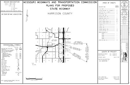
The title sheet identifies the set of plans, conveys the general type of improvement planned, and locates the improvement. Title sheet blanks are available on CADD for district use. The first title sheet includes, at least, the information presented in EPG 237.2.1 through EPG 237.2.9. If additional title sheets are needed, only the title block information needs to be repeated. A note will be place in the lower right hand corner of the sheet stating "Title Sheet 1 of 2".
237.2.1 Design Designation
The major criteria under which the improvement is designed are included on the title sheet. These criteria are determined in the appropriate conceptual study report, in the location study/environmental report, or during design of the project. The design designation consists of:
- (1) functional classification,
- (2) present daily traffic volume, AADT,
- (3) a projected traffic volume, AADT,
- (4) design hourly volume percentage, DHV,
- (5) directional distribution of traffic percentage, D,
- (6) percentage of trucks, T, and
- (7) anticipated posted speed, V.
The design hourly traffic volume, directional distribution of traffic, and percentage of trucks may not be required; however, all information available is to be included. The designer is to carefully consider the importance of this information being archived with the plans before arbitrarily removing it from the title sheet.
237.2.2 Right of Way Access Note
A note referring to the type of access control is required on all projects where right of way acquisition is involved. Four types of right of way access notes are available:
- (1) normal right of way,
- (2) controlled access,
- (3) fully controlled access and
- (4) partial controlled access.
The three controlled access notes are available on CADD. If right of way is not required, a note to that effect is shown.
237.2.3 Conventional Symbols

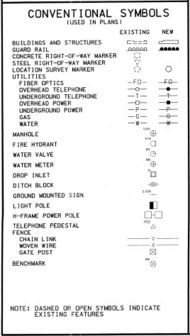
The blank as furnished to the district contains a basic list of conventional symbols. If additional symbols are used on the plans, the district adds all such symbols.
237.2.4 Location Sketch
The sketch showing the location and limits of the improvement is added to the title sheet by the district. The location sketch shows physical features that will aid in the identification of the proposed road location, including intersecting and adjacent roads, prominent landmarks, towns, section lines, section numbers, and a north arrow. The delineation of the proposed roadway is to be adequate to allow visual identification of its features, such as whether it’s dual or single lane, location of outer roadways, bridges, interchanges, ramps, etc. The major items of work are noted. The project’s beginning and ending points are identified by station and log mile, along with any stationing equations, exceptions, or reverse points. The USGS 7.5 minute series topographic maps may be used as a base from which to develop the location sketch. A graphic scale is included for the location sketch so the scale will be applicable on reduced size prints.
237.2.5 Title Block
The title block is filled out by the district, with the exception of the contract ID and project number. Central Office Design will provide these numbers when necessary. The information in the title block will be same on all the sheets in the job number.
237.2.6 Index of Sheets
A complete index of the sheets in the plans is shown on the title sheet and should be included on the first title page. District Design adds the number of sheets for bridge plans.
237.2.7 Length of Project
The length of project is the total length of the improvement less equations and exceptions as noted in the plans. Examples of common exceptions are existing surfaces to be left in place, existing bridges to be used in place, existing intersections, and railroad grade crossings where the exception is the distance between the ends of railroad crossties.

237.2.8 Estimated Area of Disturbance
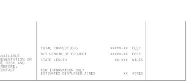
The estimated area of disturbance is shown on the title sheet as a reference for bidders to determine if additional land disturbance permits are necessary for off-site borrow areas, waste disposal areas, staging areas etc. based on the common plan concept with MoDOT's permitted site.
237.2.9 Utility Information Note
The following note is normally placed on the title sheet to inform contractors of the suitability of the utility information contained on the plans.
- "The existence and approximate location of utility facilities known to exist, as shown on the plans, are based on the best information available to the Commission at this time. This information is provided by the Commission "as-is" and the Commission expressly disclaims any representation or warranty as to the completeness, accuracy, or suitability of the information for any use. Reliance upon this information is done at the risk and peril of the user, and the Commission shall not be liable for any damages that may arise from any error in the information. It is, therefore, the responsibility of the contractor to verify the existence, location and status of any facility. Such verification includes direct contact with the listed utilities".
The Utility Information Note may be placed on one of the plan and profile sheets.

237.2.10 Key Map
Some districts show the location of the county where the work will be performed. This is an option and not required on the title sheet.